
Hardware Installation Guide
Page 3
... i-ix Product Overview 1-1 Setting Up the Switch 1-1 Features 1-1 Front Panel Description 1-3 Fast Ethernet Switch Front Panel Descriptions 1-3 Gigabit Ethernet Switch Front Panel Descriptions 1-6 10/100 and 10/100/1000 Ports 1-8 PoE Ports 1-9 SFP Module Slots 1-10 SFP Modules 1-10 SFP Module Patch Cable 1-10 Dual-Purpose Port ...1-15 Cable Guard 1-15 Rear Panel Description 1-15 Internal Power Supply 1-18 DC Power Connector 1-18 Cisco RPS 1-19 Cisco RPS 2300 1-19 Cisco RPS 675 1-19 Console Port 1-19 Security Slots 1-20 Management Options 1-20 Catalyst 3560 Switch Hardware Installation Guide iii
... i-ix Product Overview 1-1 Setting Up the Switch 1-1 Features 1-1 Front Panel Description 1-3 Fast Ethernet Switch Front Panel Descriptions 1-3 Gigabit Ethernet Switch Front Panel Descriptions 1-6 10/100 and 10/100/1000 Ports 1-8 PoE Ports 1-9 SFP Module Slots 1-10 SFP Modules 1-10 SFP Module Patch Cable 1-10 Dual-Purpose Port ...1-15 Cable Guard 1-15 Rear Panel Description 1-15 Internal Power Supply 1-18 DC Power Connector 1-18 Cisco RPS 1-19 Cisco RPS 2300 1-19 Cisco RPS 675 1-19 Console Port 1-19 Security Slots 1-20 Management Options 1-20 Catalyst 3560 Switch Hardware Installation Guide iii

Hardware Installation Guide
Page 4
... Wall Mounting 2-12 Attaching the RPS Connector Cover 2-13 Mounting the Switch on a Wall 2-14 Table- Mounting 2-15 Installing and Removing SFP Modules 2-15 Installing SFP Modules into SFP Module Slots 2-16 Removing SFP Modules from the Switch 2-8 Attaching Brackets to the Catalyst 3560 Switch 2-8 Mounting the Switch in a Rack 2-10 Attaching the Cable Guide 2-11 Wall-Mounting 2-12...
... Wall Mounting 2-12 Attaching the RPS Connector Cover 2-13 Mounting the Switch on a Wall 2-14 Table- Mounting 2-15 Installing and Removing SFP Modules 2-15 Installing SFP Modules into SFP Module Slots 2-16 Removing SFP Modules from the Switch 2-8 Attaching Brackets to the Catalyst 3560 Switch 2-8 Mounting the Switch in a Rack 2-10 Attaching the Cable Guide 2-11 Wall-Mounting 2-12...

Hardware Installation Guide
Page 6
...E N D I X INDEX Technical Specifications A-1 Connector and Cable Specifications B-1 Connector Specifications B-1 10/100 and 10/100/1000 Ports B-1 SFP Module Ports B-2 Dual-Purpose Ports B-3 Console Port B-3 Cable and Adapter Specifications B-4 SFP Module Cable Specifications B-4 Two Twisted-Pair Cable Pinouts B-5 Four Twisted-Pair Cable Pinouts for 1000BASE-T Ports B-6 Identifying a Crossover Cable B-6 Adapter...Switch C-2 Wiring the DC-Input Power Source C-5 Configuring the Switch with the CLI-Based Setup Program D-1 Preparing for Setup D-1 Completing the Setup Program D-3 Catalyst 3560 Switch...
...E N D I X INDEX Technical Specifications A-1 Connector and Cable Specifications B-1 Connector Specifications B-1 10/100 and 10/100/1000 Ports B-1 SFP Module Ports B-2 Dual-Purpose Ports B-3 Console Port B-3 Cable and Adapter Specifications B-4 SFP Module Cable Specifications B-4 Two Twisted-Pair Cable Pinouts B-5 Four Twisted-Pair Cable Pinouts for 1000BASE-T Ports B-6 Identifying a Crossover Cable B-6 Adapter...Switch C-2 Wiring the DC-Input Power Source C-5 Configuring the Switch with the CLI-Based Setup Program D-1 Preparing for Setup D-1 Completing the Setup Program D-3 Catalyst 3560 Switch...
Hardware Installation Guide
Page 8
... cause bodily injury. You are available from this Cisco.com site: http://www.cisco.com/en/US/products/hw/modules/ps5455/products_device_support_tables_list.html • Cisco Gigabit Ethernet Transceiver Modules Compatibility Matrix • Cisco 100-Megabit Ethernet SFP Modules Compatibility Matrix • Cisco CWDM SFP Transceiver Compatibility Matrix Catalyst 3560 Switch Hardware Installation Guide viii OL-6337-07 Use the...
... cause bodily injury. You are available from this Cisco.com site: http://www.cisco.com/en/US/products/hw/modules/ps5455/products_device_support_tables_list.html • Cisco Gigabit Ethernet Transceiver Modules Compatibility Matrix • Cisco 100-Megabit Ethernet SFP Modules Compatibility Matrix • Cisco CWDM SFP Transceiver Compatibility Matrix Catalyst 3560 Switch Hardware Installation Guide viii OL-6337-07 Use the...

Hardware Installation Guide
Page 12
...-8PC and the Catalyst 3560-12PC-S switches are smaller than the other Catalyst 3560 switches. Supported SFP modules: • 100BASE-BX10 (only Catalyst 3560 8- and 12-port switches) • 100BASE-FX • 100BASE-LX (only Catalyst 3560 8- and 48-port switches) • 1000BASE-ZX • Coarse Wavelength-Division Multiplexing (CWDM) • SFP module patch cable. (CAB-SFP-50CM=.) Switches running Cisco IOS Release...
...-8PC and the Catalyst 3560-12PC-S switches are smaller than the other Catalyst 3560 switches. Supported SFP modules: • 100BASE-BX10 (only Catalyst 3560 8- and 12-port switches) • 100BASE-FX • 100BASE-LX (only Catalyst 3560 8- and 48-port switches) • 1000BASE-ZX • Coarse Wavelength-Division Multiplexing (CWDM) • SFP module patch cable. (CAB-SFP-50CM=.) Switches running Cisco IOS Release...

Hardware Installation Guide
Page 13
.../1000 Ports, page 1-8 • PoE Ports, page 1-9 • SFP Module Slots, page 1-10 • Dual-Purpose Port, page 1-10 • LEDs, page 1-11 • Cable Guard, page 1-15 Fast Ethernet Switch Front Panel Descriptions • Catalyst 3560-24PS and 3560V2-24PS Switch Front Panel, Figure 1-1 on page 1-3 • Catalyst 3560-24TS-S, 3560V2-24TS, and 3560V2-24TS-SD...
.../1000 Ports, page 1-8 • PoE Ports, page 1-9 • SFP Module Slots, page 1-10 • Dual-Purpose Port, page 1-10 • LEDs, page 1-11 • Cable Guard, page 1-15 Fast Ethernet Switch Front Panel Descriptions • Catalyst 3560-24PS and 3560V2-24PS Switch Front Panel, Figure 1-1 on page 1-3 • Catalyst 3560-24TS-S, 3560V2-24TS, and 3560V2-24TS-SD...

Hardware Installation Guide
Page 14
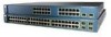
... 19 20 21 22 23 24 23X Catalyst 3560 SERIES 14X 24X 1 2 1 2 1 10/100 ports 2 SFP module slots The 10/100 PoE ports on the switch are grouped in pairs. The SFP module slots are numbered 1 and 2. Figure 1-3 Catalyst 3560-48PS and 3560V2-48PS Switch Front Panel 97911 SYST RPS STAT DUPLX... 35 36 37 38 39 40 41 42 43 44 45 46 47 48 Catalyst 3560 SERIES PoE-48 47X 32X 34X 1 3 48X 2 4 1 2 1 10/100 PoE ports 2 SFP module slots Catalyst 3560 Switch Hardware Installation Guide 1-4 OL-6337-07 The SFP module slots are numbered 1 to 4. Port 3 is above port 4, and so on...
... 19 20 21 22 23 24 23X Catalyst 3560 SERIES 14X 24X 1 2 1 2 1 10/100 ports 2 SFP module slots The 10/100 PoE ports on the switch are grouped in pairs. The SFP module slots are numbered 1 and 2. Figure 1-3 Catalyst 3560-48PS and 3560V2-48PS Switch Front Panel 97911 SYST RPS STAT DUPLX... 35 36 37 38 39 40 41 42 43 44 45 46 47 48 Catalyst 3560 SERIES PoE-48 47X 32X 34X 1 3 48X 2 4 1 2 1 10/100 PoE ports 2 SFP module slots Catalyst 3560 Switch Hardware Installation Guide 1-4 OL-6337-07 The SFP module slots are numbered 1 to 4. Port 3 is above port 4, and so on...

Hardware Installation Guide
Page 15
... on. For more information on the dual-purpose port, see the "Console Port" section on page 1-10. The first member of the Catalyst 3560-8PC switch and the Catalyst 3560-12PC-S switch (Figure 1-5 and Figure 1-6). Figure 1-5 Catalyst 3560-8PC Switch Front Panel SYST STAT DPLX SPD MODE CONSOLE 1x 2x 3x 4x 5x 6x 7x 8x... 31 32 16X 18X 33 31X 33X 34 35 36 37 38 39 40 41 42 43 44 45 46 47 48 47X 32X 34X Catalyst 3560 SERIES 1 3 48X 2 4 1 2 1 10/100 ports 2 SFP module slots The console port, 10/100 PoE ports, and a dual-purpose port are grouped in Figure 1-4. The...
... on. For more information on the dual-purpose port, see the "Console Port" section on page 1-10. The first member of the Catalyst 3560-8PC switch and the Catalyst 3560-12PC-S switch (Figure 1-5 and Figure 1-6). Figure 1-5 Catalyst 3560-8PC Switch Front Panel SYST STAT DPLX SPD MODE CONSOLE 1x 2x 3x 4x 5x 6x 7x 8x... 31 32 16X 18X 33 31X 33X 34 35 36 37 38 39 40 41 42 43 44 45 46 47 48 47X 32X 34X Catalyst 3560 SERIES 1 3 48X 2 4 1 2 1 10/100 ports 2 SFP module slots The console port, 10/100 PoE ports, and a dual-purpose port are grouped in Figure 1-4. The...

Hardware Installation Guide
Page 16
...Catalyst 3560G-24PS Switch Front Panel 119676 SYST RPS STAT DUPLX SPEED PoE MODE 12 1X 34 56 78 9 10 11 12 11X 2X 12X 13 14 13X 15 16 17 18 19 20 21 22 23 24 Catalyst 3560G SERIES PoE-24 23X 25 14X 27 24X 26 28 1 2 1 10/100/1000 ports 2 SFP...-purpose port Gigabit Ethernet Switch Front Panel Descriptions • Catalyst 3560G-24PS Switch Front Panel, Figure 1-7 on page 1-6 • Catalyst 3560G-24TS Switch Front Panel, Figure 1-8 on page 1-7 • Catalyst 3560G-48PS Switch Front Panel, Figure 1-9 on page 1-7 • Catalyst 3560G-48TS Switch Front Panel, Figure ...
...Catalyst 3560G-24PS Switch Front Panel 119676 SYST RPS STAT DUPLX SPEED PoE MODE 12 1X 34 56 78 9 10 11 12 11X 2X 12X 13 14 13X 15 16 17 18 19 20 21 22 23 24 Catalyst 3560G SERIES PoE-24 23X 25 14X 27 24X 26 28 1 2 1 10/100/1000 ports 2 SFP...-purpose port Gigabit Ethernet Switch Front Panel Descriptions • Catalyst 3560G-24PS Switch Front Panel, Figure 1-7 on page 1-6 • Catalyst 3560G-24TS Switch Front Panel, Figure 1-8 on page 1-7 • Catalyst 3560G-48PS Switch Front Panel, Figure 1-9 on page 1-7 • Catalyst 3560G-48TS Switch Front Panel, Figure ...

Hardware Installation Guide
Page 17
... 35 36 37 38 39 40 41 42 43 44 45 46 47 48 Catalyst 3560G SERIES PoE-48 47X 32X 34X 49 51 48X 50 52 1 2 1 10/100/1000 ports 2 SFP module slots OL-6337-07 Catalyst 3560 Switch Hardware Installation Guide 1-7 Port 3 is above the second member (port 2) on the left ,... , as shown in Figure 1-9. Chapter 1 Product Overview Front Panel Description The 10/100/1000 ports on the Catalyst 3560-24TS switch are grouped in pairs. The SFP module slots are numbered 25 to 52. The SFP module slots are numbered 49 to 28. The first member of the pair (port 1) is above port 4,...
... 35 36 37 38 39 40 41 42 43 44 45 46 47 48 Catalyst 3560G SERIES PoE-48 47X 32X 34X 49 51 48X 50 52 1 2 1 10/100/1000 ports 2 SFP module slots OL-6337-07 Catalyst 3560 Switch Hardware Installation Guide 1-7 Port 3 is above the second member (port 2) on the left ,... , as shown in Figure 1-9. Chapter 1 Product Overview Front Panel Description The 10/100/1000 ports on the Catalyst 3560-24TS switch are grouped in pairs. The SFP module slots are numbered 25 to 52. The SFP module slots are numbered 49 to 28. The first member of the pair (port 1) is above port 4,...

Hardware Installation Guide
Page 18
Port 3 is above the second member (port 2) on the Catalyst 3560G-48TS switch are authorized within 328 feet (100 meters). The SFP module slots are made aware of security. Figure 1-10 Catalyst 3560G-48TS Switch Front Panel 119675 SYST RPS STAT DUPLX SPEED MODE 1 1X 2X 23 45...attached device must be accessed only through the use Category 3 or Category 4 cables. Catalyst 3560 Switch Hardware Installation Guide 1-8 OL-6337-07 If the connected device also supports autonegotiation, the switch port negotiates the best connection (the fastest line speed that present a shock hazard ...
Port 3 is above the second member (port 2) on the Catalyst 3560G-48TS switch are authorized within 328 feet (100 meters). The SFP module slots are made aware of security. Figure 1-10 Catalyst 3560G-48TS Switch Front Panel 119675 SYST RPS STAT DUPLX SPEED MODE 1 1X 2X 23 45...attached device must be accessed only through the use Category 3 or Category 4 cables. Catalyst 3560 Switch Hardware Installation Guide 1-8 OL-6337-07 If the connected device also supports autonegotiation, the switch port negotiates the best connection (the fastest line speed that present a shock hazard ...

Hardware Installation Guide
Page 19
... default on the other end of the Catalyst 3560-8PC, 3560-12PC-S, 3560-24PS, and 3560V2-24PS switch 10/100 ports or the Catalyst 3560G-24PS switch 10/100/1000 ports deliver up to the powered device. Pinouts for proper operation. For releases between Cisco IOS Release 12.1(14)EA1 and 12.2(...The Catalyst 3560-12PC-S switch delivers a maximum power output of device on switches running Cisco IOS Release 12.2(18)SE or later. The device manager, Network Assistant, and the CLI provide PoE settings for connections to a copper 10/100, 10/100/1000, or 1000BASE-T SFP module port on the switch, ...
... default on the other end of the Catalyst 3560-8PC, 3560-12PC-S, 3560-24PS, and 3560V2-24PS switch 10/100 ports or the Catalyst 3560G-24PS switch 10/100/1000 ports deliver up to the powered device. Pinouts for proper operation. For releases between Cisco IOS Release 12.1(14)EA1 and 12.2(...The Catalyst 3560-12PC-S switch delivers a maximum power output of device on switches running Cisco IOS Release 12.2(18)SE or later. The device manager, Network Assistant, and the CLI provide PoE settings for connections to a copper 10/100, 10/100/1000, or 1000BASE-T SFP module port on the switch, ...

Hardware Installation Guide
Page 20
... Description Chapter 1 Product Overview Many legacy powered devices, including older Cisco IP phones and access points that first links up. SFP Module Patch Cable The switch supports the SFP module patch cable (CAB-SFP-50CM=), a 0.5 meter, copper, passive cable with RJ-45 connectors...the SFP module connector. However, you must use the media-type interface configuration command to a copper SFP module. Use a Category 5 cable with SFP module connectors at a time. SFP Modules The switch uses Gigabit Ethernet SFP modules to other Catalyst series switches, you can use the SFP ...
... Description Chapter 1 Product Overview Many legacy powered devices, including older Cisco IP phones and access points that first links up. SFP Module Patch Cable The switch supports the SFP module patch cable (CAB-SFP-50CM=), a 0.5 meter, copper, passive cable with RJ-45 connectors...the SFP module connector. However, you must use the media-type interface configuration command to a copper SFP module. Use a Category 5 cable with SFP module connectors at a time. SFP Modules The switch uses Gigabit Ethernet SFP modules to other Catalyst series switches, you can use the SFP ...

Hardware Installation Guide
Page 23
...modes. PoE mode is shown on the port LEDs. The port operating speed: 10, 100, or 10001 Mb/s. Table 1-6 explains how to Catalyst 3560 switches that support PoE. PoE PoE port power The PoE status. 1. The PoE LED applies only to interpret the port LED colors in a fault ...condition. OL-6337-07 Catalyst 3560 Switch Hardware Installation Guide 1-13 This is not selected. When installed in Catalyst 3560 switches, 1000BASE-T SFP modules can operate at 10, 100, or 1000 Mb/s in full-duplex mode or at least one...
...modes. PoE mode is shown on the port LEDs. The port operating speed: 10, 100, or 10001 Mb/s. Table 1-6 explains how to Catalyst 3560 switches that support PoE. PoE PoE port power The PoE status. 1. The PoE LED applies only to interpret the port LED colors in a fault ...condition. OL-6337-07 Catalyst 3560 Switch Hardware Installation Guide 1-13 This is not selected. When installed in Catalyst 3560 switches, 1000BASE-T SFP modules can operate at 10, 100, or 1000 Mb/s in full-duplex mode or at least one...

Hardware Installation Guide
Page 24
... checks the network topology for the port has been disabled. Green Port is sending or receiving data. Note When installed in Catalyst 3560 switches, 1000BASE-T SFP modules can remain amber for up to 30 seconds as excessive collisions, cyclic redundancy check (CRC) errors, and alignment and ... port was administratively shut down. Error frames can be used to connect Cisco prestandard IP Phones or wireless access points or IEEE 802.3af-compliant devices to the powered device will exceed the 370 W switch power capacity. STAT (port status) DUPLX (duplex) SPEED Caution PoE ...
... checks the network topology for the port has been disabled. Green Port is sending or receiving data. Note When installed in Catalyst 3560 switches, 1000BASE-T SFP modules can remain amber for up to 30 seconds as excessive collisions, cyclic redundancy check (CRC) errors, and alignment and ... port was administratively shut down. Error frames can be used to connect Cisco prestandard IP Phones or wireless access points or IEEE 802.3af-compliant devices to the powered device will exceed the 370 W switch power capacity. STAT (port status) DUPLX (duplex) SPEED Caution PoE ...
Hardware Installation Guide
Page 25
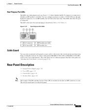
... • Internal Power Supply, page 1-18 • Cisco RPS, page 1-19 • Console Port, page 1-19 • Security Slots, page 1-20 Note The Catalyst 3560-8PC and the Catalyst 3560-12PC-S switches do not have the same meaning as an SFP module, but not both at the same time. Chapter ...1 Product Overview Rear Panel Description Dual-Purpose Port LEDs The LEDs on the front panel. You can order an optional cable guard to secure cables to Table 1-6. To order a cable guard (CBLGRD-C3560-12PC or CBLGRD-C3560-8PC), contact your Cisco...
... • Internal Power Supply, page 1-18 • Cisco RPS, page 1-19 • Console Port, page 1-19 • Security Slots, page 1-20 Note The Catalyst 3560-8PC and the Catalyst 3560-12PC-S switches do not have the same meaning as an SFP module, but not both at the same time. Chapter ...1 Product Overview Rear Panel Description Dual-Purpose Port LEDs The LEDs on the front panel. You can order an optional cable guard to secure cables to Table 1-6. To order a cable guard (CBLGRD-C3560-12PC or CBLGRD-C3560-8PC), contact your Cisco...
Hardware Installation Guide
Page 33
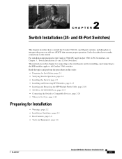
...19 • Connecting the Switch to Compatible Devices, page 2-20 • Where to Go Next, page 2-24 Preparing for installing, and connecting to the SFP modules apply to all Catalyst 3560 switches. It also describes how ...to make connections to interpret the power-on self-test (POST) that ensures proper operation. For installation information for the Catalyst 3560-8PC and Catalyst 3560 12-PC-S switches, see Chapter 3, "Switch Installation (8- and 48-port switches, including how to the switch. and 12-Port Switches...
...19 • Connecting the Switch to Compatible Devices, page 2-20 • Where to Go Next, page 2-24 Preparing for installing, and connecting to the SFP modules apply to all Catalyst 3560 switches. It also describes how ...to make connections to interpret the power-on self-test (POST) that ensures proper operation. For installation information for the Catalyst 3560-8PC and Catalyst 3560 12-PC-S switches, see Chapter 3, "Switch Installation (8- and 48-port switches, including how to the switch. and 12-Port Switches...

Hardware Installation Guide
Page 37
...10/100/1000 ports, and 1000BASE-T SFP module ports, cable lengths from sources of the switch should be sure to observe these conditions: - and 48-Port Switches) Statement 371-Power Cable and AC Adapter Preparing for the Catalyst 3560 switch. Note The grounding architecture of single-mode...Appendix A, "Technical Specifications." • Airflow around the unit does not exceed 113°F (45°C). Chapter 2 Switch Installation (24- Catalyst 3560 switch SFP ports use shorter lengths of this product is safely away from other devices that exit from either the left side or ...
...10/100/1000 ports, and 1000BASE-T SFP module ports, cable lengths from sources of the switch should be sure to observe these conditions: - and 48-Port Switches) Statement 371-Power Cable and AC Adapter Preparing for the Catalyst 3560 switch. Note The grounding architecture of single-mode...Appendix A, "Technical Specifications." • Airflow around the unit does not exceed 113°F (45°C). Chapter 2 Switch Installation (24- Catalyst 3560 switch SFP ports use shorter lengths of this product is safely away from other devices that exit from either the left side or ...

Hardware Installation Guide
Page 38
... connect the RPS to the AC power connector on the switch, connect one SFP module slot) Box Contents The switch getting started guide on the 1000BASE-ZX SFP module at each end of the link. • Cisco Ethernet Switches are equipped with cooling mechanisms, such as metal flakes from... construction activities). However, these fans and blowers can draw dust and other end of suspended particulate matter: - Catalyst 3560-8PC switch-8 10/100 ...
... connect the RPS to the AC power connector on the switch, connect one SFP module slot) Box Contents The switch getting started guide on the 1000BASE-ZX SFP module at each end of the link. • Cisco Ethernet Switches are equipped with cooling mechanisms, such as metal flakes from... construction activities). However, these fans and blowers can draw dust and other end of suspended particulate matter: - Catalyst 3560-8PC switch-8 10/100 ...
Hardware Installation Guide
Page 47
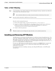
... are inserted into the SFP module slots on the bottom of the switch near an AC power source. Mounting Step 1 Locate the adhesive strip with the CLI-Based Setup Program." 3. After the switch is encoded with security information, which Cisco uses to the bottom of the switch. OL-6337-07 Catalyst 3560 Switch Hardware Installation Guide 2-15...
... are inserted into the SFP module slots on the bottom of the switch near an AC power source. Mounting Step 1 Locate the adhesive strip with the CLI-Based Setup Program." 3. After the switch is encoded with security information, which Cisco uses to the bottom of the switch. OL-6337-07 Catalyst 3560 Switch Hardware Installation Guide 2-15...

