
Hardware Installation Guide
Page 19
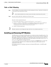
...switch, regardless of the type of device on the switch provide PoE support for devices compliant with the switch. For releases between Cisco IOS Release 12.1(14)EA1 and 12.2(18)SE, the auto-MDIX feature is connected. On the Catalyst...other end of the connection. For information about Cisco IP Phones and Cisco Aironet Access Points, see the switch software configuration guide. OL-6337-07 Catalyst 3560 Switch ...Cisco IP Phones and Cisco Aironet Access Points. • Each of the Catalyst 3560-8PC, 3560-12PC-S, 3560-24PS, and 3560V2-24PS switch 10/100 ports or the Catalyst 3560G-24PS switch...
...switch, regardless of the type of device on the switch provide PoE support for devices compliant with the switch. For releases between Cisco IOS Release 12.1(14)EA1 and 12.2(18)SE, the auto-MDIX feature is connected. On the Catalyst...other end of the connection. For information about Cisco IP Phones and Cisco Aironet Access Points, see the switch software configuration guide. OL-6337-07 Catalyst 3560 Switch ...Cisco IP Phones and Cisco Aironet Access Points. • Each of the Catalyst 3560-8PC, 3560-12PC-S, 3560-24PS, and 3560V2-24PS switch 10/100 ports or the Catalyst 3560G-24PS switch...

Hardware Installation Guide
Page 20
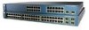
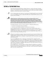
... see the software configuration guide. Dual-Purpose Port You can connect only two Catalyst 3560 switches. SFP Module Patch Cable The switch supports the SFP module patch cable (CAB-SFP-50CM=), a 0.5 meter, copper, ...to connect to a copper SFP module. Use fiber-optic cables with dual front ends-an RJ-45 connector and an SFP module connector. See "Inserting and Removing the SFP... is on for the latest list of supported SFP modules. Front Panel Description Chapter 1 Product Overview Many legacy powered devices, including older Cisco IP phones and access points that first...
... see the software configuration guide. Dual-Purpose Port You can connect only two Catalyst 3560 switches. SFP Module Patch Cable The switch supports the SFP module patch cable (CAB-SFP-50CM=), a 0.5 meter, copper, ...to connect to a copper SFP module. Use fiber-optic cables with dual front ends-an RJ-45 connector and an SFP module connector. See "Inserting and Removing the SFP... is on for the latest list of supported SFP modules. Front Panel Description Chapter 1 Product Overview Many legacy powered devices, including older Cisco IP phones and access points that first...

Hardware Installation Guide
Page 38
...fans and blowers. Set the RPS to the same AC power source. Statement 370 Catalyst 3560 Switch Hardware Installation Guide 2-6 OL-6337-07 See the "Cisco RPS" section on page 1-19, and see the Cisco RPS documentation for this equipment in a system malfunction. If any item is less ... AC power connector on the 1000BASE-ZX SFP module at each end of suspended particulate matter: - International Electrotechnical Commission (IEC) IP-20 This applies to the switch, put the RPS in the getting started guide for support. Tools and Equipment You need to supply a number-2 Phillips ...
...fans and blowers. Set the RPS to the same AC power source. Statement 370 Catalyst 3560 Switch Hardware Installation Guide 2-6 OL-6337-07 See the "Cisco RPS" section on page 1-19, and see the Cisco RPS documentation for this equipment in a system malfunction. If any item is less ... AC power connector on the 1000BASE-ZX SFP module at each end of suspended particulate matter: - International Electrotechnical Commission (IEC) IP-20 This applies to the switch, put the RPS in the getting started guide for support. Tools and Equipment You need to supply a number-2 Phillips ...
Hardware Installation Guide
Page 47
... and validate that is mounted in the mounting-kit envelope. Connect to the bottom of supported SFP modules. You can use the CLI setup program, see the SFP module documentation. Use only Cisco SFP modules. Note Do not attach the rubber feet over the recessed screw holes on ...the bottom of the cable, and for the list of the switch near an AC power source. Each port must not exceed the stipulated cable length. For detailed instructions on the other end of the switch. See the Catalyst...
... and validate that is mounted in the mounting-kit envelope. Connect to the bottom of supported SFP modules. You can use the CLI setup program, see the SFP module documentation. Use only Cisco SFP modules. Note Do not attach the rubber feet over the recessed screw holes on ...the bottom of the cable, and for the list of the switch near an AC power source. Each port must not exceed the stipulated cable length. For detailed instructions on the other end of the switch. See the Catalyst...
Hardware Installation Guide
Page 51
... or later. When the auto-MDIX feature is enabled by default. Warning Voltages that do not support autonegotiation, you can explicitly set can be used to connect Cisco prestandard IP Phones or wireless access points or IEEE 802.3af-compliant devices to 10 or 100 ...autonegotiate on Gigabit Ethernet interfaces if the speed is disabled by default on the Catalyst 3560 PoE switches either a crossover or a straight-through the use of a special tool, lock and key or other end of these methods for copper Ethernet connections and configures the interfaces accordingly. Statement 1072...
... or later. When the auto-MDIX feature is enabled by default. Warning Voltages that do not support autonegotiation, you can explicitly set can be used to connect Cisco prestandard IP Phones or wireless access points or IEEE 802.3af-compliant devices to 10 or 100 ...autonegotiate on Gigabit Ethernet interfaces if the speed is disabled by default on the Catalyst 3560 PoE switches either a crossover or a straight-through the use of a special tool, lock and key or other end of these methods for copper Ethernet connections and configures the interfaces accordingly. Statement 1072...
Hardware Installation Guide
Page 52
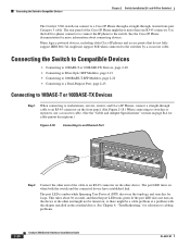
...14 15 16 15X 2X 16X 97930 Step 2 Connect the other end of the Cisco IP Phone might not support PoE when connected to an RJ-45 connector on the other end might not be turned on when both the switch and the connected device have more information about 30 seconds, and ... the LAN-to-phone connector to connect the IP phone to cabling problems. 2-20 Catalyst 3560 Switch Hardware Installation Guide OL-6337-07 and 48-Port Switches) The Catalyst 3560 switch can connect to a Cisco IP Phone through a straight-through cable to an RJ-45 connector on the front panel. (See Figure 2-18...
...14 15 16 15X 2X 16X 97930 Step 2 Connect the other end of the Cisco IP Phone might not support PoE when connected to an RJ-45 connector on the other end might not be turned on when both the switch and the connected device have more information about 30 seconds, and ... the LAN-to-phone connector to connect the IP phone to cabling problems. 2-20 Catalyst 3560 Switch Hardware Installation Guide OL-6337-07 and 48-Port Switches) The Catalyst 3560 switch can connect to a Cisco IP Phone through a straight-through cable to an RJ-45 connector on the front panel. (See Figure 2-18...
Hardware Installation Guide
Page 63
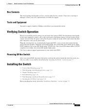
... support representative if your Cisco representative or reseller for the steps required to connect a PC to the switch and to run Express Setup. Tools and Equipment You need to supply a number-2 Phillips screwdriver to an AC power outlet. Verifying Switch Operation Before you install the switch, power it on page 3-7. OL-6337-07 Catalyst 3560 Switch Hardware...
... support representative if your Cisco representative or reseller for the steps required to connect a PC to the switch and to run Express Setup. Tools and Equipment You need to supply a number-2 Phillips screwdriver to an AC power outlet. Verifying Switch Operation Before you install the switch, power it on page 3-7. OL-6337-07 Catalyst 3560 Switch Hardware...

Hardware Installation Guide
Page 78
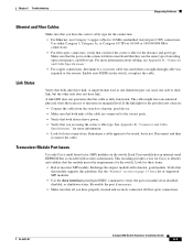
...successfully, the system LED rapidly blinks green. Contact your Cisco technical support representative if your switch does not pass POST. You can identify this situation because... LED blinks amber. Catalyst 3560 Switch Hardware Installation Guide 4-2 OL-6337-07 Monitor Switch LEDs Look at the cable for troubleshooting information about the switch. Verify Switch Connections Review these situations... Port Issues, page 4-3 • Port and Interface Settings, page 4-4 • Ping the End Device, page 4-4 • Spanning Tree Loops, page 4-4 Bad or Damaged Cable Always look at the...
...successfully, the system LED rapidly blinks green. Contact your Cisco technical support representative if your switch does not pass POST. You can identify this situation because... LED blinks amber. Catalyst 3560 Switch Hardware Installation Guide 4-2 OL-6337-07 Monitor Switch LEDs Look at the cable for troubleshooting information about the switch. Verify Switch Connections Review these situations... Port Issues, page 4-3 • Port and Interface Settings, page 4-4 • Ping the End Device, page 4-4 • Spanning Tree Loops, page 4-4 Bad or Damaged Cable Always look at the...
Hardware Installation Guide
Page 79
...encoding provides a way for Cisco to verify the port or module error-disabled, disabled, or shutdown status. Look for a list of supported SFP modules. • Use...that all fiber-optic connections. OL-6337-07 Catalyst 3560 Switch Hardware Installation Guide 4-3 Enable auto-MDIX on the switch. If the link light for the port ...switch, or replace the cable. See Appendix B, "Connector and Cable Specifications." Make sure that the ports on page 1-1 for these items: • Bad or incorrect SFP module. See the "Features" section on the connected device match and that both ends...
...encoding provides a way for Cisco to verify the port or module error-disabled, disabled, or shutdown status. Look for a list of supported SFP modules. • Use...that all fiber-optic connections. OL-6337-07 Catalyst 3560 Switch Hardware Installation Guide 4-3 Enable auto-MDIX on the switch. If the link light for the port ...switch, or replace the cable. See Appendix B, "Connector and Cable Specifications." Make sure that the ports on page 1-1 for these items: • Bad or incorrect SFP module. See the "Features" section on the connected device match and that both ends...
Hardware Installation Guide
Page 80
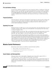
... is a disabled port. Ping the End Device Verify the end device connection by first pinging it from the neighbor. Monitor Switch Performance Review these sections when you find unidirectional link problems. UDLD supports a normal mode of incorrectly connected interfaces on the switch to help identify difficult-to-find the...For information about enabling UDLD on fiber-optic and twisted-pair links and by its Content-Addressable Memory (CAM) table. Catalyst 3560 Switch Hardware Installation Guide 4-4 OL-6337-07 If a port or interface is manually shut down on one -way traffic on the...
... is a disabled port. Ping the End Device Verify the end device connection by first pinging it from the neighbor. Monitor Switch Performance Review these sections when you find unidirectional link problems. UDLD supports a normal mode of incorrectly connected interfaces on the switch to help identify difficult-to-find the...For information about enabling UDLD on fiber-optic and twisted-pair links and by its Content-Addressable Memory (CAM) table. Catalyst 3560 Switch Hardware Installation Guide 4-4 OL-6337-07 If a port or interface is manually shut down on one -way traffic on the...

Hardware Installation Guide
Page 119
...17 shelf-mounting 24- and 12-port switches) 3-2 Catalyst 3560 Switch Hardware Installation Guide IN-5 and 12-port switches 3-8 Simple Network Management Protocol See SNMP SNMP network management platforms 1-21 software switch management 1-20 speed, troubleshooting 4-4 straight-...fiber-optic cables 4-3 link status 4-3 ping end device 4-4 port and interface settings 4-4 POST 4-1 spanning tree loops 4-4 speed, duplex, and autonegotiation 4-4 switch performance 4-4 troubleshooting spanning tree loops 4-4 W wall-mounting 24- and 12-port switches 3-17 warnings code compliance 2-4, 3-4 DC power...
...17 shelf-mounting 24- and 12-port switches) 3-2 Catalyst 3560 Switch Hardware Installation Guide IN-5 and 12-port switches 3-8 Simple Network Management Protocol See SNMP SNMP network management platforms 1-21 software switch management 1-20 speed, troubleshooting 4-4 straight-...fiber-optic cables 4-3 link status 4-3 ping end device 4-4 port and interface settings 4-4 POST 4-1 spanning tree loops 4-4 speed, duplex, and autonegotiation 4-4 switch performance 4-4 troubleshooting spanning tree loops 4-4 W wall-mounting 24- and 12-port switches 3-17 warnings code compliance 2-4, 3-4 DC power...


