
Service Manual
Page 2
... Japan COPYRIGHT © 1999 CANON INC. SPECIFICATIONS AND OTHER INFORMATION CONTAINED HEREIN MAY VARY SLIGHTLY FROM ACTUAL MACHINE VALUES OR THOSE FOUND IN ADVERTISING AND OTHER PRINTED MATTER. ANY QUESTIONS REGARDING INFORMATION CONTAINED HEREIN SHOULD BE DIRECTED TO THE COPIER SERVICE DEPARTMENT OF THE SALES COMPANY. Printed in Japan Imprimé au Japon Use of this manual should be strictly supervised...
... Japan COPYRIGHT © 1999 CANON INC. SPECIFICATIONS AND OTHER INFORMATION CONTAINED HEREIN MAY VARY SLIGHTLY FROM ACTUAL MACHINE VALUES OR THOSE FOUND IN ADVERTISING AND OTHER PRINTED MATTER. ANY QUESTIONS REGARDING INFORMATION CONTAINED HEREIN SHOULD BE DIRECTED TO THE COPIER SERVICE DEPARTMENT OF THE SALES COMPANY. Printed in Japan Imprimé au Japon Use of this manual should be strictly supervised...
Service Manual
Page 3
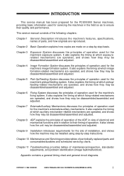
... 11 Troubleshooting provides tables of periodically replaced parts and consumables/durables and scheduled servicing charts. CANON PC800s/900s REV.0 AUG. 1999 PRINTED IN JAPAN (IMPRIME AU JAPON) i Chapter 9 Installation introduces requirements for the machine's fixing system. Appendix contains a general timing chart and general circuit diagrams. COPYRIGHT © 1999 CANON INC. Chapter 2 Basic Operation explains how copies are operated, and shows how they may be disassembled...
... 11 Troubleshooting provides tables of periodically replaced parts and consumables/durables and scheduled servicing charts. CANON PC800s/900s REV.0 AUG. 1999 PRINTED IN JAPAN (IMPRIME AU JAPON) i Chapter 9 Installation introduces requirements for the machine's fixing system. Appendix contains a general timing chart and general circuit diagrams. COPYRIGHT © 1999 CANON INC. Chapter 2 Basic Operation explains how copies are operated, and shows how they may be disassembled...
Service Manual
Page 8
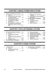
Outline 4-1 B. Measuring the Density of Paper 5-9 D. Controlling the Movement of Originals 4-16 G. DISASSEMBLY/ASSEMBLY ..... 5-18 A. OPERATIONS 6-1 A. Timing Chart for the Image Formation System 4-3 C. PICKUP/FEEDING SYSTEM.......5-1 A. Single-feeder Assembly ..... 5-31 D. CANON PC800s/900s REV.0 AUG. 1999 PRINTED IN JAPAN (IMPRIME AU JAPON) Controlling the Primary Charging Roller Bias 4-4 D. Delivery Assembly 5-36 CHAPTER 6 FIXING SYSTEM I . Fixing Assembly 6-11 vi COPYRIGHT © 1999...
Outline 4-1 B. Measuring the Density of Paper 5-9 D. Controlling the Movement of Originals 4-16 G. DISASSEMBLY/ASSEMBLY ..... 5-18 A. OPERATIONS 6-1 A. Timing Chart for the Image Formation System 4-3 C. PICKUP/FEEDING SYSTEM.......5-1 A. Single-feeder Assembly ..... 5-31 D. CANON PC800s/900s REV.0 AUG. 1999 PRINTED IN JAPAN (IMPRIME AU JAPON) Controlling the Primary Charging Roller Bias 4-4 D. Delivery Assembly 5-36 CHAPTER 6 FIXING SYSTEM I . Fixing Assembly 6-11 vi COPYRIGHT © 1999...
Service Manual
Page 10
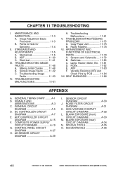
... FAULTS 11-48 A. Making Initial Checks ....... 11-48 B. Troubleshooting Image Faults 11-53 IV. Troubleshooting Malfunctions 11-61 V. Copy Paper Jam 11-75 B. Sensors and Solenoids .... 11-79 B. Lamp, Heater, Motor, Etc. 11-81 D. PCBs 11-82 E. Variable Resistors (VR) and Check Pins by PCB .......... 11-84 VII. GENERAL CIRCUIT DIAGRAM A-5 D. ADF CONTROLLER CIRCUIT DIAGRAM A-15 F. COMPOSITE POWER SUPPLY CIRCUIT DIAGRAM A-19 G. CONTROL PANEL...
... FAULTS 11-48 A. Making Initial Checks ....... 11-48 B. Troubleshooting Image Faults 11-53 IV. Troubleshooting Malfunctions 11-61 V. Copy Paper Jam 11-75 B. Sensors and Solenoids .... 11-79 B. Lamp, Heater, Motor, Etc. 11-81 D. PCBs 11-82 E. Variable Resistors (VR) and Check Pins by PCB .......... 11-84 VII. GENERAL CIRCUIT DIAGRAM A-5 D. ADF CONTROLLER CIRCUIT DIAGRAM A-15 F. COMPOSITE POWER SUPPLY CIRCUIT DIAGRAM A-19 G. CONTROL PANEL...
Service Manual
Page 13
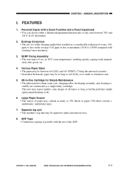
... -One Cartridge for Simple Maintenance • The photosensitive drum, toner case, charging roller, developing assembly, and cleaning assembly are constructed as a business card. 5. Personal Copier with the use of a roller charging method has resulted in a considerable reduction of paper (500-sheet cassette + multifeeder; COPYRIGHT © 1999 CANON INC. The user may be opened to 1/1000 compared with existing Canon machines). 3. Separate top unit • The machine's top unit may contain...
... -One Cartridge for Simple Maintenance • The photosensitive drum, toner case, charging roller, developing assembly, and cleaning assembly are constructed as a business card. 5. Personal Copier with the use of a roller charging method has resulted in a considerable reduction of paper (500-sheet cassette + multifeeder; COPYRIGHT © 1999 CANON INC. The user may be opened to 1/1000 compared with existing Canon machines). 3. Separate top unit • The machine's top unit may contain...
Service Manual
Page 27
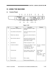
... 2 Copy density mode indicator 3 Default ratio indicator 4 Paper selection indicator*1 5 Jam indicator 6 Count/ratio indicator 7 Clear/stop key 8 Copy start key 9 Power switch Figure 1-401 Description Adjusts the density of copies or reproduction ratio. • The symbol "%" turns on and off the power. Flashes in response to standard mode. continuous copying) Stops copying or returns copying mode to a jam. • Indicates the number of copies manually. CANON PC800s/900s REV.0 AUG. 1999 PRINTED IN...
... 2 Copy density mode indicator 3 Default ratio indicator 4 Paper selection indicator*1 5 Jam indicator 6 Count/ratio indicator 7 Clear/stop key 8 Copy start key 9 Power switch Figure 1-401 Description Adjusts the density of copies or reproduction ratio. • The symbol "%" turns on and off the power. Flashes in response to standard mode. continuous copying) Stops copying or returns copying mode to a jam. • Indicates the number of copies manually. CANON PC800s/900s REV.0 AUG. 1999 PRINTED IN...
Service Manual
Page 37
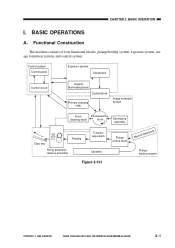
... Primary charging roller Image formation system Drum cleaning block Photosensitive drum Developing assembly Copy tray Feeding Fixing assembly/ delivery assembly Transfer/ separation Cassette Figure 2-101 Pickup control block Manual feed block Pickup/ feeding system COPYRIGHT © 1999 CANON INC. BASIC OPERATIONS A. CANON PC800s/900s REV.0 AUG. 1999 PRINTED IN JAPAN (IMPRIME AU JAPON) 2-1 Functional Construction The machine consists of four functional blocks: pickup/feeding system, exposure system, image...
... Primary charging roller Image formation system Drum cleaning block Photosensitive drum Developing assembly Copy tray Feeding Fixing assembly/ delivery assembly Transfer/ separation Cassette Figure 2-101 Pickup control block Manual feed block Pickup/ feeding system COPYRIGHT © 1999 CANON INC. BASIC OPERATIONS A. CANON PC800s/900s REV.0 AUG. 1999 PRINTED IN JAPAN (IMPRIME AU JAPON) 2-1 Functional Construction The machine consists of four functional blocks: pickup/feeding system, exposure system, image...
Service Manual
Page 117
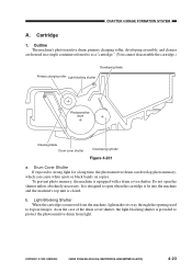
... photosensitive drum from the machine, light makes its way through the opening used to strong light for a long time, the photosensitive drum can develop photo memory, which can cause white spots or black bands on copies. b. As in a single container referred to as a "cartridge." (You cannot disassemble the cartridge.) Developing blade Primary charging roller Light-blocking shutter Photosensitive drum Cleaning blade Drum cover shutter Developing cylinder Figure 4-201 a. Cartridge 1. Drum...
... photosensitive drum from the machine, light makes its way through the opening used to strong light for a long time, the photosensitive drum can develop photo memory, which can cause white spots or black bands on copies. b. As in a single container referred to as a "cartridge." (You cannot disassemble the cartridge.) Developing blade Primary charging roller Light-blocking shutter Photosensitive drum Cleaning blade Drum cover shutter Developing cylinder Figure 4-201 a. Cartridge 1. Drum...
Service Manual
Page 142
... necessary, cut the harnessband. 6. CANON PC800s/900s REV.0 AUG. 1999 PRINTED IN JAPAN (IMPRIME AU JAPON) A few of its part removed. 7. Do not use any of the screws used to ensure electrical continuity.) 5. DISASSEMBLY/ASSEMBLY As needed, disassemble/assemble the machine with any screws indiscriminately. 5-18 COPYRIGHT © 1999 CANON INC. CHAPTER 5 PICK-UP/FEEDING SYSTEM II. Use the washers where necessary. (The...
... necessary, cut the harnessband. 6. CANON PC800s/900s REV.0 AUG. 1999 PRINTED IN JAPAN (IMPRIME AU JAPON) A few of its part removed. 7. Do not use any of the screws used to ensure electrical continuity.) 5. DISASSEMBLY/ASSEMBLY As needed, disassemble/assemble the machine with any screws indiscriminately. 5-18 COPYRIGHT © 1999 CANON INC. CHAPTER 5 PICK-UP/FEEDING SYSTEM II. Use the washers where necessary. (The...
Service Manual
Page 254
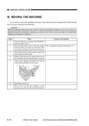
... Checks and remarks Turn on the manual feed tray. feed tray; Take out the shipping attachments [1] and [2] stored in which the shipping attachment is not too hot. Turn off the power switch, and disconnect the power plug from the outlet. CANON PC800s/900s REV.0 AUG. 1999 PRINTED IN JAPAN (IMPRIME AU JAPON) Press the Paper Select key to select 70%. Pull the open the machine's top unit...
... Checks and remarks Turn on the manual feed tray. feed tray; Take out the shipping attachments [1] and [2] stored in which the shipping attachment is not too hot. Turn off the power switch, and disconnect the power plug from the outlet. CANON PC800s/900s REV.0 AUG. 1999 PRINTED IN JAPAN (IMPRIME AU JAPON) Press the Paper Select key to select 70%. Pull the open the machine's top unit...
Service Manual
Page 258
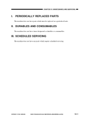
CHAPTER 10 MAINTENANCE AND SERVICING I. II. III. COPYRIGHT © 1999 CANON INC. DURABLES AND CONSUMABLES The machine does not have any parts which must be replaced on a periodical basis. SCHEDULED SERVICING The machine does not have items designated as durables or consumables. PERIODICALLY REPLACED PARTS The machine does not have parts which require scheduled servicing. CANON PC800s/900s REV.0 AUG. 1999 PRINTED IN JAPAN (IMPRIME AU JAPON) 10-1
CHAPTER 10 MAINTENANCE AND SERVICING I. II. III. COPYRIGHT © 1999 CANON INC. DURABLES AND CONSUMABLES The machine does not have any parts which must be replaced on a periodical basis. SCHEDULED SERVICING The machine does not have items designated as durables or consumables. PERIODICALLY REPLACED PARTS The machine does not have parts which require scheduled servicing. CANON PC800s/900s REV.0 AUG. 1999 PRINTED IN JAPAN (IMPRIME AU JAPON) 10-1
Service Manual
Page 262
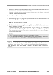
... alone in mind: Caution: 1. Try leaving the machine alone as long as by opening the shutter for the photosensitive drum shutter. Try to excess vibration or impact. CANON PC800s/900s REV.0 AUG. 1999 PRINTED IN JAPAN (IMPRIME AU JAPON) 10-5 Do not disassemble the cartridge. Do not leave it with a flannel cloth coated with toner. CHAPTER 10 MAINTENANCE AND SERVICING c.
... alone in mind: Caution: 1. Try leaving the machine alone as long as by opening the shutter for the photosensitive drum shutter. Try to excess vibration or impact. CANON PC800s/900s REV.0 AUG. 1999 PRINTED IN JAPAN (IMPRIME AU JAPON) 10-5 Do not disassemble the cartridge. Do not leave it with a flannel cloth coated with toner. CHAPTER 10 MAINTENANCE AND SERVICING c.
Service Manual
Page 264
... PCB .......... 11-84 VII. Making Initial Checks ....... 11-48 B. TROUBLESHOOTING MALFUNCTIONS 11-61 A. Copy Paper Jam 11-75 B. Lamp, Heater, Motor, Etc. 11-81 D. CANON PC800s/900s REV.0 AUG. 1999 PRINTED IN JAPAN (IMPRIME AU JAPON) Faulty Feeding 11-78 VI. ADF 11-83 F. SELF DIAGNOSIS 11-86 COPYRIGHT © 1999 CANON INC. CHAPTER 11 TROUBLESHOOTING I. Switches 11-80 C. Sensors and Solenoids .... 11-79...
... PCB .......... 11-84 VII. Making Initial Checks ....... 11-48 B. TROUBLESHOOTING MALFUNCTIONS 11-61 A. Copy Paper Jam 11-75 B. Lamp, Heater, Motor, Etc. 11-81 D. CANON PC800s/900s REV.0 AUG. 1999 PRINTED IN JAPAN (IMPRIME AU JAPON) Faulty Feeding 11-78 VI. ADF 11-83 F. SELF DIAGNOSIS 11-86 COPYRIGHT © 1999 CANON INC. CHAPTER 11 TROUBLESHOOTING I. Switches 11-80 C. Sensors and Solenoids .... 11-79...
Service Manual
Page 318
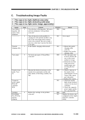
... charging roller Copy paper Transfer lower guide, Varistor Composite power supply PCB, DC controller PCB Cartridge Developing bias, Developing bias terminal Step 1 2 3 4 5 6 Checks Clean the lens, reflecting plate, AE sensor, and static eliminator. Turn off the power in contact with a metal part (side plate). 2. Is the problem corrected? COPYRIGHT © 1999 CANON INC. Mount the transfer charging roller correctly. 2. CANON PC800s/900s REV.0 AUG. 1999 PRINTED IN...
... charging roller Copy paper Transfer lower guide, Varistor Composite power supply PCB, DC controller PCB Cartridge Developing bias, Developing bias terminal Step 1 2 3 4 5 6 Checks Clean the lens, reflecting plate, AE sensor, and static eliminator. Turn off the power in contact with a metal part (side plate). 2. Is the problem corrected? COPYRIGHT © 1999 CANON INC. Mount the transfer charging roller correctly. 2. CANON PC800s/900s REV.0 AUG. 1999 PRINTED IN...
Service Manual
Page 319
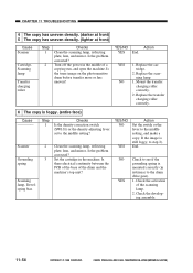
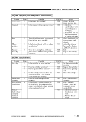
... the density correction switch (SW101) or the density adjusting lever set to step 2). Is the problem corrected? CHAPTER 11 TROUBLESHOOTING 4 The copy has uneven density. (darker at front) 5 The copy has uneven density. (lighter at front) Cause Scanner Cartridge, Scanning lamp Transfer charging roller Step 1 2 Checks Clean the scanning lamp, reflecting plate, lens, and mirror. YES 1. CANON PC800s/900s REV.0 AUG. 1999 PRINTED IN JAPAN...
... the density correction switch (SW101) or the density adjusting lever set to step 2). Is the problem corrected? CHAPTER 11 TROUBLESHOOTING 4 The copy has uneven density. (darker at front) 5 The copy has uneven density. (lighter at front) Cause Scanner Cartridge, Scanning lamp Transfer charging roller Step 1 2 Checks Clean the scanning lamp, reflecting plate, lens, and mirror. YES 1. CANON PC800s/900s REV.0 AUG. 1999 PRINTED IN JAPAN...
Service Manual
Page 320
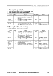
... Scanner Transfer guide assembly Cartridge Step 1 2 Checks Clean the scanning lamp, reflecting plate, lens, and mirror. COPYRIGHT © 1999 CANON INC. CHAPTER 11 TROUBLESHOOTING 7 The copy is running out of a copying run, and open the machine's top unit. Clean the transfer guide assembly. Shake the cartridge several times. YES End. Cartridge YES/NO Action YES Check the fixing assembly. YES End. Is the problem corrected? 3 Take out and then set the cartridge...
... Scanner Transfer guide assembly Cartridge Step 1 2 Checks Clean the scanning lamp, reflecting plate, lens, and mirror. COPYRIGHT © 1999 CANON INC. CHAPTER 11 TROUBLESHOOTING 7 The copy is running out of a copying run, and open the machine's top unit. Clean the transfer guide assembly. Shake the cartridge several times. YES End. Cartridge YES/NO Action YES Check the fixing assembly. YES End. Is the problem corrected? 3 Take out and then set the cartridge...
Service Manual
Page 324
.... Check the lens rail for electrical continuity. 2. Replace the cartridge COPYRIGHT © 1999 CANON INC. Does the drum cover shutter open seal been removed? Check the cartridge. NO 1. Turn off the copyboard glass? CHAPTER 11 TROUBLESHOOTING 20 The copy has poor sharpness. (out-of-focus) Cause Original Lens Mirror position Scanner Cartridge Step 1 2 3 4 5 Checks Is the image also too light? Is the horizontal ratio in the machine?
.... Check the lens rail for electrical continuity. 2. Replace the cartridge COPYRIGHT © 1999 CANON INC. Does the drum cover shutter open seal been removed? Check the cartridge. NO 1. Turn off the copyboard glass? CHAPTER 11 TROUBLESHOOTING 20 The copy has poor sharpness. (out-of-focus) Cause Original Lens Mirror position Scanner Cartridge Step 1 2 3 4 5 Checks Is the image also too light? Is the horizontal ratio in the machine?
Service Manual
Page 330
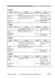
... position sensor (PS2) normal? (For instructions on when the Copy Start key is turned on the DC controller PCB to use a frequency stabilizer. Replace the DC controller PCB. 9 E220 Cause Composite power supply PCB DC controller PCB Step 1 2 Checks Does the scanning lamp turn on the power switch. YES/NO NO YES Action See "The scanning lamp fails to turn on how to check the...
... position sensor (PS2) normal? (For instructions on when the Copy Start key is turned on the DC controller PCB to use a frequency stabilizer. Replace the DC controller PCB. 9 E220 Cause Composite power supply PCB DC controller PCB Step 1 2 Checks Does the scanning lamp turn on the power switch. YES/NO NO YES Action See "The scanning lamp fails to turn on how to check the...
Service Manual
Page 336
... power supply PCB Pre-registration roller paper sensor (Q751) Scanner/lens drive motor (M2) DC controller PCB Step 1 2 3 4 5 Checks Is the scanner drive cable routed correctly? NO Replace the DC controller PCB. 20 The registration roller fails to rotate when the Copy Start key is pressed? Yes/No No Action See "The main motor fails to move smoothly? CHAPTER 11 TROUBLESHOOTING...
... power supply PCB Pre-registration roller paper sensor (Q751) Scanner/lens drive motor (M2) DC controller PCB Step 1 2 3 4 5 Checks Is the scanner drive cable routed correctly? NO Replace the DC controller PCB. 20 The registration roller fails to rotate when the Copy Start key is pressed? Yes/No No Action See "The main motor fails to move smoothly? CHAPTER 11 TROUBLESHOOTING...
Service Manual
Page 339
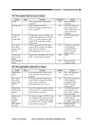
.... 26 The "Jam" message fails to turn off . if normal, replace the sensor in step 1 normal? (For instructions on how to check the photointerrupters, see p. 11-47.) YES/NO YES NO YES Action Remove the jam paper. Cause Cassette Lens cable, Pulley, Rail DC power supply Vertical path roller paper sensor (PS4) Control panel PCB DC controller PCB Step 1 2 3 4 5 Checks Is the cassette set correctly? See...
.... 26 The "Jam" message fails to turn off . if normal, replace the sensor in step 1 normal? (For instructions on how to check the photointerrupters, see p. 11-47.) YES/NO YES NO YES Action Remove the jam paper. Cause Cassette Lens cable, Pulley, Rail DC power supply Vertical path roller paper sensor (PS4) Control panel PCB DC controller PCB Step 1 2 3 4 5 Checks Is the cassette set correctly? See...


