
Users Manual - English
Page 5
... 2-1 Printer Carton 2-1 Toner Cartridge 2-2 General View 2-3 Operating and Storage Environment 2-4 Power Supply 2-4 Environment 2-4 SETTING UP THE PRINTER 2-5 Opening and Closing the Printer 2-5 Removing the Protective Parts 2-6 Installing the Toner Cartridge 2-7 Loading Paper in the Paper Cassette 2-11 Connecting the Printer to Your Computer 2-17 Turning the Printer On and Off 2-19...
... 2-1 Printer Carton 2-1 Toner Cartridge 2-2 General View 2-3 Operating and Storage Environment 2-4 Power Supply 2-4 Environment 2-4 SETTING UP THE PRINTER 2-5 Opening and Closing the Printer 2-5 Removing the Protective Parts 2-6 Installing the Toner Cartridge 2-7 Loading Paper in the Paper Cassette 2-11 Connecting the Printer to Your Computer 2-17 Turning the Printer On and Off 2-19...

Users Manual - English
Page 11
...plug should be determined by turning the equipment off and on a circuit different from that to correct the interference by Brother Industries, Ltd. As an International Energy Star partner, Brother Industries, Ltd. only) This equipment has been tested and found to comply with the limits for a Class B...Statement (For HL-1660 series only) The purpose of the following measures: t Reorient or relocate the receiving antenna. could void the user's authority to the U.S.A. This equipment generates, uses, and can be used in accordance with FCC standards, which are designed to Part 15 of ...
...plug should be determined by turning the equipment off and on a circuit different from that to correct the interference by Brother Industries, Ltd. As an International Energy Star partner, Brother Industries, Ltd. only) This equipment has been tested and found to comply with the limits for a Class B...Statement (For HL-1660 series only) The purpose of the following measures: t Reorient or relocate the receiving antenna. could void the user's authority to the U.S.A. This equipment generates, uses, and can be used in accordance with FCC standards, which are designed to Part 15 of ...
Users Manual - English
Page 27
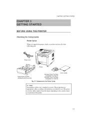
... Checking the Components Printer Carton When you unpack the printer, check to see that you intend to the interface you have all of the following parts. Please purchase an appropriate cable according to use. The power cord may differ slightly from this figure depending on the country where you purchased the...
... Checking the Components Printer Carton When you unpack the printer, check to see that you intend to the interface you have all of the following parts. Please purchase an appropriate cable according to use. The power cord may differ slightly from this figure depending on the country where you purchased the...
Users Manual - English
Page 32
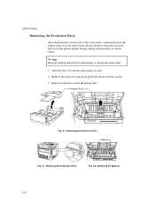
... spacers from inside the printer and the cassette. 3. Remove the protective parts from the fixing roller. Protective Parts Fig. 2-7 Removing the Protective Parts Spacers Fig. 2-7 Removing the Protective Parts Fig. 2-8 Removing the Spacers 2-6 Remove the protective parts that you have all of the correct parts, temporarily place the printer where you can easily reach all packing...
... spacers from inside the printer and the cassette. 3. Remove the protective parts from the fixing roller. Protective Parts Fig. 2-7 Removing the Protective Parts Spacers Fig. 2-7 Removing the Protective Parts Fig. 2-8 Removing the Spacers 2-6 Remove the protective parts that you have all of the correct parts, temporarily place the printer where you can easily reach all packing...

Users Manual - English
Page 33
... toner cartridge installed, the display shows the following operator call message to prompt you turn it up-side down. • Do not touch the shaded parts shown below. • Do not open the drum shutter otherwise the toner or drum is set at about 5% coverage (if the print density is adversely...
... toner cartridge installed, the display shows the following operator call message to prompt you turn it up-side down. • Do not touch the shaded parts shown below. • Do not open the drum shutter otherwise the toner or drum is set at about 5% coverage (if the print density is adversely...
Users Manual - English
Page 63
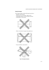
CHAPTER 3 BEFORE WORKING WITH THE PRINTER Using Envelopes Avoid using envelopes with the following characteristics: • Smooth or shiny surfaces • Protection cover at envelopes' adhesive parts • Sealing flaps that have not been folded at purchase • Sealing flaps as shown below • Three or more layers of paper in the marked area • Each side folded as shown below Fig. 3-3 Envelope Information 3-13
CHAPTER 3 BEFORE WORKING WITH THE PRINTER Using Envelopes Avoid using envelopes with the following characteristics: • Smooth or shiny surfaces • Protection cover at envelopes' adhesive parts • Sealing flaps that have not been folded at purchase • Sealing flaps as shown below • Three or more layers of paper in the marked area • Each side folded as shown below Fig. 3-3 Envelope Information 3-13
Users Manual - English
Page 98
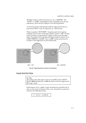
...pattern are too complex to print, the printer may print them out in the left figure below. The pattern will be better depending on part of lines. Choose an HRC setting and perform the test print so that stepped lines become unnoticeable. If print images are unsmoothed or stepped... as shown in parts or only on the selected print density. Choose the best setting for clear and crisp printouts. For operation, see "TEST Switch." When you ...
...pattern are too complex to print, the printer may print them out in the left figure below. The pattern will be better depending on part of lines. Choose an HRC setting and perform the test print so that stepped lines become unnoticeable. If print images are unsmoothed or stepped... as shown in parts or only on the selected print density. Choose the best setting for clear and crisp printouts. For operation, see "TEST Switch." When you ...

Users Manual - English
Page 103
... select "SAVE DATA" and you to ensure as much capacity as PCL data, BR-Script 2 data, and command strings can clear this error occurs, only part of the printer. SET KEY --> END This message prompts you press the SET switch, the display shows the following : • If the received data exceeds...
... select "SAVE DATA" and you to ensure as much capacity as PCL data, BR-Script 2 data, and command strings can clear this error occurs, only part of the printer. SET KEY --> END This message prompts you press the SET switch, the display shows the following : • If the received data exceeds...

Users Manual - English
Page 120
..." accordingly. PITCH= 16.66 Press the SET switch to make the displayed selection effective. Press the SET switch. Press the SET switch to the decimal part of Symbol/Character Sets" on the display. Press the v or w switch until the desired symbol set appears on the display. When you have selected fixed...
..." accordingly. PITCH= 16.66 Press the SET switch to make the displayed selection effective. Press the SET switch. Press the SET switch to the decimal part of Symbol/Character Sets" on the display. Press the v or w switch until the desired symbol set appears on the display. When you have selected fixed...

Users Manual - English
Page 124
... mode, the display first shows the current character set the font size by the character pitch (width). The following displays show "PITCH" to the decimal part of the number. Press the v or w switch until the desired font size appears on the display. PITCH= 16.66 Press the SET switch to make...
... mode, the display first shows the current character set the font size by the character pitch (width). The following displays show "PITCH" to the decimal part of the number. Press the v or w switch until the desired font size appears on the display. PITCH= 16.66 Press the SET switch to make...
Users Manual - English
Page 144
... from a printing job in a shorter time if you use this feature than when you send too many pages to be stored in the printer memory, part or all of the set the number of Copies to set the copy print quantity with the asterisk. An asterisk appears at 3, the display may...
... from a printing job in a shorter time if you use this feature than when you send too many pages to be stored in the printer memory, part or all of the set the number of Copies to set the copy print quantity with the asterisk. An asterisk appears at 3, the display may...

Users Manual - English
Page 193
... Pat-top ,he come . Here come v ,he come . One thing I can tell you is you go to be free. USER'S GUIDE s Dropout If nothing or part of High Resolution Control 7-18 One thing I can tell you is you go to be free. AA One thing I can tell you is you go...
... Pat-top ,he come . Here come v ,he come . One thing I can tell you is you go to be free. USER'S GUIDE s Dropout If nothing or part of High Resolution Control 7-18 One thing I can tell you is you go to be free. AA One thing I can tell you is you go...
Users Manual - English
Page 201
... TRANSPARENCIES The printer will print on most type of labels and transparencies designed for the quality and performance of labels and transparencies lies with any part of the printer, because the label stock may stick to the drum or rollers and cause jams and print quality problems. No adhesive should be...
... TRANSPARENCIES The printer will print on most type of labels and transparencies designed for the quality and performance of labels and transparencies lies with any part of the printer, because the label stock may stick to the drum or rollers and cause jams and print quality problems. No adhesive should be...

Users Manual - English
Page 257
... primary font: 4-50 print density: 4-46 print start position: 4-23 printer driver: 3-1 printer emulation: 3-1 printer settings: 3-10, 4-86 printer status message: 4-2 printer test: 4-86 protective parts: 2-6 INDEX Q quick exit switch: 4-6 R READY lamp: 4-4 rear access cover: 2-3, 7-8 rear paper slit: 3-17 reprint: 1-9, 4-61 reset mode: 4-78 RESET switch: 4-78 resolution: 1-4, 4-29 resolution mode...
... primary font: 4-50 print density: 4-46 print start position: 4-23 printer driver: 3-1 printer emulation: 3-1 printer settings: 3-10, 4-86 printer status message: 4-2 printer test: 4-86 protective parts: 2-6 INDEX Q quick exit switch: 4-6 R READY lamp: 4-4 rear access cover: 2-3, 7-8 rear paper slit: 3-17 reprint: 1-9, 4-61 reset mode: 4-78 RESET switch: 4-78 resolution: 1-4, 4-29 resolution mode...

Service Manual
Page 2
No part this publication may be reproduced in any form or by any means without permission in writing from the publisher. Trademarks: • BR-Script, and DX-1600 are registered trademarks of Brother Industries, Ltd. • Centronics is a registered trademark of Genicom... Corporation. • PostScrip is a registered trademark of Adobe Systems Incorporated. • IBM Proprinter XL is a registered trademark of International Business Machines Corporation. • EPSON ...
No part this publication may be reproduced in any form or by any means without permission in writing from the publisher. Trademarks: • BR-Script, and DX-1600 are registered trademarks of Brother Industries, Ltd. • Centronics is a registered trademark of Genicom... Corporation. • PostScrip is a registered trademark of Adobe Systems Incorporated. • IBM Proprinter XL is a registered trademark of International Business Machines Corporation. • EPSON ...

Service Manual
Page 3
... for image defects, troubleshooting for a suitable location, disassembling and reassembling procedure of the mechanical system and the electrical system, and their timing. Maintenance and Servicing Parts replacement schedule, list of the product.
... for image defects, troubleshooting for a suitable location, disassembling and reassembling procedure of the mechanical system and the electrical system, and their timing. Maintenance and Servicing Parts replacement schedule, list of the product.

Service Manual
Page 4
... ...II-5 3.2.1 Electrostatic latent image formation stage II-6 3.2.2 Developing stage II-8 3.2.3 Transfer stage II-9 3.2.4 Fixing stage II-10 3.2.5 Drum cleaning stage II-10 3.3 Operation ...II-11 4. PARTS OF THE PRINTER I-8 4.1 External Views ...I-8 4.2 Cross Sectional View I GENERAL 1. LASER/SCANNER SYSTEM II-4 3. CONTENTS CHAPTER I -9 5. SAFETY INFORMATION ...I-6 3.1 Laser Safety (110 - 120V Model only I-6 3.2 CDRH Regulations...
... ...II-5 3.2.1 Electrostatic latent image formation stage II-6 3.2.2 Developing stage II-8 3.2.3 Transfer stage II-9 3.2.4 Fixing stage II-10 3.2.5 Drum cleaning stage II-10 3.3 Operation ...II-11 4. PARTS OF THE PRINTER I-8 4.1 External Views ...I-8 4.2 Cross Sectional View I GENERAL 1. LASER/SCANNER SYSTEM II-4 3. CONTENTS CHAPTER I -9 5. SAFETY INFORMATION ...I-6 3.1 Laser Safety (110 - 120V Model only I-6 3.2 CDRH Regulations...

Service Manual
Page 6
TROUBLESHOOTING OF MALFUNCTIONS VI-11 5. Engine Block Diagram ...A-1 2. Main PCB Circuitry Diagram (4/7 A-6 7. Main PCB Circuitry Diagram (6/7 A-8 9. Scanner LD PCB Circuitry Diagram (1/1 A-11 iii PERIODICAL REPLACEMENT PARTS V-1 2. CONSUMABLE PARTS STANDARD ENDURANCETABLE V-1 3. INTRODUCTION ...VI-1 1.1 Initial Check ...VI-1 1.2 Basic Procedure ...VI-2 2. IMAGE DEFECTS ...VI-3 3.1 Image Defect Examples VI-3 3.2 Troubleshooting Image Defects VI-4 4. Main PCB Circuitry Diagram...
TROUBLESHOOTING OF MALFUNCTIONS VI-11 5. Engine Block Diagram ...A-1 2. Main PCB Circuitry Diagram (4/7 A-6 7. Main PCB Circuitry Diagram (6/7 A-8 9. Scanner LD PCB Circuitry Diagram (1/1 A-11 iii PERIODICAL REPLACEMENT PARTS V-1 2. CONSUMABLE PARTS STANDARD ENDURANCETABLE V-1 3. INTRODUCTION ...VI-1 1.1 Initial Check ...VI-1 1.2 Basic Procedure ...VI-2 2. IMAGE DEFECTS ...VI-3 3.1 Image Defect Examples VI-3 3.2 Troubleshooting Image Defects VI-4 4. Main PCB Circuitry Diagram...
Service Manual
Page 14
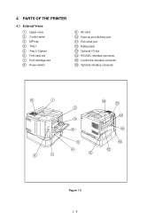
PARTS OF THE PRINTER 4.1 External Views 1 Upper cover 2 Control panel 3 MP tray 4 Tray 1 5 Tray 2 (Option) 6 Font card slot 7 Font cartridge slot 8 Power switch 9 AC inlet 10 Face-up print delivery port 11 Fan outlet port 12 Rating label 13 Optional I/O slot 14 RS-232C interface connector 15 Centronics interface connector 16 Optional interface connector 11 1 6 7 10 15 2 13 3 8 14 5 4 9 16 12 Figure 1.4 I - 8 4.
PARTS OF THE PRINTER 4.1 External Views 1 Upper cover 2 Control panel 3 MP tray 4 Tray 1 5 Tray 2 (Option) 6 Font card slot 7 Font cartridge slot 8 Power switch 9 AC inlet 10 Face-up print delivery port 11 Fan outlet port 12 Rating label 13 Optional I/O slot 14 RS-232C interface connector 15 Centronics interface connector 16 Optional interface connector 11 1 6 7 10 15 2 13 3 8 14 5 4 9 16 12 Figure 1.4 I - 8 4.

Service Manual
Page 21
...paper by the printer has a seamless photosensitive drum with the structure shown in Figure 2.5. The image formation system is the main part of the printer. The printing process can be divided into the engine controller circuit as shown in Figure 2.6. IMAGE FORMATION SYSTEM... is composed of the photosensitive drum the charging unit, the developing unit and the cleaning unit. 3.2 Printing Process The major part of an organic photoconductor (OPC); Laser beam Cartridge Primary charging roller Blade Cleaning blade Photosensitive drum Developing cylinder Paper Transfer charging ...
...paper by the printer has a seamless photosensitive drum with the structure shown in Figure 2.5. The image formation system is the main part of the printer. The printing process can be divided into the engine controller circuit as shown in Figure 2.6. IMAGE FORMATION SYSTEM... is composed of the photosensitive drum the charging unit, the developing unit and the cleaning unit. 3.2 Printing Process The major part of an organic photoconductor (OPC); Laser beam Cartridge Primary charging roller Blade Cleaning blade Photosensitive drum Developing cylinder Paper Transfer charging ...


