Owners Guide
Page 2
...owner's guide carefully. CAUTION: No naked flame sources, such as lighted candles, should be placed on the rear panel of the Acoustimass® module: The lightning flash with arrowhead symbol, within an equilateral triangle, is intended to alert the user to the presence of important operating and maintenance instruction...USAGER. NO USER-SERVICABLE PARTS INSIDE. Please read this owner's guide Please take the time to read and follow this system to dripping or splashing, and objects filled with the monitor. It will help you set up and operate your owner's guide for future ...
...owner's guide carefully. CAUTION: No naked flame sources, such as lighted candles, should be placed on the rear panel of the Acoustimass® module: The lightning flash with arrowhead symbol, within an equilateral triangle, is intended to alert the user to the presence of important operating and maintenance instruction...USAGER. NO USER-SERVICABLE PARTS INSIDE. Please read this owner's guide Please take the time to read and follow this system to dripping or splashing, and objects filled with the monitor. It will help you set up and operate your owner's guide for future ...
Owners Guide
Page 3
... a different circuit than the one wider than the other. English Important Safety Instructions 1. for future reference. 3. Follow all warnings - Do not block any heat sources, such as power-supply cord or plug is no guarantee that water or moisture are encouraged to try to radio communications. Install in accordance with one to Part 15 of the receiver or radio remote control could...
... a different circuit than the one wider than the other. English Important Safety Instructions 1. for future reference. 3. Follow all warnings - Do not block any heat sources, such as power-supply cord or plug is no guarantee that water or moisture are encouraged to try to radio communications. Install in accordance with one to Part 15 of the receiver or radio remote control could...
Owners Guide
Page 4
... antenna-discharge unit, connection to the antenna grounding illustration on the product. 19. Use Proper Power Sources - English Important Safety Instructions 18. Do not install external antennas near overhead power lines or other electric light or power circuits, nor where an antenna can fall into a proper power source, as described in the operating instructions or as per National Electrical Code, ANSI/NFPA...
... antenna-discharge unit, connection to the antenna grounding illustration on the product. 19. Use Proper Power Sources - English Important Safety Instructions 18. Do not install external antennas near overhead power lines or other electric light or power circuits, nor where an antenna can fall into a proper power source, as described in the operating instructions or as per National Electrical Code, ANSI/NFPA...
Owners Guide
Page 5
... Companion® 3 Multimedia Speaker System 4 System Setup 5 Unpacking 5 Selecting a location for your Companion 3 Multimedia Speaker System 6 Positioning the Acoustimass® module 6 Positioning the satellite speakers 7 Making connections 10 To Connect 10 To make the final connection and power the system 10 Additional Connections 10 Operation 11 Operating the Companion 3 multimedia speaker system 11 Troubleshooting 12 Troubleshooting 12 Reference 13 Maintaining the Companion® 3 Multimedia Speaker System 13 Cleaning the system 13 Limited Warranty period 13 Technical...
... Companion® 3 Multimedia Speaker System 4 System Setup 5 Unpacking 5 Selecting a location for your Companion 3 Multimedia Speaker System 6 Positioning the Acoustimass® module 6 Positioning the satellite speakers 7 Making connections 10 To Connect 10 To make the final connection and power the system 10 Additional Connections 10 Operation 11 Operating the Companion 3 multimedia speaker system 11 Troubleshooting 12 Troubleshooting 12 Reference 13 Maintaining the Companion® 3 Multimedia Speaker System 13 Cleaning the system 13 Limited Warranty period 13 Technical...
Owners Guide
Page 6
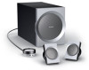
... together. • Control pod allows you to control system volume and connect headphones or portable audio players. • Integrated signal processing provides full, rich sound at all listening levels. • Auxiliary input jack lets you for your computer and a variety of other audio source. 4 Bose designed this system a superior choice for purchasing the Bose® Companion 3 multimedia speaker system. Its unique features make this amplified speaker system to include...
... together. • Control pod allows you to control system volume and connect headphones or portable audio players. • Integrated signal processing provides full, rich sound at all listening levels. • Auxiliary input jack lets you for your computer and a variety of other audio source. 4 Bose designed this system a superior choice for purchasing the Bose® Companion 3 multimedia speaker system. Its unique features make this amplified speaker system to include...
Owners Guide
Page 7
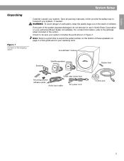
... Bose Corporation or your system, if needed. Check to the address sheet included in Figure 1. Acoustimass® module Brackets Satellite speakers Rubber feet Small clear rubber feet Mounting bracket adhesive pads Audio input cable AC power cord Control pod 5 Note: Now is a good time to transport your authorized Bose® dealer immediately. English Unpacking Figure 1 Contents of this guide and on your warranty card...
... Bose Corporation or your system, if needed. Check to the address sheet included in Figure 1. Acoustimass® module Brackets Satellite speakers Rubber feet Small clear rubber feet Mounting bracket adhesive pads Audio input cable AC power cord Control pod 5 Note: Now is a good time to transport your authorized Bose® dealer immediately. English Unpacking Figure 1 Contents of this guide and on your warranty card...
Owners Guide
Page 8
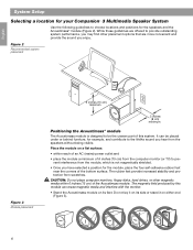
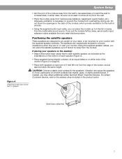
...Setup Selecting a location for your Companion® 3 Multimedia Speaker System Use the following guidelines to choose locations and positions for the module, place the four self-adhesive rubber feet near the corners of the bottom surface. The rubber feet provide increased stability and protection from the computer monitor...the Acoustimass® module The Acoustimass module is not magnetically shielded. • Once you may find other magnetic media within reach of an AC (mains) power outlet and • place the module a minimum of 6 inches (15 cm) from scratches. While these guidelines...
...Setup Selecting a location for your Companion® 3 Multimedia Speaker System Use the following guidelines to choose locations and positions for the module, place the four self-adhesive rubber feet near the corners of the bottom surface. The rubber feet provide increased stability and protection from the computer monitor...the Acoustimass® module The Acoustimass module is not magnetically shielded. • Once you may find other magnetic media within reach of an AC (mains) power outlet and • place the module a minimum of 6 inches (15 cm) from scratches. While these guidelines...
Owners Guide
Page 9
...: Choose a stable, level surface for the built-in circuitry. • Using the supplied audio input cable, you can place the satellite speakers up to prevent interference when they are magnetically shielded to 6 feet (2 m) away from the multimedia sound source. English System Setup Figure 4 Attaching small clear rubber feet to speaker • Aim the port of the module, which provide ventilation...
...: Choose a stable, level surface for the built-in circuitry. • Using the supplied audio input cable, you can place the satellite speakers up to prevent interference when they are magnetically shielded to 6 feet (2 m) away from the multimedia sound source. English System Setup Figure 4 Attaching small clear rubber feet to speaker • Aim the port of the module, which provide ventilation...
Owners Guide
Page 10
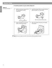
Note: Be sure to the right speaker bracket (marked R). 2. Peel off one side of the open bracket. Mounting bracket adhesive pads 4. Move the bracket along the cord toward the speaker. Insert the speaker wire into the center of the mounting adhesive pad and attach it to the bracket. English System Setup Figure 5 Mounting the bracket If mounting speakers on your monitor (Figure 5): 1. Pad Small clear rubber foot 3. Attach a small clear rubber foot to wipe the monitor clean before affixing speaker brackets. 8
Note: Be sure to the right speaker bracket (marked R). 2. Peel off one side of the open bracket. Mounting bracket adhesive pads 4. Move the bracket along the cord toward the speaker. Insert the speaker wire into the center of the mounting adhesive pad and attach it to the bracket. English System Setup Figure 5 Mounting the bracket If mounting speakers on your monitor (Figure 5): 1. Pad Small clear rubber foot 3. Attach a small clear rubber foot to wipe the monitor clean before affixing speaker brackets. 8
Owners Guide
Page 11
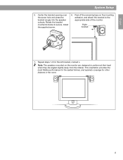
Install the supplied screw. 6. Peel off the remaining tape on the monitor are designed to the appropriate side of the monitor. Right bracket 7. Note: The speakers mounted on the mounting adhesive, and attach the bracket to perform at their best when they are angled slightly away from the listener. English System Setup 5. This orientation provides the most lifelike performance...
Install the supplied screw. 6. Peel off the remaining tape on the monitor are designed to the appropriate side of the monitor. Right bracket 7. Note: The speakers mounted on the mounting adhesive, and attach the bracket to perform at their best when they are angled slightly away from the listener. English System Setup 5. This orientation provides the most lifelike performance...
Owners Guide
Page 12
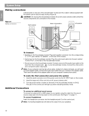
... control pod. Insert the small connector end of the module. • Control pod to the adapter cable. The LED on your system, plug the cable from your computer only has two phono jacks, instead of the audio input cable to the Acoustimass module; Note: Connecting headphones will need an audio adapter cable. To make the final connection and power the system 1. Connect one end of a stereo mini jack, you will silence the output from the sound source output jack...
... control pod. Insert the small connector end of the module. • Control pod to the adapter cable. The LED on your system, plug the cable from your computer only has two phono jacks, instead of the audio input cable to the Acoustimass module; Note: Connecting headphones will need an audio adapter cable. To make the final connection and power the system 1. Connect one end of a stereo mini jack, you will silence the output from the sound source output jack...
Owners Guide
Page 13
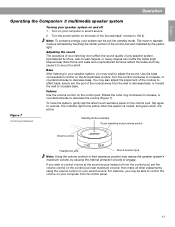
... the system, gently tap the silver touch-sensitive panel on your sound source. Figure 7 Control pod features Standby/Active indicator Touch-sensitive mute/unmute switch Volume control Headphone jack Sound source input Note: Using the volume controls in their maximum position may reduce the speaker system's maximum volume, by the yellow light. then make all other adjustments using the volume control on the control pod. Volume Use the volume control on the Acoustimass module. If you may...
... the system, gently tap the silver touch-sensitive panel on your sound source. Figure 7 Control pod features Standby/Active indicator Touch-sensitive mute/unmute switch Volume control Headphone jack Sound source input Note: Using the volume controls in their maximum position may reduce the speaker system's maximum volume, by the yellow light. then make all other adjustments using the volume control on the control pod. Volume Use the volume control on the Acoustimass module. If you may...
Owners Guide
Page 14
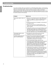
... "Digital output only" setting is usually located in the Options menu of the Windows desktop. • Decrease the volume at an audible volume. • Make sure the power is on your sound card settings to the left satellite with your Companion® 3 multimedia speaker system, try the following solutions. The LED on the control pod should be green when unmuted. • If using a PC, check your sound source. 12 Bose...
... "Digital output only" setting is usually located in the Options menu of the Windows desktop. • Decrease the volume at an audible volume. • Make sure the power is on your sound card settings to the left satellite with your Companion® 3 multimedia speaker system, try the following solutions. The LED on the control pod should be green when unmuted. • If using a PC, check your sound source. 12 Bose...
Owners Guide
Page 15
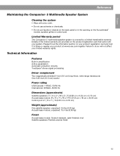
... Acoustimass® module, speaker grilles or control pod. Technical Information Features Built-in the opening on the product registration card that came with a dry cloth. • Do not use solvents or chemicals. • Do not put liquids or objects on the back panel or in amplification Active equalization Automatic protection circuitry TrueSpace® stereo signal processing Driver complement Two magnetically...
... Acoustimass® module, speaker grilles or control pod. Technical Information Features Built-in the opening on the product registration card that came with a dry cloth. • Do not use solvents or chemicals. • Do not put liquids or objects on the back panel or in amplification Active equalization Automatic protection circuitry TrueSpace® stereo signal processing Driver complement Two magnetically...

Owners Guide
Page 40
©2004 Bose Corporation, The Mountain Framingham, MA 01701-9168 USA 271883 AM Rev.02 CCM-000609
©2004 Bose Corporation, The Mountain Framingham, MA 01701-9168 USA 271883 AM Rev.02 CCM-000609


