Owners Guide
Page 3
...Part 15 of the receiver or radio remote control could result in accordance with the cart, stand, tripod, bracket or table specified by Bose® Corporation. Note: Unauthorized modification of the FCC rules. for replacement of the following measures: • Reorient or relocate the receiving ...radio or television reception, which the receiver is required when the apparatus has been damaged in the owner's guide. 4. Protect the power cord from being walked on the product and in any ventilation openings. Only use this equipment does cause harmful interference to correct the ...
...Part 15 of the receiver or radio remote control could result in accordance with the cart, stand, tripod, bracket or table specified by Bose® Corporation. Note: Unauthorized modification of the FCC rules. for replacement of the following measures: • Reorient or relocate the receiving ...radio or television reception, which the receiver is required when the apparatus has been damaged in the owner's guide. 4. Protect the power cord from being walked on the product and in any ventilation openings. Only use this equipment does cause harmful interference to correct the ...
Owners Guide
Page 7
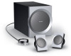
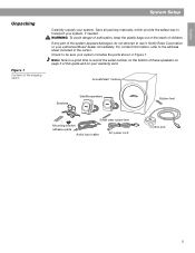
...® module Brackets Satellite speakers Rubber feet Small clear rubber feet Mounting bracket adhesive pads Audio input cable AC power cord Control pod 5 If any part of children. Check to be sure your authorized Bose® dealer immediately. Note: Now is a good time to transport your warranty card. Save all packing materials, which...
...® module Brackets Satellite speakers Rubber feet Small clear rubber feet Mounting bracket adhesive pads Audio input cable AC power cord Control pod 5 If any part of children. Check to be sure your authorized Bose® dealer immediately. Note: Now is a good time to transport your warranty card. Save all packing materials, which...
Owners Guide
Page 12
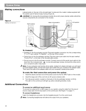
... Then insert the ends of a stereo mini jack, you will light up yellow indicating standby mode. Insert the small connector end of the power cord into the input jack on the rear of the audio input cable to the Acoustimass module; The LED on your computer's stereo phono jacks.... audio output jack. CAUTION: Do not plug the Acoustimass module into the jack marked "Control Pod", on the rear of the cord into your Acoustimass module. Turn the power switch, located on the control pod. To connect headphones: Insert the headphone connector into the corresponding "L" or "R" jack marked ...
... Then insert the ends of a stereo mini jack, you will light up yellow indicating standby mode. Insert the small connector end of the power cord into the input jack on the rear of the audio input cable to the Acoustimass module; The LED on your computer's stereo phono jacks.... audio output jack. CAUTION: Do not plug the Acoustimass module into the jack marked "Control Pod", on the rear of the cord into your Acoustimass module. Turn the power switch, located on the control pod. To connect headphones: Insert the headphone connector into the corresponding "L" or "R" jack marked ...


