

M7TDE user's manual
Page 3
... 1-2 1.1 Features 1-2 1.1.1 Hardware...1-2 1.1.2 BIOS ...1-6 1.1.3 Software...1-6 1.1.4 Accessories ...1-6 1.2 Motherboard Installation 1-7 1.2.1 System Block Diagram 1-7 1.2.2 Layout of Motherboard 1-8 1.2.3 Quick Reference 1-8 1.2.3 Quick Reference 1-9 1.3 CPU Installation 1-10 1.3.1 0CPU Installation Procedure: Socket 478 1-10 1.3.2 CPU Fan Header: JCFAN1 1-11 1.3.3 System Fan Header: JSFAN1 (Optional 1-11 1.4 RAM ...
... 1-2 1.1 Features 1-2 1.1.1 Hardware...1-2 1.1.2 BIOS ...1-6 1.1.3 Software...1-6 1.1.4 Accessories ...1-6 1.2 Motherboard Installation 1-7 1.2.1 System Block Diagram 1-7 1.2.2 Layout of Motherboard 1-8 1.2.3 Quick Reference 1-8 1.2.3 Quick Reference 1-9 1.3 CPU Installation 1-10 1.3.1 0CPU Installation Procedure: Socket 478 1-10 1.3.2 CPU Fan Header: JCFAN1 1-11 1.3.3 System Fan Header: JSFAN1 (Optional 1-11 1.4 RAM ...

M7TDE user's manual
Page 6
...and a game port. 8 Contains on the purchase of your new system! M7TDE Highlights: 8 Contains on board I/O facilities, which brings to you with industry software and hardware standards. This motherboard is designed to provide you the latest technology in data processing. In the tradition... of its predecessors, this motherboard continues the commitment of the latest industry technology to take advantage of...
...and a game port. 8 Contains on the purchase of your new system! M7TDE Highlights: 8 Contains on board I/O facilities, which brings to you with industry software and hardware standards. This motherboard is designed to provide you the latest technology in data processing. In the tradition... of its predecessors, this motherboard continues the commitment of the latest industry technology to take advantage of...
M7TDE user's manual
Page 7
...System Bus interrupt delivery. Supports system bus Dynamic Bus Inversion (DBI). Supports up to 2 GHz CPU core speeds. Chapter 1 Motherboard Description 1. Supports 32-bit system bus addressing. The 66MHz AGP 2.0 compliant interface supports 1x, 2x and 4x data transfer mode....− Intel 82845/82801BA. − Winbond W83627HF. 1-2 The 33MHz 32 bit PCI 2.2 compliant. Speed Runing at 400 MHz Front Side Bus frequency. Motherboard Description 1.1 Features 1.1.1 Hardware CPU − − − − − Single Socket-478 for an Intel Pentium ® 4 processor. ...
...System Bus interrupt delivery. Supports system bus Dynamic Bus Inversion (DBI). Supports up to 2 GHz CPU core speeds. Chapter 1 Motherboard Description 1. Supports 32-bit system bus addressing. The 66MHz AGP 2.0 compliant interface supports 1x, 2x and 4x data transfer mode....− Intel 82845/82801BA. − Winbond W83627HF. 1-2 The 33MHz 32 bit PCI 2.2 compliant. Speed Runing at 400 MHz Front Side Bus frequency. Motherboard Description 1.1 Features 1.1.1 Hardware CPU − − − − − Single Socket-478 for an Intel Pentium ® 4 processor. ...

M7TDE user's manual
Page 8
... down timer from 1 to 15 minutes. − Wakes from power saving sleep mode with a memory controller providing shadow RAM and support for ROM BIOS. Chapter 1 Motherboard Description DRAM Memory − Supports 200MHz or 266MHz DDR SDRAM devices. − Supports 128MB, 256MB, 512MB/ 1GB technologies for x8 and 16 devices. − Supports... one DDR-SDRAM channel, 64 wide (72b with ECC). − No support for DSx16 DIMMs. Shadow RAM − Motherboard is equipped with any keyboard or mouse activity.
... down timer from 1 to 15 minutes. − Wakes from power saving sleep mode with a memory controller providing shadow RAM and support for ROM BIOS. Chapter 1 Motherboard Description DRAM Memory − Supports 200MHz or 266MHz DDR SDRAM devices. − Supports 128MB, 256MB, 512MB/ 1GB technologies for x8 and 16 devices. − Supports... one DDR-SDRAM channel, 64 wide (72b with ECC). − No support for DSx16 DIMMs. Shadow RAM − Motherboard is equipped with any keyboard or mouse activity.

M7TDE user's manual
Page 9
... Onboard − AC-LINK protocol comfliance. − AC'97 2.2compliant. − Energy saving power down modes. − 18-bit full duplex stereo ADC,DACs. Chapter 1 Motherboard Description Built in IDE Facilities − Supports four IDE hard disk drives. − Supports PIO Mode 4, Master Mode, and high performance hard disk drives. −...
... Onboard − AC-LINK protocol comfliance. − AC'97 2.2compliant. − Energy saving power down modes. − 18-bit full duplex stereo ADC,DACs. Chapter 1 Motherboard Description Built in IDE Facilities − Supports four IDE hard disk drives. − Supports PIO Mode 4, Master Mode, and high performance hard disk drives. −...
M7TDE user's manual
Page 10
Chapter 1 Motherboard Description Super I/O Built-in onboard − Support one multi-mode Parallel Port. (1) Standard & Bidirection Parallel Port (SPP). (2) Enhanced Parallel Port (EPP). (3) Extended Capabilities Port (ECP). &#...; Supports 360KB, 720KB, 1.2MB, 1.44MB and 2.88MB floppy disk drives. Accelerated Graphics Port (AGP) Interface − Supports a single AGP device (either a connector or on the motherboard). − Supports AGP 2.0 including 4X AGP data transfers and 2x/4x Fast Write protocol. − Supports only 1.5v AGP electricals. − High priority access support...
Chapter 1 Motherboard Description Super I/O Built-in onboard − Support one multi-mode Parallel Port. (1) Standard & Bidirection Parallel Port (SPP). (2) Enhanced Parallel Port (EPP). (3) Extended Capabilities Port (ECP). &#...; Supports 360KB, 720KB, 1.2MB, 1.44MB and 2.88MB floppy disk drives. Accelerated Graphics Port (AGP) Interface − Supports a single AGP device (either a connector or on the motherboard). − Supports AGP 2.0 including 4X AGP data transfers and 2x/4x Fast Write protocol. − Supports only 1.5v AGP electricals. − High priority access support...
M7TDE user's manual
Page 11
Chapter 1 Motherboard Description 1.1.2 BIOS − AWARD legal BIOS. − Supports APM1.2. − Supports USB Function. − Supports ACPI. 1.1.3 Software Operating System − Offers the highest performance for MS-DOS, Windows NT, Windows 2000, Windows 95/98, Windows ME, Windows XP, LINUX, SCO UNIX etc. 1.1.4 Accessories − HDD Cable. − FDD Cable. − Flash Memory Writer for BIOS Update. − USB Cable (Optional). − Rear I/O Panel for ATX Case (Optional). − Fully Setup Driver CD. 1-6
Chapter 1 Motherboard Description 1.1.2 BIOS − AWARD legal BIOS. − Supports APM1.2. − Supports USB Function. − Supports ACPI. 1.1.3 Software Operating System − Offers the highest performance for MS-DOS, Windows NT, Windows 2000, Windows 95/98, Windows ME, Windows XP, LINUX, SCO UNIX etc. 1.1.4 Accessories − HDD Cable. − FDD Cable. − Flash Memory Writer for BIOS Update. − USB Cable (Optional). − Rear I/O Panel for ATX Case (Optional). − Fully Setup Driver CD. 1-6

M7TDE user's manual
Page 13
Chapter 1 Motherboard Description 1.2.2 Layout of Motherboard Model No.M7TDE K/B & Mouse JKBMS1 JRJ45USB1 JATXPWR2 USB & LAN JCOM1 JPRNT1 Socket 478 JCFAN1 JDIMMVOLT COM1 DDR1 DDR2 Parallel Port COM2 JCOM2 JSPKR1 SP-OUT JGAME1 GAME Port JLIN1 LINE-IN JMIC1 MIC-IN JTAD1 JAUDIO1 LAN CHIP JCDIN1 Intel 82845 AGP1 PCI1 JAUXPWR1 JATXPWR1 PCI2 Intel 82801BA LPC I/O CNR1 PCI3 BAT1 ROM1 JWOL1 JSFAN1 JUSB2 FDD1 IDE2 IDE1 JCMOS1 JPANEL1 1-8
Chapter 1 Motherboard Description 1.2.2 Layout of Motherboard Model No.M7TDE K/B & Mouse JKBMS1 JRJ45USB1 JATXPWR2 USB & LAN JCOM1 JPRNT1 Socket 478 JCFAN1 JDIMMVOLT COM1 DDR1 DDR2 Parallel Port COM2 JCOM2 JSPKR1 SP-OUT JGAME1 GAME Port JLIN1 LINE-IN JMIC1 MIC-IN JTAD1 JAUDIO1 LAN CHIP JCDIN1 Intel 82845 AGP1 PCI1 JAUXPWR1 JATXPWR1 PCI2 Intel 82801BA LPC I/O CNR1 PCI3 BAT1 ROM1 JWOL1 JSFAN1 JUSB2 FDD1 IDE2 IDE1 JCMOS1 JPANEL1 1-8

M7TDE user's manual
Page 14
... Connector (IDE1) U. AGP Slot (AGP1) L. Back Panel I . Front Audio Header (JAUDIO1) N. CNR Slot (CNR1) P. Wake-On-LAN Header (JWOL1) (JDIMMVOLT) G. Front USB Header (JUSB2) S. Chapter 1 Motherboard Description 1.2.3 Quick Reference E DC B A Winbond I/O U LAN CHIP T S Socket 478 F G ROM1 82845 82801BA H I R DIMM1 Q DIMM2 JK L M A. Secondary IDE Connector (IDE2) B. Floppy Disk Connector (FDD1...
... Connector (IDE1) U. AGP Slot (AGP1) L. Back Panel I . Front Audio Header (JAUDIO1) N. CNR Slot (CNR1) P. Wake-On-LAN Header (JWOL1) (JDIMMVOLT) G. Front USB Header (JUSB2) S. Chapter 1 Motherboard Description 1.2.3 Quick Reference E DC B A Winbond I/O U LAN CHIP T S Socket 478 F G ROM1 82845 82801BA H I R DIMM1 Q DIMM2 JK L M A. Secondary IDE Connector (IDE2) B. Floppy Disk Connector (FDD1...
M7TDE user's manual
Page 15
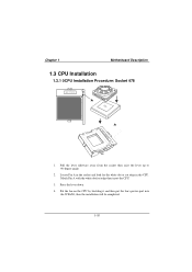
Put the fan on the CPU by buckling it and then put the fan's power-port into the JCFAN1, then the installation will be completed. 1-10 Press the lever down. 4. Chapter 1 Motherboard Description 1.3 CPU Installation 1.3.1 0CPU Installation Procedure: Socket 478 Socket 478 CPU 1. Locate Pin A in the CPU. Match Pin A with the white dot/cut edge in the socket and look for the white dot or cut edge then insert the CPU. 3. Pull the lever sideways away from the socket then raise the lever up to 90-degree angle. 2.
Put the fan on the CPU by buckling it and then put the fan's power-port into the JCFAN1, then the installation will be completed. 1-10 Press the lever down. 4. Chapter 1 Motherboard Description 1.3 CPU Installation 1.3.1 0CPU Installation Procedure: Socket 478 Socket 478 CPU 1. Locate Pin A in the CPU. Match Pin A with the white dot/cut edge in the socket and look for the white dot or cut edge then insert the CPU. 3. Pull the lever sideways away from the socket then raise the lever up to 90-degree angle. 2.

M7TDE user's manual
Page 16
Chapter 1 CPU Installation Layout Socket 478 Motherboard Description 1 JCFAN1 DIMM1 DIMM2 82845 LAN CHIP 82801BA LPC I/O ROM1 1.3.2 CPU Fan Header: JCFAN1 Pin No. 1 2 3 Assignment Ground +12V Sense 1 JSFAN1 1.3.3 System Fan Header: JSFAN1 (Optional) Pin No. 1 2 3 Assignment Ground +12V Sense 1-11
Chapter 1 CPU Installation Layout Socket 478 Motherboard Description 1 JCFAN1 DIMM1 DIMM2 82845 LAN CHIP 82801BA LPC I/O ROM1 1.3.2 CPU Fan Header: JCFAN1 Pin No. 1 2 3 Assignment Ground +12V Sense 1 JSFAN1 1.3.3 System Fan Header: JSFAN1 (Optional) Pin No. 1 2 3 Assignment Ground +12V Sense 1-11
M7TDE user's manual
Page 17
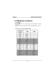
Chapter 1 Motherboard Description 1.4 RAM Module Installation 1.4.1 DIMM DRAM Access Time: 2.5V Unbuffered/ Registered DDR SDRAM PC 200/266 Type required. DRAM Type: 64MB/ 128MB/ 256MB/ 512MB/ 1GB ...
Chapter 1 Motherboard Description 1.4 RAM Module Installation 1.4.1 DIMM DRAM Access Time: 2.5V Unbuffered/ Registered DDR SDRAM PC 200/266 Type required. DRAM Type: 64MB/ 128MB/ 256MB/ 512MB/ 1GB ...

M7TDE user's manual
Page 18
Chapter 1 Motherboard Description Total Memory Size (MB) 576 M 640 M 768 M 1024 M 1.512 G 1.064 G 1.128 G 1.256 G 1.512 G 2 G 1 DIMM 64 M 128 M 256 M 512 M 1G 64 M 128 M 256 M 512 M 1G 2 DMMs 512 M 512 M 512 M 512 M 512 M 1G 1G 1G 1G 1G * The list shown above for DRAM configuration is only for reference. 1-13
Chapter 1 Motherboard Description Total Memory Size (MB) 576 M 640 M 768 M 1024 M 1.512 G 1.064 G 1.128 G 1.256 G 1.512 G 2 G 1 DIMM 64 M 128 M 256 M 512 M 1G 64 M 128 M 256 M 512 M 1G 2 DMMs 512 M 512 M 512 M 512 M 512 M 1G 1G 1G 1G 1G * The list shown above for DRAM configuration is only for reference. 1-13
M7TDE user's manual
Page 19
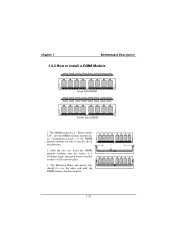
The DIMM socket has a " Plastic Safety Tab", and the DIMM memory module has an "Asymmetrical notch", so the DIMM memory module can only fit into the place. 3. The Mounting Holes and plastic tabs should fit over the edge and hold the DIMM memory modules in one direction. 2. Push the tabs out. Insert the DIMM memory modules into the socket at a 90-degree angle, then push down vertically so that it will fit into the slot in place. 1-14 Chapter 1 Motherboard Description 1.4.2 How to install a DIMM Module Single Sided DIMM Double Sided DIMM 1.
The DIMM socket has a " Plastic Safety Tab", and the DIMM memory module has an "Asymmetrical notch", so the DIMM memory module can only fit into the place. 3. The Mounting Holes and plastic tabs should fit over the edge and hold the DIMM memory modules in one direction. 2. Push the tabs out. Insert the DIMM memory modules into the socket at a 90-degree angle, then push down vertically so that it will fit into the slot in place. 1-14 Chapter 1 Motherboard Description 1.4.2 How to install a DIMM Module Single Sided DIMM Double Sided DIMM 1.
M7TDE user's manual
Page 20
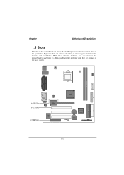
Chapter 1 Motherboard Description 1.5 Slots The slots in this motherboard are not part of adding or enhancing the motherboard's features and capabilities. With these efficient facilities, you can increase the motherboard's capabilities by adding hardware that performs tasks that are designed to hold expansion cards and connect them to the system bus. Socket 478 DIMM1 DIMM2 AGP Slot PCI Slots CNR Slot LAN CHIP LPC I/O 82845 82801BA ROM1 1-15 Expansion slots are a means of the basic system.
Chapter 1 Motherboard Description 1.5 Slots The slots in this motherboard are not part of adding or enhancing the motherboard's features and capabilities. With these efficient facilities, you can increase the motherboard's capabilities by adding hardware that performs tasks that are designed to hold expansion cards and connect them to the system bus. Socket 478 DIMM1 DIMM2 AGP Slot PCI Slots CNR Slot LAN CHIP LPC I/O 82845 82801BA ROM1 1-15 Expansion slots are a means of the basic system.

M7TDE user's manual
Page 21
... will take advantage of AGP technology for one of the expansion slots. Chapter 1 Motherboard Description 1.5.1 AGP (Accelerated Graphics Port) Slot Unlike the mouse ports, keyboard ports and printer ports, this motherboard does not have built in most ports. This motherboard supports video cards for PCI slots, but it is a bus standard for expansion... open Industry Standard Architecture, and it defines a hardware scalable riser card interface, which supports audio, network and modem only. 1.5.3 PCI (Peripheral Component Interconnect) Slots This motherboard is designated as 32 bits. 1-16
... will take advantage of AGP technology for one of the expansion slots. Chapter 1 Motherboard Description 1.5.1 AGP (Accelerated Graphics Port) Slot Unlike the mouse ports, keyboard ports and printer ports, this motherboard does not have built in most ports. This motherboard supports video cards for PCI slots, but it is a bus standard for expansion... open Industry Standard Architecture, and it defines a hardware scalable riser card interface, which supports audio, network and modem only. 1.5.3 PCI (Peripheral Component Interconnect) Slots This motherboard is designated as 32 bits. 1-16

M7TDE user's manual
Page 22
Chapter 1 Motherboard Description 1.6 Connectors, Headers & Jumpers The connectors, headers and jumpers introduced below provide you to select a different system options. Socket 478 JATXPWR2 JDIMMVOLT DIMM1 DIMM2 JAUXPWR1 LAN CHIP LPC I/O 82845 82801BA JATXPWR1 IDE2 IDE1 FDD1 JWOL1 ROM1 JCMOS1 JPANEL1 JUSB2 1-17 Noticeably, a jumper has two or more pins covered by a plastic jumper cap, allowing you lots of capabilities such as power supply, front panel signal revelation, IDE hard disk connection, floppy disk connection, Wake On LAN function and Front USB connection.
Chapter 1 Motherboard Description 1.6 Connectors, Headers & Jumpers The connectors, headers and jumpers introduced below provide you to select a different system options. Socket 478 JATXPWR2 JDIMMVOLT DIMM1 DIMM2 JAUXPWR1 LAN CHIP LPC I/O 82845 82801BA JATXPWR1 IDE2 IDE1 FDD1 JWOL1 ROM1 JCMOS1 JPANEL1 JUSB2 1-17 Noticeably, a jumper has two or more pins covered by a plastic jumper cap, allowing you lots of capabilities such as power supply, front panel signal revelation, IDE hard disk connection, floppy disk connection, Wake On LAN function and Front USB connection.

M7TDE user's manual
Page 23
The speaker is not connected to the motherboard at the front panel connector. Chapter 1 Motherboard Description 1.6.1 Front Panel Connector: JPANEL1 K SLP NA P-LED PWR E (+) (+) (-) Y IrDA 2 24 1 23 SPEK (+) (-) HDLED REST NA IrDA Pin Assignment No. 1 Speaker 3 NC 5 ... KEY 22 Ground 24 IRRX Function Sleep Button POWER LED POWER Button IrDA Connector Speaker Connector An offboard speaker can be installed on the motherboard as a manufacturing option. It can be connected to the audio subsystem and does not receive output from the audio subsystem. 1-18 The...
The speaker is not connected to the motherboard at the front panel connector. Chapter 1 Motherboard Description 1.6.1 Front Panel Connector: JPANEL1 K SLP NA P-LED PWR E (+) (+) (-) Y IrDA 2 24 1 23 SPEK (+) (-) HDLED REST NA IrDA Pin Assignment No. 1 Speaker 3 NC 5 ... KEY 22 Ground 24 IRRX Function Sleep Button POWER LED POWER Button IrDA Connector Speaker Connector An offboard speaker can be installed on the motherboard as a manufacturing option. It can be connected to the audio subsystem and does not receive output from the audio subsystem. 1-18 The...

M7TDE user's manual
Page 24
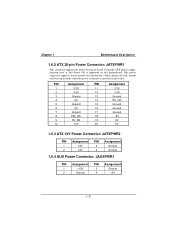
... button will illuminate while the computer is not in the system BIOS, and the APM driver must pass before the power supply will cause the motherboard to reset and run the POST (Power On Self Test). The LED will power down the monitor and the hard disk when is powered on... where it will recognize another on/off . (The time required is applied only applies to those IDE drives directly attached to the system board. Chapter 1 Motherboard Description Reset Button This connector can be attached to an LED on the front panel of a computer case.
... button will illuminate while the computer is not in the system BIOS, and the APM driver must pass before the power supply will cause the motherboard to reset and run the POST (Power On Self Test). The LED will power down the monitor and the hard disk when is powered on... where it will recognize another on/off . (The time required is applied only applies to those IDE drives directly attached to the system board. Chapter 1 Motherboard Description Reset Button This connector can be attached to an LED on the front panel of a computer case.
M7TDE user's manual
Page 25
... functionality, which means that the system will boot up instantly when the power connector is supported on this motherboard. Using the ATX power supply, function such as Soft Power Off is inserted on -board. Chapter 1 Motherboard Description 1.6.2 ATX 20-pin Power Connector: JATXPWR1 This connector supports the power button on the board.
... functionality, which means that the system will boot up instantly when the power connector is supported on this motherboard. Using the ATX power supply, function such as Soft Power Off is inserted on -board. Chapter 1 Motherboard Description 1.6.2 ATX 20-pin Power Connector: JATXPWR1 This connector supports the power button on the board.

