

User Guide
Page 1
... of a Class B digital device, pursuant to Part 15 of this publication and to make changes to the contents here without first obtaining the vendor's approval in a particular installation. The content of merchantability or...user's manual. Duplication of the FCC Rules. K8T80-A7 FCC Information and Copyright This equipment has been tested and found in a residential installation. There is not allowed without obligation to notify any party beforehand. This equipment generates, uses and can radiate radio frequency energy and, if not installed and used in accordance with the instructions...
... of a Class B digital device, pursuant to Part 15 of this publication and to make changes to the contents here without first obtaining the vendor's approval in a particular installation. The content of merchantability or...user's manual. Duplication of the FCC Rules. K8T80-A7 FCC Information and Copyright This equipment has been tested and found in a residential installation. There is not allowed without obligation to notify any party beforehand. This equipment generates, uses and can radiate radio frequency energy and, if not installed and used in accordance with the instructions...

User Guide
Page 2
... 1.3 1.4 Introduction 1 Features 1 Package List 3 Layout 4 Components 5 Chapter 2: 2.1 2.2 2.3 2.4 Hardware Installation 6 Central Processing Unit (CPU 6 FAN Headers 8 Memory Module Installation 8 Connectors and Slots 9 Chapter 3: 3.1 3.2 Headers & Jumpers Setup 10 How to Setup Jumpers 10 Detail Settings 10 Chapter 4: 4.1 4.2 4.3 Useful Help 14 Award BIOS Beep Code 14 Extra Information 14 Troubleshooting 16 Chapter 5: 5.1 5.2 5.3 5.4 WarpSpeeder 17 Introduction 17 System Requirement 17 Installation 18 [WarpSpeeder™] includes 1 tray icon and 5 panels 19 ii
... 1.3 1.4 Introduction 1 Features 1 Package List 3 Layout 4 Components 5 Chapter 2: 2.1 2.2 2.3 2.4 Hardware Installation 6 Central Processing Unit (CPU 6 FAN Headers 8 Memory Module Installation 8 Connectors and Slots 9 Chapter 3: 3.1 3.2 Headers & Jumpers Setup 10 How to Setup Jumpers 10 Detail Settings 10 Chapter 4: 4.1 4.2 4.3 Useful Help 14 Award BIOS Beep Code 14 Extra Information 14 Troubleshooting 16 Chapter 5: 5.1 5.2 5.3 5.4 WarpSpeeder 17 Introduction 17 System Requirement 17 Installation 18 [WarpSpeeder™] includes 1 tray icon and 5 panels 19 ii

User Guide
Page 3
.... Integrate hardware monitor functions. 10/100 LAN Chip: Realtek RTL8100C. Supports ACPI, PCI power management. 1 Supports 200/400/600/800 clock rates with Double Data Rate style operation for 400/800/1200/1600MT/s in both directions simultaneously for reference.) DIMM Socket Location DDR Module Total Memory Size DIMM1 DIMM2 128MB/256MB/512MB/1GB *1 128MB/256MB/512MB/1GB *1 Max is up to 2 DDR devices. K8T80-A7 CHAPTER 1: INTRODUCTION...
.... Integrate hardware monitor functions. 10/100 LAN Chip: Realtek RTL8100C. Supports ACPI, PCI power management. 1 Supports 200/400/600/800 clock rates with Double Data Rate style operation for 400/800/1200/1600MT/s in both directions simultaneously for reference.) DIMM Socket Location DDR Module Total Memory Size DIMM1 DIMM2 128MB/256MB/512MB/1GB *1 128MB/256MB/512MB/1GB *1 Max is up to 2 DDR devices. K8T80-A7 CHAPTER 1: INTRODUCTION...

User Guide
Page 4
...Onboard AC'97 Sound Codec Chip: ALC655 Support 6 channels. Internal On-board I/O Connectors and Headers 1 front panel header supports front panel facilities. 1 CD-in connector supports 1 CD-ROM audio-in SB VT8237R. K8T80-A7 Slot 5 x PCI bus master slots. 1 x AGP 4x/8x compatible slot. 1 x CNR slot. Supports PIO mode 5, Bus Master, and Ultra DMA 33/66/100/133 function. Data transfer rates up to 150 MB/s. - Complaints with 360K, 720K, 1.2M, 1.44M and 2.88Mbytes. 2 IDE connectors support 4 hard disk devices. 2 serial ATA connectors support 2 SATA devices. 2 USB headers support 4 USB 2.0 ports...
...Onboard AC'97 Sound Codec Chip: ALC655 Support 6 channels. Internal On-board I/O Connectors and Headers 1 front panel header supports front panel facilities. 1 CD-in connector supports 1 CD-ROM audio-in SB VT8237R. K8T80-A7 Slot 5 x PCI bus master slots. 1 x AGP 4x/8x compatible slot. 1 x CNR slot. Supports PIO mode 5, Bus Master, and Ultra DMA 33/66/100/133 function. Data transfer rates up to 150 MB/s. - Complaints with 360K, 720K, 1.2M, 1.44M and 2.88Mbytes. 2 IDE connectors support 4 hard disk devices. 2 serial ATA connectors support 2 SATA devices. 2 USB headers support 4 USB 2.0 ports...

User Guide
Page 5
... performance for ATX case x1 USB 2.0 cable x1 (optional) Serial ATA cable x2 (optional) S/PDIF out cable x1 (optional) 3 K8T80-A7 Back Panel I /O panel for Windows 98SE, Windows NT, Windows 2000, Windows ME, Windows XP, Linux Fedora, and UNIX series. 1.2 PACKAGE LIST FDD cable x1 HDD cable x1 User's Manual x1 Fully Setup Driver CD x1 Rear I /O Connectors 4 USB 2.0 ports. 1 serial port. 1 parallel port. 1 RJ-45 LAN jack. 1 PS/2 Mouse & Keyboard port. 1 vertical audio port including 1 line-in connector, 1 Line out connector, and 1 MIC in connector. BIOS & Software BIOS Award legal BIOS. PS...
... performance for ATX case x1 USB 2.0 cable x1 (optional) Serial ATA cable x2 (optional) S/PDIF out cable x1 (optional) 3 K8T80-A7 Back Panel I /O panel for Windows 98SE, Windows NT, Windows 2000, Windows ME, Windows XP, Linux Fedora, and UNIX series. 1.2 PACKAGE LIST FDD cable x1 HDD cable x1 User's Manual x1 Fully Setup Driver CD x1 Rear I /O Connectors 4 USB 2.0 ports. 1 serial port. 1 parallel port. 1 RJ-45 LAN jack. 1 PS/2 Mouse & Keyboard port. 1 vertical audio port including 1 line-in connector, 1 Line out connector, and 1 MIC in connector. BIOS & Software BIOS Award legal BIOS. PS...
User Guide
Page 6
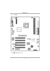
CPU1 IDE2 IDE1 2 JUSB4 1 10 2 10 JUSB3 1 1 JUSBV2 VT8237R Super I/O JSATA2 7 1 JSATA1 7 1 JCMOS1 JCI1 1 1 BAT1 JSFAN1 1 BIOS JPANEL1 2 24 1 23 4 1.3 LAYOUT JKBMS1 JKBV1 1 JATXPWR2 JATXPWR1 K8T80-A7 JCFAN1 1 JCOM2 DIMM1 DIMM2 FDD1 JPRNT1 JUSBV1 1 JUSB1 JUSBLAN1 K8T800 Pro JAUDIO1 AGP1 PCI1 LAN PCI2 JAUDIO2 2 14 1 13 1 JCDIN1 1 JSPDIF_OUT1 Codec CNR1 PCI3 PCI4 PCI5 Note: ■ represents the 1st pin.
CPU1 IDE2 IDE1 2 JUSB4 1 10 2 10 JUSB3 1 1 JUSBV2 VT8237R Super I/O JSATA2 7 1 JSATA1 7 1 JCMOS1 JCI1 1 1 BAT1 JSFAN1 1 BIOS JPANEL1 2 24 1 23 4 1.3 LAYOUT JKBMS1 JKBV1 1 JATXPWR2 JATXPWR1 K8T80-A7 JCFAN1 1 JCOM2 DIMM1 DIMM2 FDD1 JPRNT1 JUSBV1 1 JUSB1 JUSBLAN1 K8T800 Pro JAUDIO1 AGP1 PCI1 LAN PCI2 JAUDIO2 2 14 1 13 1 JCDIN1 1 JSPDIF_OUT1 Codec CNR1 PCI3 PCI4 PCI5 Note: ■ represents the 1st pin.

User Guide
Page 7
...: Digital audio-out connector. D. AGP1: Accelerated Graphics Port slot. JUSB3/JUSB4: Front panel USB ports Interconnect slots. H. S. DIMM1/DIMM2: DDR memory modules. K. K8T80-A7 1.4 COMPONENTS H I GF ED C B Codec LAN A J K8T800 Pro CPU1 BAT1 BIOS Super I . header. Rear side connectors (back panel). N. JSATA1/JSATA2: Serial ATA device connectors. JUSBV2: Power source header for USB ports at back panel. I /O VT8237R K L MN O PQ R S T U A. JCFAN1: CPU fan power source slot. JATXPWR1/JATXPWR2: ATX power L. FDD1: Floppy disk connector...
...: Digital audio-out connector. D. AGP1: Accelerated Graphics Port slot. JUSB3/JUSB4: Front panel USB ports Interconnect slots. H. S. DIMM1/DIMM2: DDR memory modules. K. K8T80-A7 1.4 COMPONENTS H I GF ED C B Codec LAN A J K8T800 Pro CPU1 BAT1 BIOS Super I . header. Rear side connectors (back panel). N. JSATA1/JSATA2: Serial ATA device connectors. JUSBV2: Power source header for USB ports at back panel. I /O VT8237R K L MN O PQ R S T U A. JCFAN1: CPU fan power source slot. JATXPWR1/JATXPWR2: ATX power L. FDD1: Floppy disk connector...

User Guide
Page 9
This completes the installation. 7 K8T80-A7 Step 3: Hold the CPU down firmly, and then close the lever to the JCFAN1. Connect the CPU FAN power cable to complete the installation. Step 4: Put the CPU Fan on the CPU and buckle it.
This completes the installation. 7 K8T80-A7 Step 3: Hold the CPU down firmly, and then close the lever to the JCFAN1. Connect the CPU FAN power cable to complete the installation. Step 4: Put the CPU Fan on the CPU and buckle it.

User Guide
Page 10
... slot such that the red wire is the positive and should be connected to GND. 2.3 1. The fan wiring and plug may be different according to pin#1. K8T80-A7 2.2 FAN HEADERS These fan headers support cooling-fans built in place and the DIMM is Ground and should be connected to pin#2, and the black wire is properly seated. 8 Connect the fan cable to the connector while matching the black wire to the fan manufacturer. CPU FAN Header: JCFAN1 Pin...
... slot such that the red wire is the positive and should be connected to GND. 2.3 1. The fan wiring and plug may be different according to pin#1. K8T80-A7 2.2 FAN HEADERS These fan headers support cooling-fans built in place and the DIMM is Ground and should be connected to pin#2, and the black wire is properly seated. 8 Connect the fan cable to the connector while matching the black wire to the fan manufacturer. CPU FAN Header: JCFAN1 Pin...

User Guide
Page 11
... Network Riser Slot The CNR specification is an open Industry Standard Architecture, and it is designated as 32 bits. IDE1/IDE2: Hard Disk Connectors The motherboard has a 32-bit Enhanced PCI IDE Controller that video card. The IDE connectors can connect a master and a slave drive, so you can connect up to IDE1. Pin Assignment Pin Assignment 1 Ground 7 1 3 TX- This connector supports the provided floppy drive ribbon cables. JSATA1~2 5 RX- 2 TX+ 4 Ground 6 RX+ 7 Ground 9 This motherboard supports video cards for expansion cards. K8T80-A7 2.4 CONNECTORS...
... Network Riser Slot The CNR specification is an open Industry Standard Architecture, and it is designated as 32 bits. IDE1/IDE2: Hard Disk Connectors The motherboard has a 32-bit Enhanced PCI IDE Controller that video card. The IDE connectors can connect a master and a slave drive, so you can connect up to IDE1. Pin Assignment Pin Assignment 1 Ground 7 1 3 TX- This connector supports the provided floppy drive ribbon cables. JSATA1~2 5 RX- 2 TX+ 4 Ground 6 RX+ 7 Ground 9 This motherboard supports video cards for expansion cards. K8T80-A7 2.4 CONNECTORS...

User Guide
Page 12
... 4 Ground 10 When the jumper cap is placed on the ATX power supply. Pin opened Pin closed Pin1-2 closed 3.2 DETAIL SETTINGS JATXPWR1/PATXPWR2: ATX Power Source Connectors JATXPWR1: This connector allows user to CPU power circuit. JATXPWR2: By connecting this connector, it will provide +12V to connect with 20-pin power connector on pins, the jumper is "close", if not, that means the jumper is "open". K8T80-A7 CHAPTER 3: HEADERS & JUMPERS SETUP 3.1 HOW TO SETUP JUMPERS The illustration shows how...
... 4 Ground 10 When the jumper cap is placed on the ATX power supply. Pin opened Pin closed Pin1-2 closed 3.2 DETAIL SETTINGS JATXPWR1/PATXPWR2: ATX Power Source Connectors JATXPWR1: This connector allows user to CPU power circuit. JATXPWR2: By connecting this connector, it will provide +12V to connect with 20-pin power connector on pins, the jumper is "close", if not, that means the jumper is "open". K8T80-A7 CHAPTER 3: HEADERS & JUMPERS SETUP 3.1 HOW TO SETUP JUMPERS The illustration shows how...
User Guide
Page 13
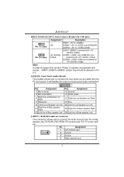
... connect the front audio out put cable with the PC front panel. JUSBV2: JUSB3/JUSB4 are powered with +5V standby voltage. JAUDIO2: Front Panel Audio Header This header allows user to connect the audio source from the veriaty devices, like CD-ROM, DVD-ROM, PCI sound card, PCI TV turner card etc.. JUSBV2: +5V for JUSB1 and JUSBLAN1. Pin Assignment 1 Left channel input 1 2 Ground 3 Ground 4 Right channel input 11 K8T80-A7 JKBV1/JUSBV1/JUSBV2: Power Source Headers for USB ports 1 Pin 1-2 close 1 Pin...
... connect the front audio out put cable with the PC front panel. JUSBV2: JUSB3/JUSB4 are powered with +5V standby voltage. JAUDIO2: Front Panel Audio Header This header allows user to connect the audio source from the veriaty devices, like CD-ROM, DVD-ROM, PCI sound card, PCI TV turner card etc.. JUSBV2: +5V for JUSB1 and JUSBLAN1. Pin Assignment 1 Left channel input 1 2 Ground 3 Ground 4 Right channel input 11 K8T80-A7 JKBV1/JUSBV1/JUSBV2: Power Source Headers for USB ports 1 Pin 1-2 close 1 Pin...
User Guide
Page 14
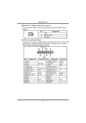
...the PCI bracket SPDIF output header. K8T80-A7 JSPDIF_OUT1: Digital Audio-out Connector This connector allows user to connect the PC case's front panel switch functions. PWR_LED SLP On/Off IR ++ - 2 24 1 +- 23 Pin Assignment SPK RST HLED Function Pin IR Assignment Function 1 +5V 3 N/A 5 N/A Speaker Connector 2 Sleep control 4 Ground 6 N/A Sleep button N/A 7 Speaker 8 Power LED (+) 9 HDD LED (+) 11 HEE LED (-) Hard drive 10 Power LED (+) LED 12 Power LED (-) Power LED 13 Ground 15 Reset control Reset button 14 Power button 16 Ground Power-on , Reset, HDD LED...
...the PCI bracket SPDIF output header. K8T80-A7 JSPDIF_OUT1: Digital Audio-out Connector This connector allows user to connect the PC case's front panel switch functions. PWR_LED SLP On/Off IR ++ - 2 24 1 +- 23 Pin Assignment SPK RST HLED Function Pin IR Assignment Function 1 +5V 3 N/A 5 N/A Speaker Connector 2 Sleep control 4 Ground 6 N/A Sleep button N/A 7 Speaker 8 Power LED (+) 9 HDD LED (+) 11 HEE LED (-) Hard drive 10 Power LED (+) LED 12 Power LED (-) Power LED 13 Ground 15 Reset control Reset button 14 Power button 16 Ground Power-on , Reset, HDD LED...

User Guide
Page 15
... to monitor PC case open signal 2 Ground 13 JCI1: Chassis Open Header This connector allows system to the CMOS and show the message on next boot-up. Remove AC power line. 2. If the signal has been triggered, it allows user to restore the BIOS safe setting and the CMOS data, please carefully follow the procedures to avoid damaging the motherboard. Pin Assignment 1 Case open status. Set the jumper to "Pin...
... to monitor PC case open signal 2 Ground 13 JCI1: Chassis Open Header This connector allows system to the CMOS and show the message on next boot-up. Remove AC power line. 2. If the signal has been triggered, it allows user to restore the BIOS safe setting and the CMOS data, please carefully follow the procedures to avoid damaging the motherboard. Pin Assignment 1 Case open status. Set the jumper to "Pin...

User Guide
Page 16
... respectively BIOS into floppy drive and press Enter. 6. BIOS Update After you fail to DOS prompt. 7. In this Case, please follow the procedure below to restore BIOS. Download the Flash Utility "AWDFLASH.exe" from Biostar website. 4. The BIOS has been recovered and will help to restore the BIOS: 1. Make a bootable floppy disk. 2. Insert the bootable disk into floppy disk. 5. K8T80-A7 CHAPTER 4: USEFUL HELP 4.1 AWARD BIOS BEEP CODE Beep Sound One long beep followed by virus, the Boot-Block function will work...
... respectively BIOS into floppy drive and press Enter. 6. BIOS Update After you fail to DOS prompt. 7. In this Case, please follow the procedure below to restore BIOS. Download the Flash Utility "AWDFLASH.exe" from Biostar website. 4. The BIOS has been recovered and will help to restore the BIOS: 1. Make a bootable floppy disk. 2. Insert the bootable disk into floppy disk. 5. K8T80-A7 CHAPTER 4: USEFUL HELP 4.1 AWARD BIOS BEEP CODE Beep Sound One long beep followed by virus, the Boot-Block function will work...

User Guide
Page 17
... the system shutdown automatically after power on the system again. 15 CPU fan speed is placed evenly with the CPU speed. Remove the power cord from power supply for seconds. 3. Clear the CMOS data. (See "Close CMOS Header: JCMOS1" section) 2. After confirmed, please follow steps below to avoid a damage of the CPU, and the system may not power on again. In this case, please double check: 1. Wait...
... the system shutdown automatically after power on the system again. 15 CPU fan speed is placed evenly with the CPU speed. Remove the power cord from power supply for seconds. 3. Clear the CMOS data. (See "Close CMOS Header: JCMOS1" section) 2. After confirmed, please follow steps below to avoid a damage of the CPU, and the system may not power on again. In this case, please double check: 1. Wait...

User Guide
Page 18
... cable running from hard disk 1. Backing up data and applications files. Make sure power cable is extremely important. check the drive type in . Cannot boot system after installing second hard drive. 1. Using even pressure on . Indicator light on . 3. Set master/slave jumpers correctly. 2. Back up the hard drive is Power light don't illuminate, fan securely plugged in the standard CMOS setup. Review system's equipment. Run SETUP program and select correct drive types. System only boots from optical drive. 1. No power to disk controller board...
... cable running from hard disk 1. Backing up data and applications files. Make sure power cable is extremely important. check the drive type in . Cannot boot system after installing second hard drive. 1. Using even pressure on . Indicator light on . 3. Set master/slave jumpers correctly. 2. Back up the hard drive is Power light don't illuminate, fan securely plugged in the standard CMOS setup. Review system's equipment. Run SETUP program and select correct drive types. System only boots from optical drive. 1. No power to disk controller board...

User Guide
Page 19
The cool Hardware Monitor smartly indicates the temperatures, voltage and CPU fan speed as well as the chipset information. Moreover, to protect users' computer systems if the setting is not appropriate when testing and results in the About panel, you do not need to install DirectX 8.1.) 17 K8T80-A7 CHAPTER 5: WARPSPEEDER™ 5.1 INTRODUCTION [WarpSpeeder™], a new powerful control utility, features three user-friendly functions including Overclock Manager, Overvoltage Manager, and...
The cool Hardware Monitor smartly indicates the temperatures, voltage and CPU fan speed as well as the chipset information. Moreover, to protect users' computer systems if the setting is not appropriate when testing and results in the About panel, you do not need to install DirectX 8.1.) 17 K8T80-A7 CHAPTER 5: WARPSPEEDER™ 5.1 INTRODUCTION [WarpSpeeder™], a new powerful control utility, features three user-friendly functions including Overclock Manager, Overvoltage Manager, and...

User Guide
Page 20
... and immediately launched after you see the following dialog will change according to install. 2. When you click "Finish" button. If the "Launch the WarpSpeeder Tray Utility" checkbox is completed. INSTALLATION Execute the setup execution file, and then the following dialog in this user manual will pop up. Please click "Next" button and follow the default procedure to your motherboard on hand. 18
... and immediately launched after you see the following dialog will change according to install. 2. When you click "Finish" button. If the "Launch the WarpSpeeder Tray Utility" checkbox is completed. INSTALLATION Execute the setup execution file, and then the following dialog in this user manual will pop up. Please click "Next" button and follow the default procedure to your motherboard on hand. 18

User Guide
Page 25
...;] utility will restore to the hardware default setting or load the verified best and stable frequency according to the Recovery Dialog's setting. If the testing fail, system will be saved into system registry. "Auto-overclock button": User can get the real-time status information of testing until system fail. If the testing is required. And please make sure your system. K8T80-A7 c. Hardware Monitor Panel...
...;] utility will restore to the hardware default setting or load the verified best and stable frequency according to the Recovery Dialog's setting. If the testing fail, system will be saved into system registry. "Auto-overclock button": User can get the real-time status information of testing until system fail. If the testing is required. And please make sure your system. K8T80-A7 c. Hardware Monitor Panel...


