Biostar K8M80-M7A Support and Manuals
Get Help and Manuals for this Biostar item

View All Support Options Below
Free Biostar K8M80-M7A manuals!
Problems with Biostar K8M80-M7A?
Ask a Question
Free Biostar K8M80-M7A manuals!
Problems with Biostar K8M80-M7A?
Ask a Question
Popular Biostar K8M80-M7A Manual Pages
K8M800-M7A user's manual - Page 2
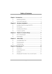
... Central Processing Unit (CPU 5
2.2
FAN Headers 6
2.3
Installing System Memory 7
2.4
Connectors and Slots 8
Chapter 3: Headers & Jumpers Setup 11
3.1
How to Setup Jumpers 11
3.2
Detail Settings 11
Chapter 4: Useful Help 17
4.1
Award BIOS Beep Code 17
4.2
Extra Information 17
4.3
Troubleshooting 19
Chapter 5: WarpSpeeder 20
5.1
Introduction 20
5.2
System...
K8M800-M7A user's manual - Page 3
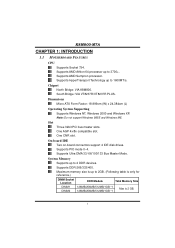
... up to 1600MT/s. Slot Three 32bit PCI bus master slots.
K8M800-M7A
CHAPTER 1: INTRODUCTION
1.1 MOTHERBOARD FEATURES
CPU Supports Socket 754. On-board IDE Two on-board connectors support 4 IDE disk drives. Chipset North Bridge: VIA K8M800. Supports AMD Athlon 64 processor up to 3700+. Supports PIO mode 0~4. System Memory Supports up to 2 DDR devices. One AGP 4x/8x compatible...
K8M800-M7A user's manual - Page 5
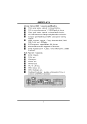
... Port Speaker Out Line In Mic In
3 K8M800-M7A
Internal On-board I/O Connectors and Headers 1 front panel header supports front panel facilities. 1 CD-in connector supports 1 CD-ROM audio-in device. 1 front audio header supports front panel audio function. 1 S/PDIF-Out connector supports digital audio-out function. 1 chassis open header supports PC case-opened warning function. 1 FDD connector...
K8M800-M7A user's manual - Page 8
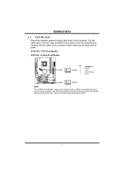
.... JCFAN1: CPU Fan Header
JSFAN1: System Fan Header
13
Pin Assignment
1
Ground
JCFAN1 2 +12V
3
FAN RPM rate
sense
13
JSFAN1
Note:
The JCFAN1 and JSFAN1 support 3-pin head connector.
The fan cable and connector may be connected to pin#1. K8M800-M7A
2.2 FAN HEADERS
These fan headers support cooling-fans built in the computer.
K8M800-M7A user's manual - Page 9
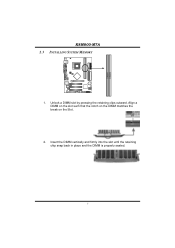
Align a DIMM on the slot such that the notch on the DIMM matches the break on the Slot.
2. DIMM1 DIMM2
K8M800-M7A 2.3 INSTALLING SYSTEM MEMORY
1. Insert the DIMM vertically and firmly into the slot until the retaining chip snap back in place and the DIMM is properly seated.
7 Unlock a DIMM slot by pressing the retaining clips outward.
K8M800-M7A user's manual - Page 10
...connect up to IDE1.
40
39
2
IDE1
1
IDE2
8
K8M800-M7A
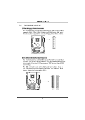
2.4 CONNECTORS AND SLOTS
FDD1: Floppy Disk Connector The motherboard provides a standard floppy disk connector that provides PIO Mode 0~4, ... This connector supports the provided floppy drive ribbon cables.
34
33
2
1
IDE1/IDE2: Hard Disk Connectors
The motherboard has a 32-bit Enhanced PCI IDE Controller that supports 360K, 720K...
K8M800-M7A user's manual - Page 11
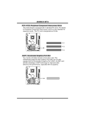
...Peripheral Component Interconnect, and it is also equipped with 3 standard PCI slots. K8M800-M7A
PCI1~PCI3: Peripheral Component Interconnect Slots This motherboard is equipped with an Accelerated Graphics Port (AGP).
PCI1 PCI2 PCI3
AGP1: Accelerated... and performance, especially with 3D graphics.
9 This motherboard supports video cards for PCI slots, but it is designated as 32 bits.
K8M800-M7A user's manual - Page 12
K8M800-M7A
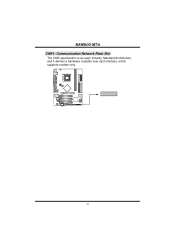
CNR1: Communication Network Riser Slot The CNR specification is an open Industry Standard Architecture, and it defines a hardware scalable riser card interface, which supports modem only.
10
K8M800-M7A user's manual - Page 13
...SLP
On/Off
++ 2
1
+- When the jumper cap is "open". It allows user to set up jumpers. SPK
RST
HLED
IR
24 23 IR
Pin
Assignment
1 +5V
3 N/A
5 N/A...
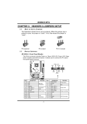
3.2 DETAIL SETTINGS
JPANEL1: Front Panel Header
This 24-pin connector includes Power-on, Reset, HDD LED, Power LED, Sleep button, speaker and IrDA Connection. K8M800-M7A
CHAPTER 3: HEADERS & JUMPERS SETUP
3.1 HOW TO SETUP JUMPERS
The ...
K8M800-M7A user's manual - Page 17
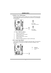
Reset your desired password or clear the CMOS data. K8M800-M7A
JCMOS1: Clear CMOS Header
By placing the jumper on the AC. 6. Set the jumper to "Pin 2-3 close ". 5. Power on pin2-3, it will record to avoid damaging the motherboard.
1 3
Pin 1-2 Close: Normal Operation (default).
1
1
3
3
Pin 2-3 Close:
Clear CMOS data.
※ Clear CMOS Procedures:
1. If the signal...
K8M800-M7A user's manual - Page 19
... POST No DRAM detected or install
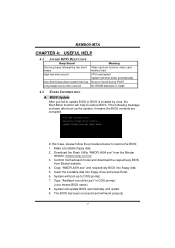
4.2 EXTRA INFORMATION
A. Download the Flash Utility "AWDFLASH.exe" from Biostar website. 4. System will shut down automatically No error found or video card memory bad CPU overheated System will boot-up the system, it means the BIOS contents are corrupted. The BIOS has been recovered and will update BIOS automatically and restart. 9. Copy...
K8M800-M7A user's manual - Page 21
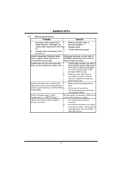
...equipment. System inoperative.
Set master/slave jumpers correctly.
2. Replace cable. drive, can be booted from hard disk 2. check the drive type in setup. System only boots ... but booting from optical drive.
2. Cannot boot system after installing second hard drive.
1. K8M800-M7A
4.3 TROUBLESHOOTING
Probable
Solution
1. No power to disk controller board. Make ...
K8M800-M7A user's manual - Page 22
...systems if the setting is not ...then restart to install DirectX 8.1.)
20 In addition, the frequency status of CPU, memory, AGP and PCI along with just one .
5.2 SYSTEM REQUIREMENT
OS Support: Windows 98 .... If you use Windows XP, you can get detail descriptions about BIOS model and chipsets. K8M800-M7A
CHAPTER 5: WARPSPEEDER™
5.1 INTRODUCTION
[WarpSpeeder™], a new powerful...
K8M800-M7A user's manual - Page 23
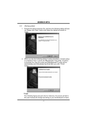
... the default procedure to your motherboard on hand.
21 Execute the setup execution file, and then the following figures are just only for reference, the screen printed in setup procedure, it means setup is checked, the Tray Icon utility and [WarpSpeeder™] utility will be automatically and immediately launched after you click "Finish" button.
K8M800-M7A 5.3 INSTALLATION
1.
K8M800-M7A user's manual - Page 26
K8M800-M7A
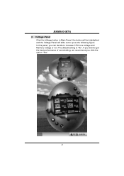
3. The default setting is "No". If you click the option "Yes".
24 In this panel, you can decide to get the best performance of overclocking, we recommend you want to increase CPU core voltage and Memory voltage or not. Voltage Panel Click the Voltage button in Main Panel, the button will be highlighted and the Voltage Panel will slide out to up as the following figure.
Biostar K8M80-M7A Reviews
We have not received any reviews for Biostar yet.