
K8M800-M7A user's manual
Page 2
...Motherboard Features 1 1.2 Layout and Components 4 Chapter 2: Hardware Installation 5 2.1 Installing Central Processing Unit (CPU 5 2.2 FAN Headers 6 2.3 Installing System Memory 7 2.4 Connectors and Slots 8 Chapter 3: Headers & Jumpers Setup 11 3.1 How to Setup Jumpers 11 3.2 Detail Settings 11 Chapter 4: Useful Help 17 4.1 Award BIOS Beep Code 17 4.2 Extra Information 17 4.3 Troubleshooting 19 Chapter 5: WarpSpeeder 20 5.1 Introduction 20 5.2 System Requirement 20 5.3 Installation 21 5.4 [WarpSpeeder™] includes 1 tray icon and 5 panels...
...Motherboard Features 1 1.2 Layout and Components 4 Chapter 2: Hardware Installation 5 2.1 Installing Central Processing Unit (CPU 5 2.2 FAN Headers 6 2.3 Installing System Memory 7 2.4 Connectors and Slots 8 Chapter 3: Headers & Jumpers Setup 11 3.1 How to Setup Jumpers 11 3.2 Detail Settings 11 Chapter 4: Useful Help 17 4.1 Award BIOS Beep Code 17 4.2 Extra Information 17 4.3 Troubleshooting 19 Chapter 5: WarpSpeeder 20 5.1 Introduction 20 5.2 System Requirement 20 5.3 Installation 21 5.4 [WarpSpeeder™] includes 1 tray icon and 5 panels...
K8M800-M7A user's manual
Page 3
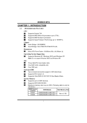
... 32bit PCI bus master slots. One CNR slot. Supports HyperTransport Technology up to 1600MT/s. Note: Do not support Windows 98SE and Windows ME. Supports PIO mode 0~4. Supports DDR-266/333/400. K8M800-M7A CHAPTER 1: INTRODUCTION 1.1 MOTHERBOARD FEATURES CPU Supports Socket 754. Supports AMD Athlon 64 processor up to 3700+. South Bridge: VIA VT8237R/VT8237R PLUS. On-board IDE Two on-board connectors support 4 IDE disk drives. Maximum memory size is up to 2GB. (Following table is only for reference.) DIMM Socket Location...
... 32bit PCI bus master slots. One CNR slot. Supports HyperTransport Technology up to 1600MT/s. Note: Do not support Windows 98SE and Windows ME. Supports PIO mode 0~4. Supports DDR-266/333/400. K8M800-M7A CHAPTER 1: INTRODUCTION 1.1 MOTHERBOARD FEATURES CPU Supports Socket 754. Supports AMD Athlon 64 processor up to 3700+. South Bridge: VIA VT8237R/VT8237R PLUS. On-board IDE Two on-board connectors support 4 IDE disk drives. Maximum memory size is up to 2GB. (Following table is only for reference.) DIMM Socket Location...
K8M800-M7A user's manual
Page 4
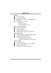
... Monitor Fan Speed Controller ITE's "Smart Guardian" function Onboard AC'97 Sound Codec Chip: REALTEK ALC655. Supports RAID 0 and RAID 1 functions. Supports 2 serial ATA (SATA) ports. - Supports 10 Mb/s and 100 Mb/s auto-negotiation. Low Pin Count Interface. Supports S/PDIF out function. Data transfer rates up to 150 MB/s. - Compliant with AC'97 Version 2.3 specification. Half/Full duplex capability. Support 6 channels. Compliant with SATA Version 1.0 specification. 10/100 LAN PHY PHY: RTL8201BL/CL. Supports ACPI, PCI power management. 2 Onboard Serial...
... Monitor Fan Speed Controller ITE's "Smart Guardian" function Onboard AC'97 Sound Codec Chip: REALTEK ALC655. Supports RAID 0 and RAID 1 functions. Supports 2 serial ATA (SATA) ports. - Supports 10 Mb/s and 100 Mb/s auto-negotiation. Low Pin Count Interface. Supports S/PDIF out function. Data transfer rates up to 150 MB/s. - Compliant with AC'97 Version 2.3 specification. Half/Full duplex capability. Support 6 channels. Compliant with SATA Version 1.0 specification. 10/100 LAN PHY PHY: RTL8201BL/CL. Supports ACPI, PCI power management. 2 Onboard Serial...
K8M800-M7A user's manual
Page 5
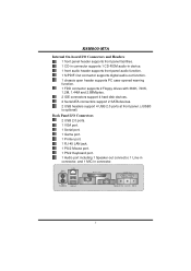
...front panel audio function. 1 S/PDIF-Out connector supports digital audio-out function. 1 chassis open header supports PC case-opened warning function. 1 FDD connector supports 2 Floppy drives with 360K, 720K, 1.2M, 1.44M and 2.88Mbytes. 2 IDE connectors support 4 hard disk devices. 2 Serial ATA connectors support 2 SATA devices. 2 USB headers support 4 USB 2.0 ports at front panel. (JUSB3 is optional) Back Panel I/O Connectors 2 USB 2.0 ports. 1 VGA port. 1 Serial port. 1 Game port. 1 Printer port. 1 RJ-45 LAN jack. 1 PS/2 Mouse port. 1 PS/2 Keyboard port. 1 Audio port including 1 Speaker-out...
...front panel audio function. 1 S/PDIF-Out connector supports digital audio-out function. 1 chassis open header supports PC case-opened warning function. 1 FDD connector supports 2 Floppy drives with 360K, 720K, 1.2M, 1.44M and 2.88Mbytes. 2 IDE connectors support 4 hard disk devices. 2 Serial ATA connectors support 2 SATA devices. 2 USB headers support 4 USB 2.0 ports at front panel. (JUSB3 is optional) Back Panel I/O Connectors 2 USB 2.0 ports. 1 VGA port. 1 Serial port. 1 Game port. 1 Printer port. 1 RJ-45 LAN jack. 1 PS/2 Mouse port. 1 PS/2 Keyboard port. 1 Audio port including 1 Speaker-out...
K8M800-M7A user's manual
Page 8
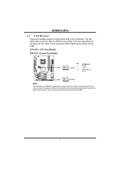
... support 3-pin head connector. When connecting with wires onto connectors, please note that the red wire is the positive and should be connected to pin#2, and the black wire is Ground and should be different according to the fan manufacturer. Connect the fan cable to the connector while matching the black wire to GND. 6 K8M800-M7A 2.2 FAN HEADERS These fan headers support cooling-fans built in the computer. The fan cable and connector may be connected to pin...
... support 3-pin head connector. When connecting with wires onto connectors, please note that the red wire is the positive and should be connected to pin#2, and the black wire is Ground and should be different according to the fan manufacturer. Connect the fan cable to the connector while matching the black wire to GND. 6 K8M800-M7A 2.2 FAN HEADERS These fan headers support cooling-fans built in the computer. The fan cable and connector may be connected to pin...
K8M800-M7A user's manual
Page 10
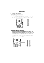
... IDE connectors can connect a master and a slave drive, so you can connect up to IDE1. 40 39 2 IDE1 1 IDE2 8 The first hard drive should always be connected to four hard disk drives. This connector supports the provided floppy drive ribbon cables. 34 33 2 1 IDE1/IDE2: Hard Disk Connectors The motherboard has a 32-bit Enhanced PCI IDE Controller that supports 360K, 720K, 1.2M, 1.44M and 2.88M floppy disk types. K8M800-M7A 2.4 CONNECTORS AND SLOTS FDD1: Floppy Disk Connector The motherboard provides a standard floppy disk connector that provides PIO Mode 0~4, Bus Master...
... IDE connectors can connect a master and a slave drive, so you can connect up to IDE1. 40 39 2 IDE1 1 IDE2 8 The first hard drive should always be connected to four hard disk drives. This connector supports the provided floppy drive ribbon cables. 34 33 2 1 IDE1/IDE2: Hard Disk Connectors The motherboard has a 32-bit Enhanced PCI IDE Controller that supports 360K, 720K, 1.2M, 1.44M and 2.88M floppy disk types. K8M800-M7A 2.4 CONNECTORS AND SLOTS FDD1: Floppy Disk Connector The motherboard provides a standard floppy disk connector that provides PIO Mode 0~4, Bus Master...
K8M800-M7A user's manual
Page 11
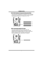
... a bus standard for improved video efficiency and performance, especially with 3D graphics. 9 PCI1 PCI2 PCI3 AGP1: Accelerated Graphics Port Slot Your monitor will take advantage of AGP technology for expansion cards. K8M800-M7A PCI1~PCI3: Peripheral Component Interconnect Slots This motherboard is designated as 32 bits. An AGP card will attach directly to that video card. This PCI slot is equipped with an Accelerated Graphics Port (AGP). This motherboard supports video cards for PCI slots, but...
... a bus standard for improved video efficiency and performance, especially with 3D graphics. 9 PCI1 PCI2 PCI3 AGP1: Accelerated Graphics Port Slot Your monitor will take advantage of AGP technology for expansion cards. K8M800-M7A PCI1~PCI3: Peripheral Component Interconnect Slots This motherboard is designated as 32 bits. An AGP card will attach directly to that video card. This PCI slot is equipped with an Accelerated Graphics Port (AGP). This motherboard supports video cards for PCI slots, but...
K8M800-M7A user's manual
Page 13
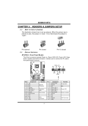
...6 N/A 8 Power LED (+) Hard drive LED 10 Power LED (+) 12 Power LED (-) Reset button 14 Power button 16 Ground 18 Key IrDA Connector 20 Key 22 Ground 24 IRRX Function Sleep button N/A Power LED Power-on pins, the jumper is "close", if not, that means the jumper is placed on button IrDA Connector 11 When the jumper cap is "open". Pin opened Pin closed Pin1-2 closed 3.2 DETAIL SETTINGS JPANEL1: Front Panel Header This 24-pin connector includes Power-on, Reset, HDD LED, Power LED, Sleep button, speaker and IrDA Connection. PWR_LED SLP On/Off ++ 2 1 +- K8M800-M7A...
...6 N/A 8 Power LED (+) Hard drive LED 10 Power LED (+) 12 Power LED (-) Reset button 14 Power button 16 Ground 18 Key IrDA Connector 20 Key 22 Ground 24 IRRX Function Sleep button N/A Power LED Power-on pins, the jumper is "close", if not, that means the jumper is placed on button IrDA Connector 11 When the jumper cap is "open". Pin opened Pin closed Pin1-2 closed 3.2 DETAIL SETTINGS JPANEL1: Front Panel Header This 24-pin connector includes Power-on, Reset, HDD LED, Power LED, Sleep button, speaker and IrDA Connection. PWR_LED SLP On/Off ++ 2 1 +- K8M800-M7A...
K8M800-M7A user's manual
Page 14
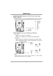
... to connect additional USB cable on Pin 2-3 individually. 12 JUSBV2: USB ports at front panel (JUSB1/JUSB2/JUSB3) are powered by +5V standby voltage. K8M800-M7A JUSB1/JUSB2/JUSB3: Headers for USB 2.0 Ports at Front Panel (JUSB3 is optional) This header allows user to support this function "Power-On system via USB device," "JUSBV1/ JUSBV2" jumper cap should be placed on the PC front panel, and also can be connected with internal USB devices, like USB card reader. Pin Assignment...
... to connect additional USB cable on Pin 2-3 individually. 12 JUSBV2: USB ports at front panel (JUSB1/JUSB2/JUSB3) are powered by +5V standby voltage. K8M800-M7A JUSB1/JUSB2/JUSB3: Headers for USB 2.0 Ports at Front Panel (JUSB3 is optional) This header allows user to support this function "Power-On system via USB device," "JUSBV1/ JUSBV2" jumper cap should be placed on the PC front panel, and also can be connected with internal USB devices, like USB card reader. Pin Assignment...
K8M800-M7A user's manual
Page 15
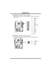
K8M800-M7A JATXPWR1: ATX Power Source Connector This connector allows user to CPU power circuit. Pin Assignment 1 +3.3V 2 +3.3V 3 Ground 4 +5V 10 20 5 Ground 6 +5V 7 Ground 8 PW_OK 9 Standby Voltage +5V 10 +12V 11 +3.3V 12 -12V 13 Ground 1 11 14 PS_ON 15 Ground 16 Ground 17 Ground 18 -5V 19 +5V 20 +5V JATXPWR2: ATX Power Source Connector By connecting this connector, it will provide +12V to connect 20-pin power connector on the ATX power supply. Pin Assignment 4 3 1 +12V 2 1 2 +12V 3 Ground 4 Ground 13
K8M800-M7A JATXPWR1: ATX Power Source Connector This connector allows user to CPU power circuit. Pin Assignment 1 +3.3V 2 +3.3V 3 Ground 4 +5V 10 20 5 Ground 6 +5V 7 Ground 8 PW_OK 9 Standby Voltage +5V 10 +12V 11 +3.3V 12 -12V 13 Ground 1 11 14 PS_ON 15 Ground 16 Ground 17 Ground 18 -5V 19 +5V 20 +5V JATXPWR2: ATX Power Source Connector By connecting this connector, it will provide +12V to connect 20-pin power connector on the ATX power supply. Pin Assignment 4 3 1 +12V 2 1 2 +12V 3 Ground 4 Ground 13
K8M800-M7A user's manual
Page 16
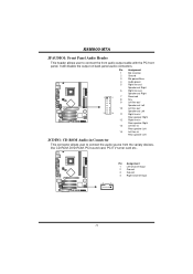
... speaker Left 14 Left line in/ Rear speaker Left JCDIN1: CD-ROM Audio-in Connector This connector allows user to connect the front audio output cable with the PC front panel. K8M800-M7A JFAUDIO1: Front Panel Audio Header This header allows user to connect the audio source from the variaty devices, like CD-ROM, DVD-ROM, PCI sound card, PCI TV turner card etc.. 4 1 Pin Assignment 1 Left Channel Input 2 Ground 3 Ground 4 Right Channel Input 14 It will disable the output on back panel audio connectors...
... speaker Left 14 Left line in/ Rear speaker Left JCDIN1: CD-ROM Audio-in Connector This connector allows user to connect the front audio output cable with the PC front panel. K8M800-M7A JFAUDIO1: Front Panel Audio Header This header allows user to connect the audio source from the variaty devices, like CD-ROM, DVD-ROM, PCI sound card, PCI TV turner card etc.. 4 1 Pin Assignment 1 Left Channel Input 2 Ground 3 Ground 4 Right Channel Input 14 It will disable the output on back panel audio connectors...
K8M800-M7A user's manual
Page 17
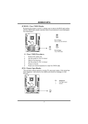
...: Chassis Open Header This connector allows system to "Pin 2-3 close ". 5. K8M800-M7A JCMOS1: Clear CMOS Header By placing the jumper on next boot-up. Set the jumper to monitor PC case open signal 2 Ground 2 1 15 Reset your desired password or clear the CMOS data. If the signal has been triggered, it will record to the CMOS and show the message on pin2-3, it allows user to restore the BIOS safe setting and the CMOS...
...: Chassis Open Header This connector allows system to "Pin 2-3 close ". 5. K8M800-M7A JCMOS1: Clear CMOS Header By placing the jumper on next boot-up. Set the jumper to monitor PC case open signal 2 Ground 2 1 15 Reset your desired password or clear the CMOS data. If the signal has been triggered, it will record to the CMOS and show the message on pin2-3, it allows user to restore the BIOS safe setting and the CMOS...
K8M800-M7A user's manual
Page 18
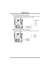
K8M800-M7A JSATA1~JSATA2: Serial ATA Connectors The motherboard has a PCI to SATA Controller with 2 channels SATA interface, it satisfies the SATA 1.0 spec and with transfer rate of 1.5GB/s. 741 Pin Assignment 1 Ground 2 TX+ 3 TX4 Ground 5 RX6 RX+ 7 Ground JSATA1 JSPDIF_OUT1: Digital Audio-out Connector This connector allows user to connect the PCI bracket SPDIF output header. 1 3 Pin Assignment 1 +5V 2 SPDIF_OUT 3 Ground 16
K8M800-M7A JSATA1~JSATA2: Serial ATA Connectors The motherboard has a PCI to SATA Controller with 2 channels SATA interface, it satisfies the SATA 1.0 spec and with transfer rate of 1.5GB/s. 741 Pin Assignment 1 Ground 2 TX+ 3 TX4 Ground 5 RX6 RX+ 7 Ground JSATA1 JSPDIF_OUT1: Digital Audio-out Connector This connector allows user to connect the PCI bracket SPDIF output header. 1 3 Pin Assignment 1 +5V 2 SPDIF_OUT 3 Ground 16
K8M800-M7A user's manual
Page 19
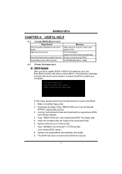
... update BIOS or BIOS is shown after boot-up Long beeps every other second Meaning Video card not found or video card memory bad CPU overheated System will shut down automatically No error found during POST No DRAM detected or install 4.2 EXTRA INFORMATION A. Download the Flash Utility "AWDFLASH.exe" from Biostar website. 4. System will help to DOS prompt. 7. System will work properly. 17 If the following message is invaded by two short beeps High...
... update BIOS or BIOS is shown after boot-up Long beeps every other second Meaning Video card not found or video card memory bad CPU overheated System will shut down automatically No error found during POST No DRAM detected or install 4.2 EXTRA INFORMATION A. Download the Flash Utility "AWDFLASH.exe" from Biostar website. 4. System will help to DOS prompt. 7. System will work properly. 17 If the following message is invaded by two short beeps High...
K8M800-M7A user's manual
Page 20
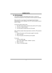
... the CPU surface. 2. Clear the CMOS data. (See "Close CMOS Header: JCMOS1" section) 2. CPU fan speed is placed evenly with the CPU speed. After confirmed, please follow steps below to avoid a damage of the CPU, and the system may not power on the system again. 18 Wait for seconds, that means the CPU protection function has been activated. CPU fan is over heated, the motherboard will...
... the CPU surface. 2. Clear the CMOS data. (See "Close CMOS Header: JCMOS1" section) 2. CPU fan speed is placed evenly with the CPU speed. After confirmed, please follow steps below to avoid a damage of the CPU, and the system may not power on the system again. 18 Wait for seconds, that means the CPU protection function has been activated. CPU fan is over heated, the motherboard will...
K8M800-M7A user's manual
Page 21
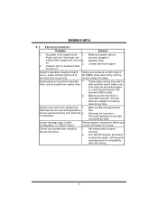
... applications files. Reformat the hard drive. Screen message says "Invalid Configuration" or "CMOS Failure." inside power supply does not turn on . 3. Set master/slave jumpers correctly. 2. No power to disk controller board. System inoperative. drive, can be booted from hard disk 2. is extremely important. Contact technical support. 2. Cannot boot system after installing second hard drive. 1. Re-install applications and data using backup disks. Call the drive manufacturers for compatibility with other drives. 19 Keyboard lights are capable...
... applications files. Reformat the hard drive. Screen message says "Invalid Configuration" or "CMOS Failure." inside power supply does not turn on . 3. Set master/slave jumpers correctly. 2. No power to disk controller board. System inoperative. drive, can be booted from hard disk 2. is extremely important. Contact technical support. 2. Cannot boot system after installing second hard drive. 1. Re-install applications and data using backup disks. Call the drive manufacturers for compatibility with other drives. 19 Keyboard lights are capable...
K8M800-M7A user's manual
Page 22
K8M800-M7A CHAPTER 5: WARPSPEEDER™ 5.1 INTRODUCTION [WarpSpeeder™], a new powerful control utility, features three user-friendly functions including Overclock Manager, Overvoltage Manager, and Hardware Monitor. The cool Hardware Monitor smartly indicates the temperatures, voltage and CPU fan speed as well as the chipset information. Also, in system fail or hang, [WarpSpeeder™] technology assures the system stability by automatically rebooting the computer and then restart to a speed that...
K8M800-M7A CHAPTER 5: WARPSPEEDER™ 5.1 INTRODUCTION [WarpSpeeder™], a new powerful control utility, features three user-friendly functions including Overclock Manager, Overvoltage Manager, and Hardware Monitor. The cool Hardware Monitor smartly indicates the temperatures, voltage and CPU fan speed as well as the chipset information. Also, in system fail or hang, [WarpSpeeder™] technology assures the system stability by automatically rebooting the computer and then restart to a speed that...
K8M800-M7A user's manual
Page 23
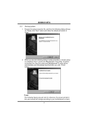
... setup is checked, the Tray Icon utility and [WarpSpeeder™] utility will be automatically and immediately launched after you see the following dialog will change according to install. 2. K8M800-M7A 5.3 INSTALLATION 1. Execute the setup execution file, and then the following dialog in this user manual will pop up. When you click "Finish" button. Please click "Next" button and follow the default procedure to your motherboard...
... setup is checked, the Tray Icon utility and [WarpSpeeder™] utility will be automatically and immediately launched after you see the following dialog will change according to install. 2. K8M800-M7A 5.3 INSTALLATION 1. Execute the setup execution file, and then the following dialog in this user manual will pop up. When you click "Finish" button. Please click "Next" button and follow the default procedure to your motherboard...
K8M800-M7A user's manual
Page 25
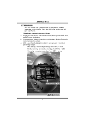
... figure; Display the CPU Speed, CPU external clock, Memory clock, AGP clock, and PCI clock information. With a user-friendly Status Animation, it can represent 3 overclock percentage stages: Man walking→overclock percentage from 100% ~ 110 % Panther running→overclock percentage from 110% ~ 120% Car racing→overclock percentage from 120% ~ above 23 the utility's first window you click the tray icon, [WarpSpeeder™] utility will see is Main Panel. b. Main Panel contains...
... figure; Display the CPU Speed, CPU external clock, Memory clock, AGP clock, and PCI clock information. With a user-friendly Status Animation, it can represent 3 overclock percentage stages: Man walking→overclock percentage from 100% ~ 110 % Panther running→overclock percentage from 110% ~ 120% Car racing→overclock percentage from 120% ~ above 23 the utility's first window you click the tray icon, [WarpSpeeder™] utility will see is Main Panel. b. Main Panel contains...
K8M800-M7A user's manual
Page 28
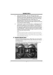
...™] utility will proceed a testing for Direct3D rendering. 5. "Auto-overclock button": User can click this panel, you can get the real-time status information of testing until system fail. In this button and [WarpSpeeder™] will restore to the hardware default setting or load the verified best and stable frequency according to the Recovery Dialog's setting. Hardware Monitor Panel Click the Hardware Monitor button in Auto-overclock and Verify...
...™] utility will proceed a testing for Direct3D rendering. 5. "Auto-overclock button": User can click this panel, you can get the real-time status information of testing until system fail. In this button and [WarpSpeeder™] will restore to the hardware default setting or load the verified best and stable frequency according to the Recovery Dialog's setting. Hardware Monitor Panel Click the Hardware Monitor button in Auto-overclock and Verify...


