Installation Manual
Page 1
Owners and Installation Manual MMD70 7" LCD MONITOR & DVD PLAYER
Owners and Installation Manual MMD70 7" LCD MONITOR & DVD PLAYER
Installation Manual
Page 2
... screen. Reverse engineering or disassembly is dirty. Lock the LCD screen in the fully closed position when not in the off or auto positions when the vehicle is unattended, as the dome lights, if left on, can drain the vehicle's battery. Remember to the lowest position. Do not put pressure on headphones always adjust the volume setting to leave the dome light switch...
... screen. Reverse engineering or disassembly is dirty. Lock the LCD screen in the fully closed position when not in the off or auto positions when the vehicle is unattended, as the dome lights, if left on, can drain the vehicle's battery. Remember to the lowest position. Do not put pressure on headphones always adjust the volume setting to leave the dome light switch...
Installation Manual
Page 3
... the driver's seat where it will not be installed in a motor vehicle and visible to the operator of the motor vehicle. 3 An LCD panel or video monitor used for television reception, video or DVD play that operates when the vehicle is in "park" or when the vehicle's parking brake is used for vehicle information, system control, rear or side observation or navigation. Important Notice An LCD panel and/or video monitor...
... the driver's seat where it will not be installed in a motor vehicle and visible to the operator of the motor vehicle. 3 An LCD panel or video monitor used for television reception, video or DVD play that operates when the vehicle is in "park" or when the vehicle's parking brake is used for vehicle information, system control, rear or side observation or navigation. Important Notice An LCD panel and/or video monitor...
Installation Manual
Page 4
... Crystal Display (LCD) monitor and a built-in this may result in installing the system properly to disassemble the cabinet. The unit is a risk of reliable, trouble-free service. To ensure proper ventilation and proper operation, never cover or block the slots and openings with this manual for selecting the MMD70. A. Please store this product prior to Laser Radiation. Cleaning Unit When cleaning, make sure...
... Crystal Display (LCD) monitor and a built-in this may result in installing the system properly to disassemble the cabinet. The unit is a risk of reliable, trouble-free service. To ensure proper ventilation and proper operation, never cover or block the slots and openings with this manual for selecting the MMD70. A. Please store this product prior to Laser Radiation. Cleaning Unit When cleaning, make sure...
Installation Manual
Page 5
... cloth. A/V Adapter Cable 3. Power/Domelight Harness 4. Hardware Package 4 pcs M3.5 x 18mm Panhead Philips Machines Screws 2 pcs Rubber Plugs 5. Instruction Manual 5 Disc Do not use disc of discs may be available. Some playback operations of 8cm for the unit's shortage. Do not stick paper, tape or glue on the disc. Do not touch the surface of disc. Mounting Plate 7. Since this unit plays discs according to the disc contents the software producers...
... cloth. A/V Adapter Cable 3. Power/Domelight Harness 4. Hardware Package 4 pcs M3.5 x 18mm Panhead Philips Machines Screws 2 pcs Rubber Plugs 5. Instruction Manual 5 Disc Do not use disc of discs may be available. Some playback operations of 8cm for the unit's shortage. Do not stick paper, tape or glue on the disc. Do not touch the surface of disc. Mounting Plate 7. Since this unit plays discs according to the disc contents the software producers...
Installation Manual
Page 6
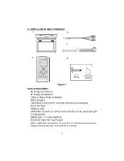
to mark headliner Scribe (to vehicle. 6 D. Requirements will vary from vehicle to mark trim ring if used) Misc. INSTALLATION AND POWERING 1. 2. 3. 5. 4. 3 (X 4) (X 2) Figure 1 TOOLS REQUIRED: #2 Philips Screwdriver #1 Philips Screwdriver Utility or Razor Knife or Shears Wire Strippers Upholstery hook tool (for removal of panels as necessary) Electrical Tape Masking Tape Multimeter (to vehicle power source). electrical connectors (to connect to verify 12 volt DC and continuity: Do not use a test light or logic probe) Marker pen -
to mark headliner Scribe (to vehicle. 6 D. Requirements will vary from vehicle to mark trim ring if used) Misc. INSTALLATION AND POWERING 1. 2. 3. 5. 4. 3 (X 4) (X 2) Figure 1 TOOLS REQUIRED: #2 Philips Screwdriver #1 Philips Screwdriver Utility or Razor Knife or Shears Wire Strippers Upholstery hook tool (for removal of panels as necessary) Electrical Tape Masking Tape Multimeter (to vehicle power source). electrical connectors (to connect to verify 12 volt DC and continuity: Do not use a test light or logic probe) Marker pen -
Installation Manual
Page 7
... as necessary. (Refer to the Wiring Diagrams on page 10 of this manual as well as all areas where interconnecting wire harnesses will not be located. GENERAL INSTALLATION APPROACH: 1) Decide upon system configuration and options that will be installed (i.e.: what components, VCP, Tuner, RF Modulator/external amp, remote headphones, DVD, etc.). 2) Review all manuals to become familiar with electrical requirements and hook ups. 3) Decide upon mounting...
... as necessary. (Refer to the Wiring Diagrams on page 10 of this manual as well as all areas where interconnecting wire harnesses will not be located. GENERAL INSTALLATION APPROACH: 1) Decide upon system configuration and options that will be installed (i.e.: what components, VCP, Tuner, RF Modulator/external amp, remote headphones, DVD, etc.). 2) Review all manuals to become familiar with electrical requirements and hook ups. 3) Decide upon mounting...
Installation Manual
Page 8
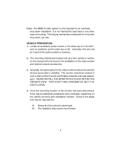
... may need to vehicle, so this wire can be found at the ignition switch or fuse-box. 2) The mounting method and location will vary from vehicle to be additional preparation work necessary, depending on the installation of mounting. The monitor should be located in the ACC. VEHICLE PREPARATION: 1) Locate an accessory power source (+12v when key is off). Generally, this manual will only...
... may need to vehicle, so this wire can be found at the ignition switch or fuse-box. 2) The mounting method and location will vary from vehicle to be additional preparation work necessary, depending on the installation of mounting. The monitor should be located in the ACC. VEHICLE PREPARATION: 1) Locate an accessory power source (+12v when key is off). Generally, this manual will only...
Installation Manual
Page 10
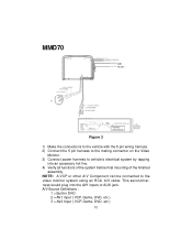
MMD70 (RED) (BLACK) Figure 3 1) Make the connections to the vehicle with the 5 pin wiring harness. 2) Connect the 5 pin harness to the mating connector on the Video Monitor. 3) Connect power harness to the video monitor system using an RCA A/V cable. NOTE: A VCP or other A/V Component can be connected to vehicle's electrical system by tapping into the AV1 inputs or AUX jack. This second harness would plug into an accessory hot line. 4) Verify all functions of the system before final mounting...
MMD70 (RED) (BLACK) Figure 3 1) Make the connections to the vehicle with the 5 pin wiring harness. 2) Connect the 5 pin harness to the mating connector on the Video Monitor. 3) Connect power harness to the video monitor system using an RCA A/V cable. NOTE: A VCP or other A/V Component can be connected to vehicle's electrical system by tapping into the AV1 inputs or AUX jack. This second harness would plug into an accessory hot line. 4) Verify all functions of the system before final mounting...
Installation Manual
Page 11
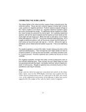
... video monitor require three connections to ground. There are two common types of these wires will switch to the vehicle's wiring. When the light is activated, one of dome light circuits used, positive or negative switched. Positive systems supply voltage to the interior lights to turn them on Ford vehicles. Negative systems are commonly found on ) wire to a fused constant 12 volt source and the black / red (lamp common) wire...
... video monitor require three connections to ground. There are two common types of these wires will switch to the vehicle's wiring. When the light is activated, one of dome light circuits used, positive or negative switched. Positive systems supply voltage to the interior lights to turn them on Ford vehicles. Negative systems are commonly found on ) wire to a fused constant 12 volt source and the black / red (lamp common) wire...
Installation Manual
Page 13
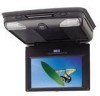
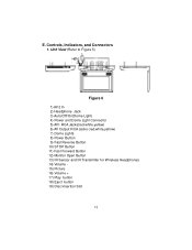
Unit View (Refer to Figure 5) Figure 6 1) AV 2 In 2) Headphone Jack 3) Auto/Off/On(Dome Light) 4) Power and Dome Light Connector 5) AV1 RCA Jacks(red,white,yellow) 6) AV Output RCA Jacks (red,white,yellow) 7) Dome Lights 8) Power Button 9) Fast Reverse Button 10) STOP Button 11) Fast Forward Button 12) Monitor Open Button 13) IR Sensor and IR Transmitter for Wireless Headphones 14) Volume 15) Picture 16) Volume + 17) Play button 18) Eject button 19) Disc Insertion Slot 13 Controls, Indicators, and Connectors 1. E.
Unit View (Refer to Figure 5) Figure 6 1) AV 2 In 2) Headphone Jack 3) Auto/Off/On(Dome Light) 4) Power and Dome Light Connector 5) AV1 RCA Jacks(red,white,yellow) 6) AV Output RCA Jacks (red,white,yellow) 7) Dome Lights 8) Power Button 9) Fast Reverse Button 10) STOP Button 11) Fast Forward Button 12) Monitor Open Button 13) IR Sensor and IR Transmitter for Wireless Headphones 14) Volume 15) Picture 16) Volume + 17) Play button 18) Eject button 19) Disc Insertion Slot 13 Controls, Indicators, and Connectors 1. E.
Installation Manual
Page 14
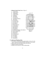
.... Remote Control View (Refer to Figure 7) 1) Power Button 2) Display Button 3) Angle Button 4) Subtitle Button 5) A-B Button 6) Slow Button 7) Pause Button 8) Fast Reverse Button 9) Stop Button 10) Picture Button 11) DVD /AV1 /AV2 12) Zoom Button 13) Eject Button 14) Numeric Buttons 15) Audio Button 16) Repeat Button 17) Menu Button 18) Setup Button 19) Up/Down/Left/Right / Enter Buttons 20) Fast Forward Button 21) Return Button 22) Play Button 23) Previous Button 24) Next Button 25) Vol- d. Rotate the LCD Screen for a good viewing angle. 14 2. Select DVD using the DVD/AV1...
.... Remote Control View (Refer to Figure 7) 1) Power Button 2) Display Button 3) Angle Button 4) Subtitle Button 5) A-B Button 6) Slow Button 7) Pause Button 8) Fast Reverse Button 9) Stop Button 10) Picture Button 11) DVD /AV1 /AV2 12) Zoom Button 13) Eject Button 14) Numeric Buttons 15) Audio Button 16) Repeat Button 17) Menu Button 18) Setup Button 19) Up/Down/Left/Right / Enter Buttons 20) Fast Forward Button 21) Return Button 22) Play Button 23) Previous Button 24) Next Button 25) Vol- d. Rotate the LCD Screen for a good viewing angle. 14 2. Select DVD using the DVD/AV1...
Installation Manual
Page 15
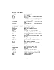
... point B of the disc Display disc information (title, chapter, track, time, etc.) Change the angles on the scene Select the subtitle language and turn it on/ off Select the audio language Enlarge an image to 2 or 3 times the original Display the setup menu to select and set items, and exit the setup menu. Select source DVD, AV1, AV2 Eject disc Brightness/Contrast/Tint/Color Reduce volume/Lower picture setting Increase volume/Raise picture setting Previous chapter/track...
... point B of the disc Display disc information (title, chapter, track, time, etc.) Change the angles on the scene Select the subtitle language and turn it on/ off Select the audio language Enlarge an image to 2 or 3 times the original Display the setup menu to select and set items, and exit the setup menu. Select source DVD, AV1, AV2 Eject disc Brightness/Contrast/Tint/Color Reduce volume/Lower picture setting Increase volume/Raise picture setting Previous chapter/track...
Installation Manual
Page 16
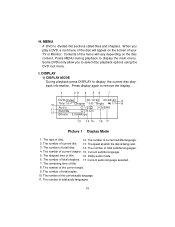
... angle. 9. Press MENU during playback to select disc playback options using the DVD root menu. The number of total angles. 10. The number of total chapters. 17. Some DVDs only allow you play a DVD, a root menu of the disc will vary depending on the screen of title. 8. The remaining time of your TV or Monitor. When you to display the main menu. MENU A DVD is being read. 3. I. Picture 1 Display Mode 1. The type...
... angle. 9. Press MENU during playback to select disc playback options using the DVD root menu. The number of total angles. 10. The number of total chapters. 17. Some DVDs only allow you play a DVD, a root menu of the disc will vary depending on the screen of title. 8. The remaining time of your TV or Monitor. When you to display the main menu. MENU A DVD is being read. 3. I. Picture 1 Display Mode 1. The type...
Installation Manual
Page 20
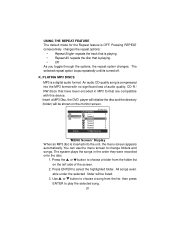
... through the options, the repeat option changes. All songs available under the selected folder will be listed. 3. Use or button to choose a song from the folder list on the monitor screen. 'MENU Screen' Display When an MP3 disc is playing. • Repeat All- Press ENTER to play the selected song. 20 repeats the track that is compressed into the unit, the menu screen appears automatically.
... through the options, the repeat option changes. All songs available under the selected folder will be listed. 3. Use or button to choose a song from the folder list on the monitor screen. 'MENU Screen' Display When an MP3 disc is playing. • Repeat All- Press ENTER to play the selected song. 20 repeats the track that is compressed into the unit, the menu screen appears automatically.
Installation Manual
Page 26
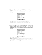
... the Screen Saver mode after approximately five minutes if the same image remains on the disc. Select 'Last Memory' using the UP/DOWN button and then press ENTER to the last position on the screen. *Off: Disables screen saver (off using the UP/DOWN button, then press ENTER/LEFT to confirm the setting and exit. 'Screen Saver' Display *On: Enables screen saver *NOTE: The DVD player will...
... the Screen Saver mode after approximately five minutes if the same image remains on the disc. Select 'Last Memory' using the UP/DOWN button and then press ENTER to the last position on the screen. *Off: Disables screen saver (off using the UP/DOWN button, then press ENTER/LEFT to confirm the setting and exit. 'Screen Saver' Display *On: Enables screen saver *NOTE: The DVD player will...

Installation Manual
Page 27
... ENTER to the default settings select 'LOAD FACTORY' using the UP/DOWN button. Load Factory: To restore all of users while some discs can record this default password in another area and delete it from this manual. 3) Select 'Rating' by using the LEFT/RIGHT button. 'Rating' Display Select 'Password' using the UP/DOWN button and press ENTER. Input the password (For the first time use the default password is 3308.
... ENTER to the default settings select 'LOAD FACTORY' using the UP/DOWN button. Load Factory: To restore all of users while some discs can record this default password in another area and delete it from this manual. 3) Select 'Rating' by using the LEFT/RIGHT button. 'Rating' Display Select 'Password' using the UP/DOWN button and press ENTER. Input the password (For the first time use the default password is 3308.
Installation Manual
Page 28
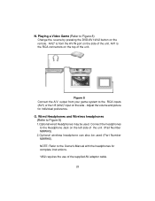
... port on the side . O. Connect the headphones to Figure 8) Change the source by pressing the DVD/AV1/AV2 button on the left side of the unit. Playing a Video Game (Refer to the Headphone Jack on the remote. N. AV1 is from your game system to the RCA inputs (AV1) or the 1/8 (AV2)* input on the side of the supplied AV adaptor cable. 28 Adjust the volume and picture...
... port on the side . O. Connect the headphones to Figure 8) Change the source by pressing the DVD/AV1/AV2 button on the left side of the unit. Playing a Video Game (Refer to the Headphone Jack on the remote. N. AV1 is from your game system to the RCA inputs (AV1) or the 1/8 (AV2)* input on the side of the supplied AV adaptor cable. 28 Adjust the volume and picture...
Installation Manual
Page 29
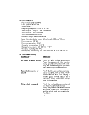
... the correct source is selected (i.e.: DVD, AV1 or AV2). P. Power but no video or sound -Verify that power is on and playing a known good media (such as a videotape). Verify connections at 2 pin Power Harness. make sure the modulator and the vehicle radio are turned on Red wire at 2 pin Power Harness behind video monitor. Verify ground connection with continuity test from known good ground to 20 kHz Video output: 1 Vp-p/75 Ohm, unbalanced Audio output: 1.4Vrms/10kOhm Audio S/N: Better...
... the correct source is selected (i.e.: DVD, AV1 or AV2). P. Power but no video or sound -Verify that power is on and playing a known good media (such as a videotape). Verify connections at 2 pin Power Harness. make sure the modulator and the vehicle radio are turned on Red wire at 2 pin Power Harness behind video monitor. Verify ground connection with continuity test from known good ground to 20 kHz Video output: 1 Vp-p/75 Ohm, unbalanced Audio output: 1.4Vrms/10kOhm Audio S/N: Better...
Installation Manual
Page 30
... been damaged through alteration, improper installation, mishandling, misuse, neglect, accident, or by removal or defacement of the factory serial number/bar code label(s). U.S.A. : AEC 150 MARCUS BLVD., HAUPPAUGE, NEW YORK 11788 l 1-800-645-4994 CANADA : CALL 1-800-645-4994 FOR LOCATION OF WARRANTY STATION SERVING YOUR AREA 128-6429E © 2005 Audiovox Electronics Corporation 30 This Warranty does...
... been damaged through alteration, improper installation, mishandling, misuse, neglect, accident, or by removal or defacement of the factory serial number/bar code label(s). U.S.A. : AEC 150 MARCUS BLVD., HAUPPAUGE, NEW YORK 11788 l 1-800-645-4994 CANADA : CALL 1-800-645-4994 FOR LOCATION OF WARRANTY STATION SERVING YOUR AREA 128-6429E © 2005 Audiovox Electronics Corporation 30 This Warranty does...


