Motherboard DIY Troubleshooting Guide
Page 1
Motherboard P4S800-MX Manuel
Motherboard P4S800-MX Manuel
Motherboard DIY Troubleshooting Guide
Page 39
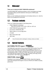
...complete, reboot the system. 2.1.5 ASUS Update The ASUS Update is a utility that allows you to update the motherboard BIOS in the support CD that comes with the motherboard package. The Drivers menu appears. 2. To update the BIOS using the ASUS Update: 1. Checking for the...! To install ASUS Update: 1. The ASUS Update utility is available in Windows® environment. Reading file "P4S800MX.BIN". Select your system. This utility is copied into the CD-ROM drive. The ASUS Update initial screen appears. 2. See page 3-3 for floppy... Manuel ASUS P4S800-MX 2-7 Bad...
...complete, reboot the system. 2.1.5 ASUS Update The ASUS Update is a utility that allows you to update the motherboard BIOS in the support CD that comes with the motherboard package. The Drivers menu appears. 2. To update the BIOS using the ASUS Update: 1. Checking for the...! To install ASUS Update: 1. The ASUS Update utility is available in Windows® environment. Reading file "P4S800MX.BIN". Select your system. This utility is copied into the CD-ROM drive. The ASUS Update initial screen appears. 2. See page 3-3 for floppy... Manuel ASUS P4S800-MX 2-7 Bad...

P4S800-MX English User Manual E1447
Page 1
Motherboard P4S800-MX User Guide
Motherboard P4S800-MX User Guide

P4S800-MX English User Manual E1447
Page 3
Contents Notices v Safety information vi P4S800-MX specification summary vii About this guide viii Chapter 1: Product introduction 1.1 Welcome 1-2 1.2 Package contents 1-2 1.3 Special features 1-2 1.4 Before you proceed 1-5 Onboard LED 1-5 1.5 Motherboard overview 1-6 1.5.1 Motherboard layout 1-6 1.5.2 Placement direction 1-7 1.5.3 Screw holes 1-7 1.6 Central Processing Unit (CPU 1-8 1.6.1 Overview 1-8 1.6.2 Installing the CPU 1-9 1.7 System memory 1-10 1.7.1 DIMM sockets location 1-10 1.7.2 Memory configurations 1-10 1.7.3 Installing...
Contents Notices v Safety information vi P4S800-MX specification summary vii About this guide viii Chapter 1: Product introduction 1.1 Welcome 1-2 1.2 Package contents 1-2 1.3 Special features 1-2 1.4 Before you proceed 1-5 Onboard LED 1-5 1.5 Motherboard overview 1-6 1.5.1 Motherboard layout 1-6 1.5.2 Placement direction 1-7 1.5.3 Screw holes 1-7 1.6 Central Processing Unit (CPU 1-8 1.6.1 Overview 1-8 1.6.2 Installing the CPU 1-9 1.7 System memory 1-10 1.7.1 DIMM sockets location 1-10 1.7.2 Memory configurations 1-10 1.7.3 Installing...
P4S800-MX English User Manual E1447
Page 10
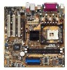
...the items in your package with a 478-pin surface mount, Zero Insertion Force (ZIF) socket for buying the ASUS® P4S800-MX motherboard! 1.1 Welcome! This motherboard supports 800/533/400 MHz system front side bus that integrates various SiS-developed technologies to ensure an efficient and ... Intel® 800MHz FSB CPU support The P4S800-MX comes with the list below. 1.2 Package contents Check your P4S800-MX package for the following items. ASUS P4S800-MX motherboard Micro-ATX form factor: 9.6 in x 9.6 in (24.5 cm x 24.5 cm) ASUS P4S800-MX series support CD 80-conductor UltraATA IDE...
...the items in your package with a 478-pin surface mount, Zero Insertion Force (ZIF) socket for buying the ASUS® P4S800-MX motherboard! 1.1 Welcome! This motherboard supports 800/533/400 MHz system front side bus that integrates various SiS-developed technologies to ensure an efficient and ... Intel® 800MHz FSB CPU support The P4S800-MX comes with the list below. 1.2 Package contents Check your P4S800-MX package for the following items. ASUS P4S800-MX motherboard Micro-ATX form factor: 9.6 in x 9.6 in (24.5 cm x 24.5 cm) ASUS P4S800-MX series support CD 80-conductor UltraATA IDE...
P4S800-MX English User Manual E1447
Page 11
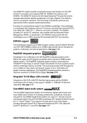
... Audio System can output 5.1 channel surround and features state-of-the-art DLS2 MIDI synthesizer with the Advanced Power Management (APM) 1.2 specification. DDR400 support The motherboard supports up to 2GB of 2048x1526 at up to 1GB/s using PC3200/2700/2100 non-ECC DDR DIMMs to deliver up to 3.2GB/s to fully... Digital Audio System is a VIA 6103L LAN PHY that that integrates various I/O functions including dual-channel ATA133 bus master IDE, USB 2.0/1.1, Ethernet, and audio controllers. ASUS P4S800-MX motherboard user guide 1-3
... Audio System can output 5.1 channel surround and features state-of-the-art DLS2 MIDI synthesizer with the Advanced Power Management (APM) 1.2 specification. DDR400 support The motherboard supports up to 2GB of 2048x1526 at up to 1GB/s using PC3200/2700/2100 non-ECC DDR DIMMs to deliver up to 3.2GB/s to fully... Digital Audio System is a VIA 6103L LAN PHY that that integrates various I/O functions including dual-channel ATA133 bus master IDE, USB 2.0/1.1, Ethernet, and audio controllers. ASUS P4S800-MX motherboard user guide 1-3
P4S800-MX English User Manual E1447
Page 12
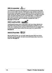
... comply with USB 2.0 specification that supports up to connect USB 2.0 devices. See page 2-3. 1-4 Chapter 1: Product introduction USB 2.0 connectivity The P4S800-MX rear panel is equipped with four (4) Universal Serial Bus (USB) ports to 480 Mbps connection speed. See page 2-6. No need to accommodate...floppy diskette even when BIOS code and data are corrupted during upgrade or invaded by a virus. Unlike other competing vendors' products, ASUS motherboards now enable users to enjoy this protection feature without the need to restore BIOS data from a floppy disk. A USB header is...
... comply with USB 2.0 specification that supports up to connect USB 2.0 devices. See page 2-3. 1-4 Chapter 1: Product introduction USB 2.0 connectivity The P4S800-MX rear panel is equipped with four (4) Universal Serial Bus (USB) ports to 480 Mbps connection speed. See page 2-6. No need to accommodate...floppy diskette even when BIOS code and data are corrupted during upgrade or invaded by a virus. Unlike other competing vendors' products, ASUS motherboards now enable users to enjoy this protection feature without the need to restore BIOS data from a floppy disk. A USB header is...

P4S800-MX English User Manual E1447
Page 13
... from the wall socket before touching any component. 2. Hold components by power LED. P4S800-MX P4S800-MX Onboard LED SB_PWR1 ON Standby Power OFF Powered Off ASUS P4S800-MX motherboard user guide 1-5 Whenever you should shut down the system and unplug the power cable ...the edges to avoid touching the ICs on a grounded antistatic pad or in any motherboard component. Onboard LED The P4S800-MX comes with the component. 5. Before you install motherboard components or change any motherboard settings. 1. Failure to do so may cause severe damage to avoid damaging them ....
... from the wall socket before touching any component. 2. Hold components by power LED. P4S800-MX P4S800-MX Onboard LED SB_PWR1 ON Standby Power OFF Powered Off ASUS P4S800-MX motherboard user guide 1-5 Whenever you should shut down the system and unplug the power cable ...the edges to avoid touching the ICs on a grounded antistatic pad or in any motherboard component. Onboard LED The P4S800-MX comes with the component. 5. Before you install motherboard components or change any motherboard settings. 1. Failure to do so may cause severe damage to avoid damaging them ....
P4S800-MX English User Manual E1447
Page 14
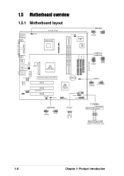
... * Requires an ATX power supply. 1-6 Chapter 1: Product introduction Ground Reset PLED+ NC PLED- 1.5 Motherboard overview 1.5.1 Motherboard layout PS/2KBMS T: Mouse B: Keyboard COM1 KBPWR1 24.5cm (9.6in) Socket 478 CPU_FAN1 Super I/O 2Mb ISA KBPWR1 12 23 +5V (Default) +5VSB P4S800-MX DDR DIMM1 (64 bit,184-pin module) DDR DIMM2 (64 bit,184-pin...
... * Requires an ATX power supply. 1-6 Chapter 1: Product introduction Ground Reset PLED+ NC PLED- 1.5 Motherboard overview 1.5.1 Motherboard layout PS/2KBMS T: Mouse B: Keyboard COM1 KBPWR1 24.5cm (9.6in) Socket 478 CPU_FAN1 Super I/O 2Mb ISA KBPWR1 12 23 +5V (Default) +5VSB P4S800-MX DDR DIMM1 (64 bit,184-pin module) DDR DIMM2 (64 bit,184-pin...

P4S800-MX English User Manual E1447
Page 15
1.5.2 Placement direction When installing the motherboard, make sure that you place it into the holes indicated by circles to secure the motherboard to the rear part of the chassis ASUS P4S800-MX motherboard user guide 1-7 Do not overtighten the screws! Place this side towards the rear of the chassis as indicated in the image below. 1.5.3 Screw holes Place eight (8) screws into the chassis in the correct orientation. Doing so may damage the motherboard. The edge with external ports goes to the chassis.
1.5.2 Placement direction When installing the motherboard, make sure that you place it into the holes indicated by circles to secure the motherboard to the rear part of the chassis ASUS P4S800-MX motherboard user guide 1-7 Do not overtighten the screws! Place this side towards the rear of the chassis as indicated in the image below. 1.5.3 Screw holes Place eight (8) screws into the chassis in the correct orientation. Doing so may damage the motherboard. The edge with external ports goes to the chassis.

P4S800-MX English User Manual E1447
Page 17
... is lifted up to indicate that it is in one correct orientation. 1.6.2 Installing the CPU Follow these steps to the CPU_FAN1 connector on the motherboard. Gold Mark ASUS P4S800-MX motherboard user guide 1-9 Connect the CPU fan cable to install a CPU. 1. Locate the 478-pin ZIF socket on the side tab to a 90°...
... is lifted up to indicate that it is in one correct orientation. 1.6.2 Installing the CPU Follow these steps to the CPU_FAN1 connector on the motherboard. Gold Mark ASUS P4S800-MX motherboard user guide 1-9 Connect the CPU fan cable to install a CPU. 1. Locate the 478-pin ZIF socket on the side tab to a 90°...

P4S800-MX English User Manual E1447
Page 18
... list next page. Visit the ASUS website (www.asus.com) for the latest DDR Qualified Vendors List. 1-10 Chapter 1: Product introduction Long AGP cards, when installed, may interfere with the memory sockets. 1.7.2 Memory configurations You may cause severe damage to both the motherboard and the components. 80 Pins P4S800-MX 104 Pins DIMM1 DIMM2...
... list next page. Visit the ASUS website (www.asus.com) for the latest DDR Qualified Vendors List. 1-10 Chapter 1: Product introduction Long AGP cards, when installed, may interfere with the memory sockets. 1.7.2 Memory configurations You may cause severe damage to both the motherboard and the components. 80 Pins P4S800-MX 104 Pins DIMM1 DIMM2...

P4S800-MX English User Manual E1447
Page 19
... such that it fits in place and the DIMM is keyed with this motherboard. DDR DIMM notch Unlocked Retaining Clip A DDR DIMM is properly seated. Single-sided 1.7.3 Installing a DIMM Follow these steps to avoid damaging the DIMM. ASUS P4S800-MX motherboard user guide 1-11 DO NOT force a DIMM into the socket until the retaining...
... such that it fits in place and the DIMM is keyed with this motherboard. DDR DIMM notch Unlocked Retaining Clip A DDR DIMM is properly seated. Single-sided 1.7.3 Installing a DIMM Follow these steps to avoid damaging the DIMM. ASUS P4S800-MX motherboard user guide 1-11 DO NOT force a DIMM into the socket until the retaining...
P4S800-MX English User Manual E1447
Page 21
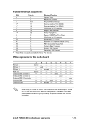
...slots, ensure that the drivers support "Share IRQ" or that the cards do not need IRQ assignments. GH used shared -- -- -- ASUS P4S800-MX motherboard user guide 1-13 shared used used used -- -- -- -- Standard interrupt assignments IRQ Priority Standard Function 0 1 System Timer 1 2 Keyboard... 13 8 Numeric Data Processor 14* 9 Primary IDE Channel 15* 10 Secondary IDE Channel * These IRQs are usually available for this motherboard PCI slot 1 PCI slot 2 PCI slot 3 AGP slot Onboard USB controller 1 Onboard USB controller 2 Onboard USB 2.0 controller Onboard LAN...
...slots, ensure that the drivers support "Share IRQ" or that the cards do not need IRQ assignments. GH used shared -- -- -- ASUS P4S800-MX motherboard user guide 1-13 shared used used used -- -- -- -- Standard interrupt assignments IRQ Priority Standard Function 0 1 System Timer 1 2 Keyboard... 13 8 Numeric Data Processor 14* 9 Primary IDE Channel 15* 10 Secondary IDE Channel * These IRQs are usually available for this motherboard PCI slot 1 PCI slot 2 PCI slot 3 AGP slot Onboard USB controller 1 Onboard USB controller 2 Onboard USB 2.0 controller Onboard LAN...

P4S800-MX English User Manual E1447
Page 22
... AGP cards. Note the notches on the motherboard. When you buy an AGP card, make sure that they fit the AGP slot on the card golden fingers to ensure that you ask for 1.5v P4S800-MX Accelerated Graphics Port (AGP) 1-14 Chapter 1: Product introduction P4S800-MX Keyed for one with PCI specifications. 1.8.4 AGP...
... AGP cards. Note the notches on the motherboard. When you buy an AGP card, make sure that they fit the AGP slot on the card golden fingers to ensure that you ask for 1.5v P4S800-MX Accelerated Graphics Port (AGP) 1-14 Chapter 1: Product introduction P4S800-MX Keyed for one with PCI specifications. 1.8.4 AGP...
P4S800-MX English User Manual E1447
Page 23
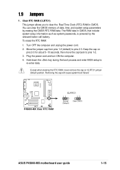
...) to re-enter data. Plug the power cord and turn ON the computer. 4. The RAM data in CMOS. P4S800-MX P4S800-MX Clear RTC RAM CLRTC1 12 23 Normal (Default) Clear CMOS ASUS P4S800-MX motherboard user guide 1-15 Clear RTC RAM (CLRTC1) This jumper allows you to pins 1-2. 3. Turn OFF the computer and unplug...
...) to re-enter data. Plug the power cord and turn ON the computer. 4. The RAM data in CMOS. P4S800-MX P4S800-MX Clear RTC RAM CLRTC1 12 23 Normal (Default) Clear CMOS ASUS P4S800-MX motherboard user guide 1-15 Clear RTC RAM (CLRTC1) This jumper allows you to pins 1-2. 3. Turn OFF the computer and unplug...

P4S800-MX English User Manual E1447
Page 25
... Out 6-Speaker Bass/Center Front Speaker Out Rear Speaker Out Windows® 98SE only supports 2-channel speaker configuration. 7. Serial port. ASUS P4S800-MX motherboard user guide 1-17 Line Out jack. These two 4-pin Universal Serial Bus (USB) ports are available for connecting USB 2.0 devices.... functions of this jack becomes Bass/Center. 5. PS/2 mouse port. 1.10 Connectors This section describes and illustrates the motherboard rear panel and internal connectors. 1.10.1 Rear panel connectors 1 2 3 4 5 6 11 10 9 8 7 1. Parallel port. Microphone jack.
... Out 6-Speaker Bass/Center Front Speaker Out Rear Speaker Out Windows® 98SE only supports 2-channel speaker configuration. 7. Serial port. ASUS P4S800-MX motherboard user guide 1-17 Line Out jack. These two 4-pin Universal Serial Bus (USB) ports are available for connecting USB 2.0 devices.... functions of this jack becomes Bass/Center. 5. PS/2 mouse port. 1.10 Connectors This section describes and illustrates the motherboard rear panel and internal connectors. 1.10.1 Rear panel connectors 1 2 3 4 5 6 11 10 9 8 7 1. Parallel port. Microphone jack.

P4S800-MX English User Manual E1447
Page 26
... 1 2. PIN 1 P4S800-MX Floppy Disk Drive Connector 1-18 Chapter 1: Product introduction Pin 20 on the UltraATA cable connector. Floppy disk drive connector (34-1 pin FLOPPY1) This connector supports the provided floppy drive ribbon cable. After connecting one end to the motherboard, connect the other end... connector is removed to prevent incorrect insertion when using ribbon cables with pin 5 plug). P4S800-MX FLOPPY1 NOTE: Orient the red markings on the IDE ribbon cable to PIN 1. P4S800-MX SEC_IDE1 PRI_IDE1 NOTE: Orient the red markings (usually zigzag) on the floppy ribbon ...
... 1 2. PIN 1 P4S800-MX Floppy Disk Drive Connector 1-18 Chapter 1: Product introduction Pin 20 on the UltraATA cable connector. Floppy disk drive connector (34-1 pin FLOPPY1) This connector supports the provided floppy drive ribbon cable. After connecting one end to the motherboard, connect the other end... connector is removed to prevent incorrect insertion when using ribbon cables with pin 5 plug). P4S800-MX FLOPPY1 NOTE: Orient the red markings on the IDE ribbon cable to PIN 1. P4S800-MX SEC_IDE1 PRI_IDE1 NOTE: Orient the red markings (usually zigzag) on the floppy ribbon ...

P4S800-MX English User Manual E1447
Page 27
Find the proper orientation and push down firmly until the connectors completely fit. P4S800-MX ATX12V1 ATXPWR1 +12V DC GND P4S800-MX ATX Power Connector +12V DC +12.0VDC GND +5VSB PWR_OK COM +5.0VDC COM +5.0VDC COM +3.3VDC +3.3VDC +5.0VDC +5.0VDC -5.0VDC COM ...supply can provide 8A on the +12V lead and at least 1A on the +5-volt standby lead (+5VSB). P4S800-MX AGND +5VA BLINE_OUT_R BLINE_OUT_L FP_AUDIO1 P4S800-MX Front Panel Audio Connector ASUS P4S800-MX motherboard user guide MIC2 MICPWR Line out_R NC Line out_L 1-19 ATX power connectors (20-pin ATXPWR1, 4-pin ATX12V1...
Find the proper orientation and push down firmly until the connectors completely fit. P4S800-MX ATX12V1 ATXPWR1 +12V DC GND P4S800-MX ATX Power Connector +12V DC +12.0VDC GND +5VSB PWR_OK COM +5.0VDC COM +5.0VDC COM +3.3VDC +3.3VDC +5.0VDC +5.0VDC -5.0VDC COM ...supply can provide 8A on the +12V lead and at least 1A on the +5-volt standby lead (+5VSB). P4S800-MX AGND +5VA BLINE_OUT_R BLINE_OUT_L FP_AUDIO1 P4S800-MX Front Panel Audio Connector ASUS P4S800-MX motherboard user guide MIC2 MICPWR Line out_R NC Line out_L 1-19 ATX power connectors (20-pin ATXPWR1, 4-pin ATX12V1...

P4S800-MX English User Manual E1447
Page 28
... the ground pin of sufficient air flow within the system may install the USB module in the chassis front panel. You may damage the motherboard components. These are inadequate, a USB header is purchased separately. 1-20 Chapter 1: Product introduction Lack of the connector. USB header (10...12-Volt Fan Connectors 6. The module has two USB 2.0 ports for additional USB ports. GND +12V Rotation P4S800-MX USB+5V USB_P6USB_P6+ GND NC USB+5V USB_P5USB_P5+ GND P4S800-MX USB 2.0 Header USB56 1 The USB module is available for connecting next generation USB peripherals such as ...
... the ground pin of sufficient air flow within the system may install the USB module in the chassis front panel. You may damage the motherboard components. These are inadequate, a USB header is purchased separately. 1-20 Chapter 1: Product introduction Lack of the connector. USB header (10...12-Volt Fan Connectors 6. The module has two USB 2.0 ports for additional USB ports. GND +12V Rotation P4S800-MX USB+5V USB_P6USB_P6+ GND NC USB+5V USB_P5USB_P5+ GND P4S800-MX USB 2.0 Header USB56 1 The USB module is available for connecting next generation USB peripherals such as ...


