A7V600-X User's manual
Page 17
Visit the ASUS website (www.asus.com) for 3D graphical applications. 8 Serial ATA connectors. The power supply ... the connector is a standby power on the +5V standby lead (+5VSB). 6 Floppy disk connector. ASUS A7V600-X Motherboard 1-7 This connector accommodates the provided ribbon cable for Serial ATA devices. 9 South bridge controller. This 2Mb... firmware contains the programmable BIOS program. 11 Standby power LED. Both the primary (blue) and secondary (black) connectors are slotted ...
Visit the ASUS website (www.asus.com) for 3D graphical applications. 8 Serial ATA connectors. The power supply ... the connector is a standby power on the +5V standby lead (+5VSB). 6 Floppy disk connector. ASUS A7V600-X Motherboard 1-7 This connector accommodates the provided ribbon cable for Serial ATA devices. 9 South bridge controller. This 2Mb... firmware contains the programmable BIOS program. 11 Standby power LED. Both the primary (blue) and secondary (black) connectors are slotted ...
A7V600-X User's manual
Page 42
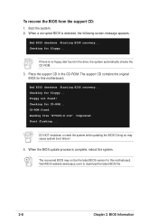
... floppy... Checking for floppy... Floppy not found . Reading file "A7V600-X.rom". Bad BIOS checksum. Starting BIOS recovery... The support CD contains the original BIOS for this motherboard. Visit ASUS website (www.asus.com) to download the latest BIOS file. 2-8 Chapter 2: BIOS Information Start flashing... The recovered BIOS may cause system boot failure! 4. If there is no floppy disk found...
... floppy... Checking for floppy... Floppy not found . Reading file "A7V600-X.rom". Bad BIOS checksum. Starting BIOS recovery... The support CD contains the original BIOS for this motherboard. Visit ASUS website (www.asus.com) to download the latest BIOS file. 2-8 Chapter 2: BIOS Information Start flashing... The recovered BIOS may cause system boot failure! 4. If there is no floppy disk found...


