
User Manual
Page 4
Table of contents 4.1.3 ASUS CrashFree BIOS 4-4 4.2 BIOS setup program 4-5 4.2.1 BIOS menu screen 4-6 4.2.2 Menu bar 4-6 4.2.3 Navigation keys 4-7 4.2.4 Menu items 4-7 4.2.5 Submenu items 4-7 4.2.6 Configuration fields 4-7 4.2.7 Pop-up window 4-7 4.2.8 Scroll bar 4-7 4.2.9 General help 4-7 4.3 Main menu 4-8 4.3.1 System Time 4-8 4.3.2 System Date 4-8 4.3.3 SATA 1-6 4-8 4.3.4 Storage Configuration 4-9 4.3.5 System Information 4-10 4.4 Advanced menu 4-11 4.4.1 CPU Configuration 4-11 4.4.2 Chipset 4-12 4.4.3 Onboard Devices Configuration 4-13...
Table of contents 4.1.3 ASUS CrashFree BIOS 4-4 4.2 BIOS setup program 4-5 4.2.1 BIOS menu screen 4-6 4.2.2 Menu bar 4-6 4.2.3 Navigation keys 4-7 4.2.4 Menu items 4-7 4.2.5 Submenu items 4-7 4.2.6 Configuration fields 4-7 4.2.7 Pop-up window 4-7 4.2.8 Scroll bar 4-7 4.2.9 General help 4-7 4.3 Main menu 4-8 4.3.1 System Time 4-8 4.3.2 System Date 4-8 4.3.3 SATA 1-6 4-8 4.3.4 Storage Configuration 4-9 4.3.5 System Information 4-10 4.4 Advanced menu 4-11 4.4.1 CPU Configuration 4-11 4.4.2 Chipset 4-12 4.4.3 Onboard Devices Configuration 4-13...
User Manual
Page 17
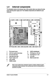
... view of the system when you disassemble or assemble the system. Power supply unit 6. DIMM sockets 8. PCI Express x1 slot 11. PCI slots 12. ASUS motherboard 9. ASUS V7-series P5G43M 1-7 PCI Express x16 slot 10. Metal bracket lock Refer to the bundled Quick Installation Guide for your reference. 5 6 7 8 10 9 P5QPL-VM EPU 12 11... assistance from professionals when you remove the side cover and the power supply unit. Front panel cover 2. 5.25-inch optical drive bays 3. 3.5-inch drive bay 4. CPU socket 7.
... view of the system when you disassemble or assemble the system. Power supply unit 6. DIMM sockets 8. PCI Express x1 slot 11. PCI slots 12. ASUS motherboard 9. ASUS V7-series P5G43M 1-7 PCI Express x16 slot 10. Metal bracket lock Refer to the bundled Quick Installation Guide for your reference. 5 6 7 8 10 9 P5QPL-VM EPU 12 11... assistance from professionals when you remove the side cover and the power supply unit. Front panel cover 2. 5.25-inch optical drive bays 3. 3.5-inch drive bay 4. CPU socket 7.

User Manual
Page 34
... Chapter 2: Starting up My Favorites My Favorites allows you need. To add an application: 1. AI Probe AI Probe automatically detects and displays the motherboard and CPU temperatures, CPU fan speed, and the voltage output.
... Chapter 2: Starting up My Favorites My Favorites allows you need. To add an application: 1. AI Probe AI Probe automatically detects and displays the motherboard and CPU temperatures, CPU fan speed, and the voltage output.

User Manual
Page 35
Information Click the tab on the Support window to go to see the detailed information about your system, motherboard, CPU, BIOS, installed device(s), and memory. Support Click any links on the Information window to the ASUS website, technical support website, download support website, or contact information. ASUS V7-series P5G43M 2-13
Information Click the tab on the Support window to go to see the detailed information about your system, motherboard, CPU, BIOS, installed device(s), and memory. Support Click any links on the Information window to the ASUS website, technical support website, download support website, or contact information. ASUS V7-series P5G43M 2-13

User Manual
Page 47
...move the cap back to clear the Real Time Clock (RTC) RAM in CMOS, which include system setup information such as system passwords. ASUS V7-series P5G43M 3-3 You must turn ON the computer. 4. Move the jumper cap from pins 1-2 (default) to overclocking. Shut down the key ...during the boot process and enter BIOS setup to overclocking, use the C.P.R. 3.3 Jumpers 1. Clear RTC RAM (3-pin CLRTC) This jumper allows you use the CPU Parameter ...
...move the cap back to clear the Real Time Clock (RTC) RAM in CMOS, which include system setup information such as system passwords. ASUS V7-series P5G43M 3-3 You must turn ON the computer. 4. Move the jumper cap from pins 1-2 (default) to overclocking. Shut down the key ...during the boot process and enter BIOS setup to overclocking, use the C.P.R. 3.3 Jumpers 1. Clear RTC RAM (3-pin CLRTC) This jumper allows you use the CPU Parameter ...

User Manual
Page 48
... the +5VSB lead, and a corresponding setting in reduced power mode). USB device wake-up (3-pin USBPW1-6, USBPW7-12) Set the jumpers to +5V to CPU, DRAM in slow refresh, power supply in the BIOS. 3-4 Chapter 3: Motherboard info Keyboard power (3-pin KBPWR) This jumper allows you can supply at least... on the keyboard (the default is for the internal USB connectors that you to enable or disable the keyboard wake-up from S1 sleep mode (CPU stopped, DRAM refreshed, system running in low power mode) using the connected USB devices. Set to +5VSB to additional USB ports. 3. This ...
... the +5VSB lead, and a corresponding setting in reduced power mode). USB device wake-up (3-pin USBPW1-6, USBPW7-12) Set the jumpers to +5V to CPU, DRAM in slow refresh, power supply in the BIOS. 3-4 Chapter 3: Motherboard info Keyboard power (3-pin KBPWR) This jumper allows you can supply at least... on the keyboard (the default is for the internal USB connectors that you to enable or disable the keyboard wake-up from S1 sleep mode (CPU stopped, DRAM refreshed, system running in low power mode) using the connected USB devices. Set to +5VSB to additional USB ports. 3. This ...
User Manual
Page 49
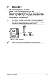
... of each cable matches the ground pin of 1 A~7 A (84 W max.) at +12V. ASUS V7-series P5G43M 3-5 Do not forget to connect the fan cables to the fan connectors on the fan connectors! 3.4 Connectors 1. Only the 4-pin CPU fan connector supports the ASUS Q-FAN feature. Insufficient air flow inside the system may damage the motherboard components...
... of each cable matches the ground pin of 1 A~7 A (84 W max.) at +12V. ASUS V7-series P5G43M 3-5 Do not forget to connect the fan cables to the fan connectors on the fan connectors! 3.4 Connectors 1. Only the 4-pin CPU fan connector supports the ASUS Q-FAN feature. Insufficient air flow inside the system may damage the motherboard components...

User Manual
Page 66
... options: [0] [5] [10] [15] [20] [25] [30] [35] 4.3.5 System Information This menu gives you an overview of the general system specifications. Processor Displays the auto-detected CPU specification. The BIOS automatically detects the items in driver. Configuration option: [Disabled] [Enabled] IDE Detect Time Out (Sec) [35] Selects the time out value for...
... options: [0] [5] [10] [15] [20] [25] [30] [35] 4.3.5 System Information This menu gives you an overview of the general system specifications. Processor Displays the auto-detected CPU specification. The BIOS automatically detects the items in driver. Configuration option: [Disabled] [Enabled] IDE Detect Time Out (Sec) [35] Selects the time out value for...

User Manual
Page 67
... Devices Configuration USB Configuration PCIPnP Adjust System frequency/voltage. 4.4.1 CPU Configuration The items in independent partitions. Take caution when changing the settings of the Advanced menu items. Incorrect field values can function as multiple virtual systems. Configuration options: [Enabled] [Disabled] ASUS V7-series P5G43M 4-11 Key in CMOS, then the actual and set in...
... Devices Configuration USB Configuration PCIPnP Adjust System frequency/voltage. 4.4.1 CPU Configuration The items in independent partitions. Take caution when changing the settings of the Advanced menu items. Incorrect field values can function as multiple virtual systems. Configuration options: [Enabled] [Disabled] ASUS V7-series P5G43M 4-11 Key in CMOS, then the actual and set in...

User Manual
Page 68
... Timing by SPD. Configuration options: [IGD] [PCI/IGD] [PCI/PEG] [PCG/IGD [PEG/PCI] 4-12 Chapter 4: BIOS setup CPU TM function [Enabled] Enables or disables Intel® CPU Thermal Monitor (TM) function, a CPU overheating protection function. Configuration options: [Disabled] [Enabled] Execute-Disable Bit Capability [Enabled] Allows you to enable or disable the...the submenu. Select an item then press to change the advanced chipset settings. Enable this item to [Disabled] if you installed an Intel® CPU that supports the Enhanced Intel® SpeedStep® Technology (EIST).
... Timing by SPD. Configuration options: [IGD] [PCI/IGD] [PCI/PEG] [PCG/IGD [PEG/PCI] 4-12 Chapter 4: BIOS setup CPU TM function [Enabled] Enables or disables Intel® CPU Thermal Monitor (TM) function, a CPU overheating protection function. Configuration options: [Disabled] [Enabled] Execute-Disable Bit Capability [Enabled] Allows you to enable or disable the...the submenu. Select an item then press to change the advanced chipset settings. Enable this item to [Disabled] if you installed an Intel® CPU that supports the Enhanced Intel® SpeedStep® Technology (EIST).
User Manual
Page 73
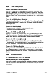
...disable RTC to generate a wake event. This feature requires an ATX power supply that provides at least 1A on the +5VSB lead. ASUS V7-series P5G43M 4-17 When set to display the detected temperatures. This feature requires an ATX power supply that provides at least 1A on the +5VSB...186;F] or [Ignored] MB Temperature [xxxºC/xxxºF] or [Ignored] The onboard hardware monitor automatically detects and displays the motherboard and CPU temperatures. This feature requires an ATX power supply that provides at least 1A on the +5VSB lead. Select Ignored if you to Enabled, ...
...disable RTC to generate a wake event. This feature requires an ATX power supply that provides at least 1A on the +5VSB lead. ASUS V7-series P5G43M 4-17 When set to display the detected temperatures. This feature requires an ATX power supply that provides at least 1A on the +5VSB...186;F] or [Ignored] MB Temperature [xxxºC/xxxºF] or [Ignored] The onboard hardware monitor automatically detects and displays the motherboard and CPU temperatures. This feature requires an ATX power supply that provides at least 1A on the +5VSB lead. Select Ignored if you to Enabled, ...

User Manual
Page 74
..., 12V Voltage [xxxV] or [Ignored] The onboard hardware monitor automatically detects the voltage output through the onboard voltage regulators. 4-18 Chapter 4: BIOS setup CPU Q-Fan Control [Disabled] Allows you do not wish to display the detected speed. CPU Fan Speed [xxxxRPM] or [Ignored] The onboard hardware monitor automatically detects and displays the...
..., 12V Voltage [xxxV] or [Ignored] The onboard hardware monitor automatically detects the voltage output through the onboard voltage regulators. 4-18 Chapter 4: BIOS setup CPU Q-Fan Control [Disabled] Allows you do not wish to display the detected speed. CPU Fan Speed [xxxxRPM] or [Ignored] The onboard hardware monitor automatically detects and displays the...


