Terminator A7VT400 User''s Manual for English
Page 10
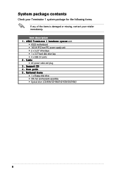
...e s y s t e m with • ASUS motherboard • 165 W PFC/non-PFC power supply unit • 2 x 5.25" drive bays • 1 x 3.5" hard disk drive bay • 4 x USB 2.0 ports 2. Cable • AC power cable and plug 3 . Support CD 4 . Optional... items • 1 x Floppy disk drive • CPU fan and heatsink assembly • Optical drive (CD-ROM/CD-RW/DVD-ROM/DVD-RW) x System package contents Check your Terminator...
...e s y s t e m with • ASUS motherboard • 165 W PFC/non-PFC power supply unit • 2 x 5.25" drive bays • 1 x 3.5" hard disk drive bay • 4 x USB 2.0 ports 2. Cable • AC power cable and plug 3 . Support CD 4 . Optional... items • 1 x Floppy disk drive • CPU fan and heatsink assembly • Optical drive (CD-ROM/CD-RW/DVD-ROM/DVD-RW) x System package contents Check your Terminator...
Terminator A7VT400 User''s Manual for English
Page 12
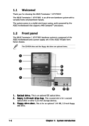
The system comes in a stylish mini-tower casing, and is powered by the ASUS motherboard that supports AMD Sempron™ processors. 1.2 Front panel The ASUS Terminator 1 A7VT400 barebone system is composed of the ASUS motherboard and a power supply unit in -one barebone system with a versatile home entertainment feature. O p t i c.... 1 2 4 3 5 6 7 8 9 10 1 . 1.1 Welcome! i n c h d r i v e b a y . This is for choosing the ASUS Terminator 1 A7VT400! This is an all-in the ASUS TriOptix form factor chassis. The ASUS Terminator 1 A7VT400 is an optional IDE optical drive. 2 .
The system comes in a stylish mini-tower casing, and is powered by the ASUS motherboard that supports AMD Sempron™ processors. 1.2 Front panel The ASUS Terminator 1 A7VT400 barebone system is composed of the ASUS motherboard and a power supply unit in -one barebone system with a versatile home entertainment feature. O p t i c.... 1 2 4 3 5 6 7 8 9 10 1 . 1.1 Welcome! i n c h d r i v e b a y . This is for choosing the ASUS Terminator 1 A7VT400! This is an all-in the ASUS TriOptix form factor chassis. The ASUS Terminator 1 A7VT400 is an optional IDE optical drive. 2 .
Terminator A7VT400 User''s Manual for English
Page 15
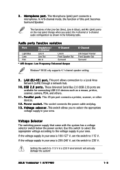
... l t a g e s e l e c t o r . Voltage Selector The switching power supply that came with the system has a voltage selector switch below the power socket. If the voltage supply in your area is 200-240 V, set the switch to the voltage supply in your area. In 4/6-channel mode, the function of the Line Out (lime), Line In (blue... Front Speaker Out Surround Windows® 98 SE only supports 4.1-channel speaker setting. 9 . Use this port becomes Surround Speaker. ASUS Terminator 1 A7VT400 1-5 P o w e r s o c k e t . Setting the switch to a Local Area Network (LAN) through...
... l t a g e s e l e c t o r . Voltage Selector The switching power supply that came with the system has a voltage selector switch below the power socket. If the voltage supply in your area is 200-240 V, set the switch to the voltage supply in your area. In 4/6-channel mode, the function of the Line Out (lime), Line In (blue... Front Speaker Out Surround Windows® 98 SE only supports 4.1-channel speaker setting. 9 . Use this port becomes Surround Speaker. ASUS Terminator 1 A7VT400 1-5 P o w e r s o c k e t . Setting the switch to a Local Area Network (LAN) through...
Terminator A7VT400 User''s Manual for English
Page 35
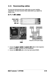
... Ground Reset Ground PANEL HDLED RESET SMI PWRBTN* * Requires an ATX power supply. • Connect the power switch and power LED cables to their respective leads in the PANEL connector on the motherboard. • Connect the H D D L E D cable to the 2-pin lead marked HDLED. You must reconnect these cables before you were installing components. ASUS Terminator 1 A7VT400 2-19
... Ground Reset Ground PANEL HDLED RESET SMI PWRBTN* * Requires an ATX power supply. • Connect the power switch and power LED cables to their respective leads in the PANEL connector on the motherboard. • Connect the H D D L E D cable to the 2-pin lead marked HDLED. You must reconnect these cables before you were installing components. ASUS Terminator 1 A7VT400 2-19
Terminator A7VT400 User''s Manual for English
Page 55
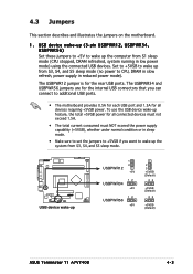
...5V 12 USBPWR34 +5V 12 USBPWR56 +5V 2 3 +5VSB (Default) 23 +5VSB (Default) 23 +5VSB (Default) ASUS Terminator T1 A7VT400 4-3 To use the USB device wake-up the computer from S3, S4, and S5 sleep mode (no power to additional USB ports. • The motherboard provides 0.5A for each USB port and 1.5A for...or in sleep mode. • Make sure to set the jumpers to +5VSB if you can connect to CPU, DRAM in slow refresh, power supply in low power mode) using the connected USB devices. 4.3 Jumpers This section describes and illustrates the jumpers on the motherboard. 1 . The USBPWR34 and USBPWR56...
...5V 12 USBPWR34 +5V 12 USBPWR56 +5V 2 3 +5VSB (Default) 23 +5VSB (Default) 23 +5VSB (Default) ASUS Terminator T1 A7VT400 4-3 To use the USB device wake-up the computer from S3, S4, and S5 sleep mode (no power to additional USB ports. • The motherboard provides 0.5A for each USB port and 1.5A for...or in sleep mode. • Make sure to set the jumpers to +5VSB if you can connect to CPU, DRAM in slow refresh, power supply in low power mode) using the connected USB devices. 4.3 Jumpers This section describes and illustrates the jumpers on the motherboard. 1 . The USBPWR34 and USBPWR56...
Terminator A7VT400 User''s Manual for English
Page 87
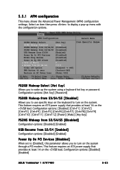
... +5VSB lead. This feature requires an ATX power supply that provides at least 1A on the system through a PCI modem. Configuration options: [Hot key] [Password] PS2KB Wakeup from S3/S4/S5 [Disabled] Allows you to turn on the +5VSB lead. Configuration options: [Disabled] [Enabled] ASUS Terminator 1 A7VT400 5-23 APM Configuration Select Menu PS2KB Wakeup Select...
... +5VSB lead. This feature requires an ATX power supply that provides at least 1A on the system through a PCI modem. Configuration options: [Hot key] [Password] PS2KB Wakeup from S3/S4/S5 [Disabled] Allows you to turn on the +5VSB lead. Configuration options: [Disabled] [Enabled] ASUS Terminator 1 A7VT400 5-23 APM Configuration Select Menu PS2KB Wakeup Select...


