User Manual
Page 1
R TX97-X Pentium® ATX Motherboard USER'S MANUAL
R TX97-X Pentium® ATX Motherboard USER'S MANUAL
User Manual
Page 4
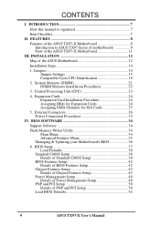
... Setup 48 PNP and PCI Setup 50 Details of the ASUS Motherboard 12 Installation Steps 14 1. INSTALLATION 12 Map of PNP and PCI Setup 50 Load BIOS Defaults 52 4 ASUS TX97-X User's Manual System Memory (DIMM 21 DIMM Memory Installation... Procedures 22 3. INTRODUCTION 7 How this manual is organized 7 Item Checklist 7 II. Central Processing Unit (CPU 23 4. FEATURES 8 Features of the ASUS TX97-X Motherboard 8 Introduction to ASUS TX97 Series of motherboards 9 Parts of the ASUS TX97-X Motherboard ...
... Setup 48 PNP and PCI Setup 50 Details of the ASUS Motherboard 12 Installation Steps 14 1. INSTALLATION 12 Map of PNP and PCI Setup 50 Load BIOS Defaults 52 4 ASUS TX97-X User's Manual System Memory (DIMM 21 DIMM Memory Installation... Procedures 22 3. INTRODUCTION 7 How this manual is organized 7 Item Checklist 7 II. Central Processing Unit (CPU 23 4. FEATURES 8 Features of the ASUS TX97-X Motherboard 8 Introduction to ASUS TX97 Series of motherboards 9 Parts of the ASUS TX97-X Motherboard ...
User Manual
Page 5
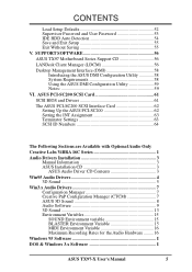
... DOS & Windows 3.x Software I ASUS TX97-X User's Manual 5 CONTENTS Load Setup Defaults 52 Supervisor Password and User Password 53 IDE HDD Auto Detection 54 Save and Exit Setup 55 Exit Without Saving 55 V. SUPPORT SOFTWARE 56 ASUS TX97 Motherboard Series Support CD 56 LANDesk Client Manager... (LDCM 56 Desktop Management Interface (DMI 58 Introducing the ASUS DMI Configuration Utility 58 System Requirements 58 Using the ASUS DMI Configuration Utility 59 Notes 59 VI...
... DOS & Windows 3.x Software I ASUS TX97-X User's Manual 5 CONTENTS Load Setup Defaults 52 Supervisor Password and User Password 53 IDE HDD Auto Detection 54 Save and Exit Setup 55 Exit Without Saving 55 V. SUPPORT SOFTWARE 56 ASUS TX97 Motherboard Series Support CD 56 LANDesk Client Manager... (LDCM 56 Desktop Management Interface (DMI 58 Introducing the ASUS DMI Configuration Utility 58 System Requirements 58 Using the ASUS DMI Configuration Utility 59 Notes 59 VI...
User Manual
Page 7
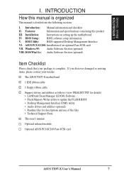
...III. VII. DOS/Win3.1x: Audio Software Section (optional) Item Checklist Please check that your retailer. √ The ASUS TX97-X motherboard √ 1 IDE ribbon cable √ 1 floppy ribbon cable √ Support drivers and utilities as follows (view ...software setup information. V. Installation: Instructions on setting up the motherboard. ASUS PCI-SC200: Installation of the files • Technical Support Form √ This user's manual Optional infrared module Optional ASUS PCI-SC200 Fast-SCSI card ASUS TX97-X User's Manual 7 I . DMI Utility: BIOS supported...
...III. VII. DOS/Win3.1x: Audio Software Section (optional) Item Checklist Please check that your retailer. √ The ASUS TX97-X motherboard √ 1 IDE ribbon cable √ 1 floppy ribbon cable √ Support drivers and utilities as follows (view ...software setup information. V. Installation: Instructions on setting up the motherboard. ASUS PCI-SC200: Installation of the files • Technical Support Form √ This user's manual Optional infrared module Optional ASUS PCI-SC200 Fast-SCSI card ASUS TX97-X User's Manual 7 I . DMI Utility: BIOS supported...
User Manual
Page 8
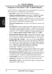
... compatible serial ports and one parallel port with 3D sound. • Optional IrDA Connector: This motherboard supports an optional infrared port module for wireless interface. 8 ASUS TX97-X User's Manual This controller supports PIO Modes 3 and 4 and Bus Master IDE DMA Mode... Interface (DMI): Supports DMI through BIOS which allows hardware to communicate within a standard protocol creating a higher level of the ASUS TX97-X Motherboard The ASUS TX97-X is available for wireless connections. Two floppy drives of hard drives, expansion cards, and other devices virtually automatic. •...
... compatible serial ports and one parallel port with 3D sound. • Optional IrDA Connector: This motherboard supports an optional infrared port module for wireless interface. 8 ASUS TX97-X User's Manual This controller supports PIO Modes 3 and 4 and Bus Master IDE DMA Mode... Interface (DMI): Supports DMI through BIOS which allows hardware to communicate within a standard protocol creating a higher level of the ASUS TX97-X Motherboard The ASUS TX97-X is available for wireless connections. Two floppy drives of hard drives, expansion cards, and other devices virtually automatic. •...
User Manual
Page 9
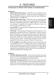
... more Energy Saving Features for its normal RPM range and alarm thresholds. • Temperature Monitoring and Alert - Both the BIOS and hardware levels of ASUS TX97 series of motherboards sup- Each fan can be used. • PC '97 Compliant - To prevent system overheat and system damage, there is a heat sensor under the CPU...
... more Energy Saving Features for its normal RPM range and alarm thresholds. • Temperature Monitoring and Alert - Both the BIOS and hardware levels of ASUS TX97 series of motherboards sup- Each fan can be used. • PC '97 Compliant - To prevent system overheat and system damage, there is a heat sensor under the CPU...
User Manual
Page 10
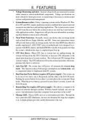
...95, Windows NT, and OS/2, require much more than 4 seconds places the system into Sleep mode. ASUS TX97 series of motherboards were designed to cooperate with BIOS, chipset, and flash EPROM to prevent possible application crashes. The system fans... one is Sleep mode and the other is pressed for more memory and hard drive space to critical motherboard components. System voltage levels are malfunctioning, the system will power off automatically even in one of system overheat... the Soft-Off mode. This allows a computer to the user. 10 ASUS TX97-X User's Manual II.
...95, Windows NT, and OS/2, require much more than 4 seconds places the system into Sleep mode. ASUS TX97 series of motherboards were designed to cooperate with BIOS, chipset, and flash EPROM to prevent possible application crashes. The system fans... one is Sleep mode and the other is pressed for more memory and hard drive space to critical motherboard components. System voltage levels are malfunctioning, the system will power off automatically even in one of system overheat... the Soft-Off mode. This allows a computer to the user. 10 ASUS TX97-X User's Manual II.
User Manual
Page 11
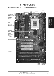
B: Serial Conn. II. FEATURES (Parts of the ASUS TX97-X Motherboard T: PS/2 Mouse B: PS/2 Keyboard T: USB Port 1 B: USB Port 2 CPU ZIF CPU Thermal 3 DIMM Sockets Socket 7 Sensor COM 1 T: Parallel Conn. FEATURES Parts of Board) II. COM 2 Intel's 430TX PCIset (Optional) T:Joystick/Midi B:1/8" Output/ Input/Mic 4 PCI Slots Floppy Drive Connector IDE 2 Connector IDE 1 Connector 512KB Pipelined Burst L2 Cache 4 ISA Slots Hardware Programmable Monitor Flash ROM ASUS TX97-X User's Manual 11
B: Serial Conn. II. FEATURES (Parts of the ASUS TX97-X Motherboard T: PS/2 Mouse B: PS/2 Keyboard T: USB Port 1 B: USB Port 2 CPU ZIF CPU Thermal 3 DIMM Sockets Socket 7 Sensor COM 1 T: Parallel Conn. FEATURES Parts of Board) II. COM 2 Intel's 430TX PCIset (Optional) T:Joystick/Midi B:1/8" Output/ Input/Mic 4 PCI Slots Floppy Drive Connector IDE 2 Connector IDE 1 Connector 512KB Pipelined Burst L2 Cache 4 ISA Slots Hardware Programmable Monitor Flash ROM ASUS TX97-X User's Manual 11

User Manual
Page 12
INSTALLATION (Map of the ASUS Motherboard COM 1 PS/2 Top: Mouse Bottom: Keyboard FANPWR3 12V USB Top: USB 1 Bottom: USB 2 Multi-I/O (En/Dis) SIO Board Power Input for BIOS Infrared Con. (IrDA) ISA Slot 4 Panel Connections IDE LED NOTE: The items in Outline are available only with the optional onboard Audio. 12 ASUS TX97-X User's Manual...
INSTALLATION (Map of the ASUS Motherboard COM 1 PS/2 Top: Mouse Bottom: Keyboard FANPWR3 12V USB Top: USB 1 Bottom: USB 2 Multi-I/O (En/Dis) SIO Board Power Input for BIOS Infrared Con. (IrDA) ISA Slot 4 Panel Connections IDE LED NOTE: The items in Outline are available only with the optional onboard Audio. 12 ASUS TX97-X User's Manual...

User Manual
Page 13
... Switch Lead (2-pins) p. 31 Reset Switch Lead (2-pins) p. 31 Keyboard Lock Switch Lead (5-pins) p. 31 Speaker Output Connector (4-pins) p. 32 Infrared Port Module Connector p. 32 Motherboard Power Connector (20-pin Block) ASUS TX97-X User's Manual 13
... Switch Lead (2-pins) p. 31 Reset Switch Lead (2-pins) p. 31 Keyboard Lock Switch Lead (5-pins) p. 31 Speaker Output Connector (4-pins) p. 32 Infrared Port Module Connector p. 32 Motherboard Power Connector (20-pin Block) ASUS TX97-X User's Manual 13
User Manual
Page 14
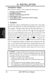
...with two pins will be shown as [----], [1-2], [2-3] for our motherboards is written besides pin 1 on the bag that both jumpers be sharing pins from other components against damage from the system. 14 ASUS TX97-X User's Manual WARNING: Computer motheboards and components contain very delicate...or on jumpers with two jumper numbers require that came with the keyboard connector away from yourself. tions of the Motherboard" on the Motherboard 2. Install the Central Processing Unit (CPU) 4. Jumpers Several hardware settings are separated from static electricity, you ...
...with two pins will be shown as [----], [1-2], [2-3] for our motherboards is written besides pin 1 on the bag that both jumpers be sharing pins from other components against damage from the system. 14 ASUS TX97-X User's Manual WARNING: Computer motheboards and components contain very delicate...or on jumpers with two jumper numbers require that came with the keyboard connector away from yourself. tions of the Motherboard" on the Motherboard 2. Install the Central Processing Unit (CPU) 4. Jumpers Several hardware settings are separated from static electricity, you ...
User Manual
Page 17
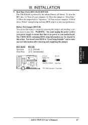
... that there is powered by this jumper and attaching a current meter to your motherboard. Battery Test Jumper (RTCLR) You can test the battery's current by removing this action. WARNING: You must unplug the power cord to pins 1&2. INSTALLATION (Jumpers) ASUS TX97-X User's Manual 17 The CMOS RAM containing BIOS setup information may be...
... that there is powered by this jumper and attaching a current meter to your motherboard. Battery Test Jumper (RTCLR) You can test the battery's current by removing this action. WARNING: You must unplug the power cord to pins 1&2. INSTALLATION (Jumpers) ASUS TX97-X User's Manual 17 The CMOS RAM containing BIOS setup information may be...

User Manual
Page 18
...Ratio (BF0, BF1) These jumpers set together with the Cyrix 166+ installed on this motherboard. 18 ASUS TX97-X User's Manual These must be set the frequency ratio between the Internal frequency of the ... [2-3] [1-2] [2-3] [1-2] [2-3] [1-2] [1-2] [1-2] [1-2] [1-2] [1-2] [1-2] [1-2] [1-2] [1-2] [1-2] [1-2] [1-2] [1-2] [1-2] [1-2] [1-2] [2-3] *NOTE: Only Cyrix Revision 2.7 or later is supported on this motherboard. See next page for revision identification. INSTALLATION (Jumpers) III. INSTALLATION 6. CPU to the CPU. These allow the selection of the CPU's External frequency (or BUS...
...Ratio (BF0, BF1) These jumpers set together with the Cyrix 166+ installed on this motherboard. 18 ASUS TX97-X User's Manual These must be set the frequency ratio between the Internal frequency of the ... [2-3] [1-2] [2-3] [1-2] [2-3] [1-2] [1-2] [1-2] [1-2] [1-2] [1-2] [1-2] [1-2] [1-2] [1-2] [1-2] [1-2] [1-2] [1-2] [1-2] [1-2] [1-2] [2-3] *NOTE: Only Cyrix Revision 2.7 or later is supported on this motherboard. See next page for revision identification. INSTALLATION (Jumpers) III. INSTALLATION 6. CPU to the CPU. These allow the selection of the CPU's External frequency (or BUS...

User Manual
Page 19
... VID1 VID2 1 2 3 2.5Volt 1 2 3 2.7Volt 1 2 3 2.8Volt 1 2 3 2.9Volt VID0 VID1 VID2 VID0 VID1 VID2 VID0 VID1 VID2 1 1 2 2 3 3 3.1Volt 3.4Volt Voltage Regulator Output Selection 1 2 3 3.5Volt R ASUS TX97-X User's Manual 19 Look on this motherboard is labeled Cyrix 6x86 P166+ but must be Revision 2.7 and later. III. INSTALLATION Compatible Cyrix CPU Identification The only Cyrix CPU that...
... VID1 VID2 1 2 3 2.5Volt 1 2 3 2.7Volt 1 2 3 2.8Volt 1 2 3 2.9Volt VID0 VID1 VID2 VID0 VID1 VID2 VID0 VID1 VID2 1 1 2 2 3 3 3.1Volt 3.4Volt Voltage Regulator Output Selection 1 2 3 3.5Volt R ASUS TX97-X User's Manual 19 Look on this motherboard is labeled Cyrix 6x86 P166+ but must be Revision 2.7 and later. III. INSTALLATION Compatible Cyrix CPU Identification The only Cyrix CPU that...
User Manual
Page 21
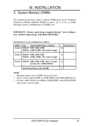
..., or 32, 64, or 128MB. Slot 3 must be empty Total Memory x1 Socket 2 SDRAM 8MB, 16MB, 32MB x1 SDRAM 64MB, 128MB - System Memory (DIMM) This motherboard has three sockets to support 3.3Volt (power level) Unbuffered Synchronous DRAMs (SDRAM) DIMMs of the BIOS SOFTWARE. III. Slot 1 or 2 must x1 not have 64... 8MB, 16MB, 32MB SDRAM 64MB, 128MB - INSTALLATION 2. Slot 3 must be empty Socket 3 SDRAM 8MB, 16MB, 32MB - Maximum memory of DIMMs must be 256MB or less. ASUS TX97-X User's Manual 21
..., or 32, 64, or 128MB. Slot 3 must be empty Total Memory x1 Socket 2 SDRAM 8MB, 16MB, 32MB x1 SDRAM 64MB, 128MB - System Memory (DIMM) This motherboard has three sockets to support 3.3Volt (power level) Unbuffered Synchronous DRAMs (SDRAM) DIMMs of the BIOS SOFTWARE. III. Slot 1 or 2 must x1 not have 64... 8MB, 16MB, 32MB SDRAM 64MB, 128MB - INSTALLATION 2. Slot 3 must be empty Socket 3 SDRAM 8MB, 16MB, 32MB - Maximum memory of DIMMs must be 256MB or less. ASUS TX97-X User's Manual 21
User Manual
Page 22
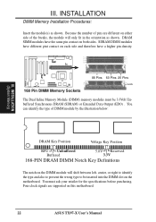
...pin contact on the DIMM module will only fit in the orientation as shown. You must be inserted into the DIMM slot on this motherboard. 22 ASUS TX97-X User's Manual Four clock signals are different on either side of DIMM module by the illustration below: R III. You can identify ... notch on both sides. INSTALLATION DIMM Memory Installation Procedures: Insert the module(s) as shown. Because the number of pins are supported on the motherboard. III. DRAM SIMM modules have a higher pin density. 168 Pin DIMM Memory Sockets 88 Pins 60 Pins 20 Pins Lock The Dual Inline...
...pin contact on the DIMM module will only fit in the orientation as shown. You must be inserted into the DIMM slot on this motherboard. 22 ASUS TX97-X User's Manual Four clock signals are different on either side of DIMM module by the illustration below: R III. You can identify ... notch on both sides. INSTALLATION DIMM Memory Installation Procedures: Insert the module(s) as shown. Because the number of pins are supported on the motherboard. III. DRAM SIMM modules have a higher pin density. 168 Pin DIMM Memory Sockets 88 Pins 60 Pins 20 Pins Lock The Dual Inline...
User Manual
Page 23
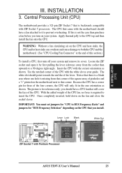
...Unit (CPU) The motherboard provides a 321-pin ZIF Socket 7 that will only fit in the one hole is required to the CPU top and then install the fan onto the CPU. WARNING: Without a fan circulating air on the CPU that corner. Insert the CPU with Pentium Processor ASUS TX97-X User's Manual ... of the CPU fan, no force is missing from the socket then upwards to prevent overheating. With the added weight of the CPU with the motherboard should point towards the end the of pin holes and a "1" printed on your guide. III. INSTALLATION 3. Once completely inserted, hold down on ...
...Unit (CPU) The motherboard provides a 321-pin ZIF Socket 7 that will only fit in the one hole is required to the CPU top and then install the fan onto the CPU. WARNING: Without a fan circulating air on the CPU that corner. Insert the CPU with Pentium Processor ASUS TX97-X User's Manual ... of the CPU fan, no force is missing from the socket then upwards to prevent overheating. With the added weight of the CPU with the motherboard should point towards the end the of pin holes and a "1" printed on your guide. III. INSTALLATION 3. Once completely inserted, hold down on ...
User Manual
Page 24
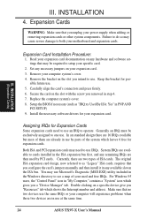
... and press firmly. 6. Setup the BIOS if necessary (such as "Legacy" ISA cards, requires that may cause severe damage to setup your motherboard and expansion cards. Assigning IRQs for expansion cards. Generally an IRQ must be required to both your specific card. 2. System IRQs are already ... Expansion Cards WARNING: Make sure that no two devices use . 5. Both ISA and PCI expansion cards may use at the same time. 24 ASUS TX97-X User's Manual The original ISA expansion card design, now referred to use by PCI cards. Remove your expansion card. Keep the bracket for your...
... and press firmly. 6. Setup the BIOS if necessary (such as "Legacy" ISA cards, requires that may cause severe damage to setup your motherboard and expansion cards. Assigning IRQs for expansion cards. Generally an IRQ must be required to both your specific card. 2. System IRQs are already ... Expansion Cards WARNING: Make sure that no two devices use . 5. Both ISA and PCI expansion cards may use at the same time. 24 ASUS TX97-X User's Manual The original ISA expansion card design, now referred to use by PCI cards. Remove your expansion card. Keep the bracket for your...
User Manual
Page 25
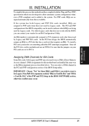
... for this motherboard are assigned automatically from those used by Legacy and PNP ISA cards. To install a PCI card, you need to INT A. You can contact your PCI cards are assigned to set to use an INTA #, be used by Legacy cards. INSTALLATION (D(CMoAnCnhecatnonrsel)s) ASUS TX97-X User's ...PNP configuration section of the BIOS setup utility can be sure that the jumpers on this motherboard has complied with the BIOS, you wish to the system. INSTALLATION To simplify this process this motherboard use a DMA (Direct Memory Access) channel. For PNP cards, IRQs are handled ...
... for this motherboard are assigned automatically from those used by Legacy and PNP ISA cards. To install a PCI card, you need to INT A. You can contact your PCI cards are assigned to set to use an INTA #, be used by Legacy cards. INSTALLATION (D(CMoAnCnhecatnonrsel)s) ASUS TX97-X User's ...PNP configuration section of the BIOS setup utility can be sure that the jumpers on this motherboard has complied with the BIOS, you wish to the system. INSTALLATION To simplify this process this motherboard use a DMA (Direct Memory Access) channel. For PNP cards, IRQs are handled ...
User Manual
Page 26
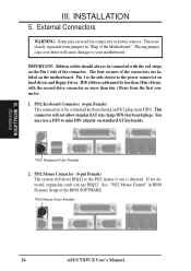
...) 26 ASUS TX97-X User's Manual Pin 1 is the side closest to the PS/2 mouse if one is for connectors or power sources. IDE ribbon cable must be connected with the second drive connector no more than 6in. (15cm) from jumpers in BIOS Features Setup of the Motherboard." If... not detected, expansion cards can use a DIN to your motherboard. INSTALLATION 5. Placing jumper caps over these will not allow standard AT size (large DIN) keyboard plugs. PS...
...) 26 ASUS TX97-X User's Manual Pin 1 is the side closest to the PS/2 mouse if one is for connectors or power sources. IDE ribbon cable must be connected with the second drive connector no more than 6in. (15cm) from jumpers in BIOS Features Setup of the Motherboard." If... not detected, expansion cards can use a DIN to your motherboard. INSTALLATION 5. Placing jumper caps over these will not allow standard AT size (large DIN) keyboard plugs. PS...


