User Manual
Page 5
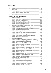
...5.1.2 Installing hard disk drives 5-2 5.1.3 Setting the RAID item in BIOS 5-2 5.1.4 RAID configuration utilities 5-3 5.2 LSI Logic Embedded SATA RAID Setup Utility 5-4 5.2.1 Creating a RAID set 5-5 5.2.2 Adding or viewing a RAID configuration 5-11 5.2.3 Initializing the logical drives 5-14 5.2.4 Rebuilding failed drives 5-19 5.2.5 Checking the drives for data consistency 5-21 5.2.6 Deleting a RAID configuration 5-24 5.2.7 Selecting the boot drive from a RAID set 5-25 5.2.8 Enabling the WriteCache 5-26 5.3 Global Array Manager 5-26 5.4 Adaptec SCSISelect(TM) Utility (NCLV-DS2 model...
...5.1.2 Installing hard disk drives 5-2 5.1.3 Setting the RAID item in BIOS 5-2 5.1.4 RAID configuration utilities 5-3 5.2 LSI Logic Embedded SATA RAID Setup Utility 5-4 5.2.1 Creating a RAID set 5-5 5.2.2 Adding or viewing a RAID configuration 5-11 5.2.3 Initializing the logical drives 5-14 5.2.4 Rebuilding failed drives 5-19 5.2.5 Checking the drives for data consistency 5-21 5.2.6 Deleting a RAID configuration 5-24 5.2.7 Selecting the boot drive from a RAID set 5-25 5.2.8 Enabling the WriteCache 5-26 5.3 Global Array Manager 5-26 5.4 Adaptec SCSISelect(TM) Utility (NCLV-DS2 model...
User Manual
Page 9
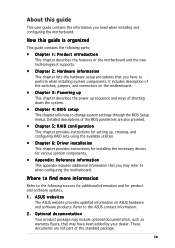
...; Chapter 4: BIOS setup This chapter tells how to change system settings through the BIOS Setup menus. It includes description of the switches, jumpers, and connectors on ASUS hardware and software products. Detailed descriptions of the BIOS parameters are not part of the motherboard and the new technologies it supports. • Chapter 2: Hardware information This chapter lists the hardware setup procedures that may have to the ASUS contact information. 2. Optional documentation Your product...
...; Chapter 4: BIOS setup This chapter tells how to change system settings through the BIOS Setup menus. It includes description of the switches, jumpers, and connectors on ASUS hardware and software products. Detailed descriptions of the BIOS parameters are not part of the motherboard and the new technologies it supports. • Chapter 2: Hardware information This chapter lists the hardware setup procedures that may have to the ASUS contact information. 2. Optional documentation Your product...
User Manual
Page 12
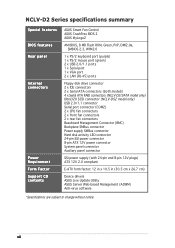
...-D2/SATA model only) Ultra320 SCSI connector (NCLV-DS2 model only) USB 2.0/1.1 connector Serial port connector (COM2) 2 x CPU fan connectors 2 x front fan connectors 2 x rear fan connectors Baseboard Management Connector (BMC) Backplane SMBus connector Power supply SMBus connector Hard disk activity LED connector 24-pin SSI power connector 8-pin ATX 12V power connector System panel connector Auxiliary panel connector SSI power supply (with 24-pin and 8-pin 12V plugs) ATX 12V 2.0 compliant E-ATX form factor: 12 in x 10.5 in (30.5 cm x 26.7 cm) Device drivers ASUS Live Update Utility ASUS Server...
...-D2/SATA model only) Ultra320 SCSI connector (NCLV-DS2 model only) USB 2.0/1.1 connector Serial port connector (COM2) 2 x CPU fan connectors 2 x front fan connectors 2 x rear fan connectors Baseboard Management Connector (BMC) Backplane SMBus connector Power supply SMBus connector Hard disk activity LED connector 24-pin SSI power connector 8-pin ATX 12V power connector System panel connector Auxiliary panel connector SSI power supply (with 24-pin and 8-pin 12V plugs) ATX 12V 2.0 compliant E-ATX form factor: 12 in x 10.5 in (30.5 cm x 26.7 cm) Device drivers ASUS Live Update Utility ASUS Server...
User Manual
Page 16
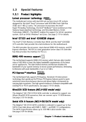
... the latest server applications. This high speed interface is onboard to support one 68-pin Ultra320 SCSI connector, that provides the interface for details. Serial ATA II feature (NCLV-D2/SATA model only) The Adaptec® AIC-8130 SATA controller is a new generation server class I/O controller hub that can connect up to meet the higher bandwidth requirements of up to four SATA II hard disk drives with RAID 0, RAID 1, and RAID 10 configurations. Intel...
... the latest server applications. This high speed interface is onboard to support one 68-pin Ultra320 SCSI connector, that provides the interface for details. Serial ATA II feature (NCLV-D2/SATA model only) The Adaptec® AIC-8130 SATA controller is a new generation server class I/O controller hub that can connect up to meet the higher bandwidth requirements of up to four SATA II hard disk drives with RAID 0, RAID 1, and RAID 10 configurations. Intel...

User Manual
Page 17
... details. The ASIC monitors the voltage levels to create all types of current for details. See pages 2-28 and 5-4 for details. The onboard Broadcom® BCM5721 and BCM5705E Gigabit LAN controllers use the PCI Express and PCI interfaces, respectively, and have network throughput close to 150 MB/s data transfer rate. USB 2.0 technology The motherboard implements the Universal Serial Bus (USB) 2.0 specification, dramatically increasing the connection speed from the 12...
... details. The ASIC monitors the voltage levels to create all types of current for details. See pages 2-28 and 5-4 for details. The onboard Broadcom® BCM5721 and BCM5705E Gigabit LAN controllers use the PCI Express and PCI interfaces, respectively, and have network throughput close to 150 MB/s data transfer rate. USB 2.0 technology The motherboard implements the Universal Serial Bus (USB) 2.0 specification, dramatically increasing the connection speed from the 12...
User Manual
Page 18
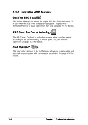
... ASUS Smart Fan Control technology smartly adjusts the fan speeds according to the system loading to buy a replacement ROM chip. 1.3.2 Innovative ASUS features CrashFree BIOS 2 This feature allows you to personalize and add style to your system with customizable boot logos. ASUS MyLogo2™ This new feature present in the motherboard allows you to restore the original BIOS data from the support CD in case when the BIOS codes and data...
... ASUS Smart Fan Control technology smartly adjusts the fan speeds according to the system loading to buy a replacement ROM chip. 1.3.2 Innovative ASUS features CrashFree BIOS 2 This feature allows you to personalize and add style to your system with customizable boot logos. ASUS MyLogo2™ This new feature present in the motherboard allows you to restore the original BIOS data from the support CD in case when the BIOS codes and data...
User Manual
Page 37
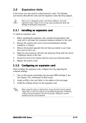
.... Replace the system cover. 2.5.2 Configuring an expansion card After installing the expansion card, configure the it and make the necessary hardware settings for information on the slot. 5. Remove the system unit cover (if your motherboard is completely seated on BIOS setup. 2. Align the card connector with it by adjusting the software settings. 1. Turn on the next page. 3. Keep the screw for the expansion card. Before installing the expansion card, read the documentation that they support. See Chapter 4 for the card. 2. 2.5 Expansion slots...
.... Replace the system cover. 2.5.2 Configuring an expansion card After installing the expansion card, configure the it and make the necessary hardware settings for information on the slot. 5. Remove the system unit cover (if your motherboard is completely seated on BIOS setup. 2. Align the card connector with it by adjusting the software settings. 1. Turn on the next page. 3. Keep the screw for the expansion card. Before installing the expansion card, read the documentation that they support. See Chapter 4 for the card. 2. 2.5 Expansion slots...

User Manual
Page 47
... disk drive connector 2 . Pin 5 on the connector is for the jumper settings. • Pin 20 on the IDE connector is removed to match the covered hole on the IDE ribbon cable to PIN 1. NCLV-D2 Series IDE connectors ASUS NCLV-D2 Series 2-27 Floppy disk drive connector (34-1 pin FLOPPY) This connector is removed to the hard disk documentation for the provided floppy disk drive (FDD) signal cable. Refer to prevent incorrect cable connection when using...
... disk drive connector 2 . Pin 5 on the connector is for the jumper settings. • Pin 20 on the IDE connector is removed to match the covered hole on the IDE ribbon cable to PIN 1. NCLV-D2 Series IDE connectors ASUS NCLV-D2 Series 2-27 Floppy disk drive connector (34-1 pin FLOPPY) This connector is removed to the hard disk documentation for the provided floppy disk drive (FDD) signal cable. Refer to prevent incorrect cable connection when using...
User Manual
Page 77
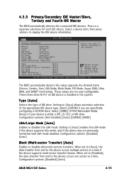
... not user-configurable. These values are specifically configuring a CD-ROM drive. Configuration options: [Disabled] [Auto] Block (Multi-sector Transfer) [Auto] Enables or disables data multi-sectors transfers. 4.3.5 Primary/Secondary IDE Master/Slave, Tertiary and Fourth IDE Master The BIOS automatically detects the connected IDE devices. Select [ARMD] (ATAPI Removable Media Device) if your device is installed in the system. Type [Auto] Selects the type of device connected to display the IDE device information. Configuration options: [Disabled] [Auto] ASUS...
... not user-configurable. These values are specifically configuring a CD-ROM drive. Configuration options: [Disabled] [Auto] Block (Multi-sector Transfer) [Auto] Enables or disables data multi-sectors transfers. 4.3.5 Primary/Secondary IDE Master/Slave, Tertiary and Fourth IDE Master The BIOS automatically detects the connected IDE devices. Select [ARMD] (ATAPI Removable Media Device) if your device is installed in the system. Type [Auto] Selects the type of device connected to display the IDE device information. Configuration options: [Disabled] [Auto] ASUS...
User Manual
Page 78
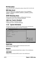
... number of the general system specifications. Configuration options: [Disabled] [Enabled] 4.3.6 System Information This menu gives you an overview of the motherboard. ASUS BIOS Displays the auto-detected BIOS version in this menu. The BIOS automatically detects the items in the motherboard. 4-16 Chapter 4: BIOS setup Main System Information BIOS SETUP UTILITY Model Name ASUS NCLV-D2/SATA Model ID 8001A0 ASUS-BIOS Version Date 1001.003 03/16/2005 Processor System Memory Select Screen Select Item +- Model Name Displays the auto-detected ASUS motherboard model...
... number of the general system specifications. Configuration options: [Disabled] [Enabled] 4.3.6 System Information This menu gives you an overview of the motherboard. ASUS BIOS Displays the auto-detected BIOS version in this menu. The BIOS automatically detects the items in the motherboard. 4-16 Chapter 4: BIOS setup Main System Information BIOS SETUP UTILITY Model Name ASUS NCLV-D2/SATA Model ID 8001A0 ASUS-BIOS Version Date 1001.003 03/16/2005 Processor System Memory Select Screen Select Item +- Model Name Displays the auto-detected ASUS motherboard model...
User Manual
Page 85
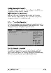
... +- When set to RSDT pointer list. Configuration options: [Disabled] [Enabled] ASUS NCLV-D2 Series 4-23 IMPORTANT!!! Advanced Power Configuration ACPI APIC Support APM Configuration BIOS SETUP UTILITY [Enabled] Include ACPI APIC table pointer to [Reserved], the IRQ is reserved for use PCI bus mastering when reading/writing to IDE devices. Configuration options: [Disabled] [Enabled] IRQ-xx assigned to [PCI Device] When set to display the configuration options. otherwise, a system boot failure may occur. When set to [PCI Device], the specific IRQ is...
... +- When set to RSDT pointer list. Configuration options: [Disabled] [Enabled] ASUS NCLV-D2 Series 4-23 IMPORTANT!!! Advanced Power Configuration ACPI APIC Support APM Configuration BIOS SETUP UTILITY [Enabled] Include ACPI APIC table pointer to [Reserved], the IRQ is reserved for use PCI bus mastering when reading/writing to IDE devices. Configuration options: [Disabled] [Enabled] IRQ-xx assigned to [PCI Device] When set to display the configuration options. otherwise, a system boot failure may occur. When set to [PCI Device], the specific IRQ is...

User Manual
Page 88
...). Configuration options: [Disabled] [2 USB Ports] [All USB Ports] Legacy USB Support [Auto] Allows you to set the USB 2.0 controller mode to enable or disable support for legacy USB devices. Select an item then press to change the USB-related features. Advanced USB Configuration Module Version - 2.23.2-7.4 USB Devices Enabled: None USB Function Legacy USB Support USB 2.0 Controller USB 2.0 Controller Mode BIOS SETUP UTILITY [All USB Ports] [Auto] [Enabled] [HiSpeed] Enables USB host controllers. 4.4.5 USB Configuration The items in this menu allows you to display the configuration...
...). Configuration options: [Disabled] [2 USB Ports] [All USB Ports] Legacy USB Support [Auto] Allows you to set the USB 2.0 controller mode to enable or disable support for legacy USB devices. Select an item then press to change the USB-related features. Advanced USB Configuration Module Version - 2.23.2-7.4 USB Devices Enabled: None USB Function Legacy USB Support USB 2.0 Controller USB 2.0 Controller Mode BIOS SETUP UTILITY [All USB Ports] [Auto] [Enabled] [HiSpeed] Enables USB host controllers. 4.4.5 USB Configuration The items in this menu allows you to display the configuration...
User Manual
Page 90
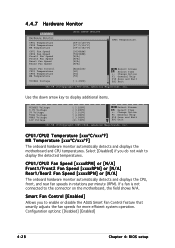
... motherboard and CPU temperatures. Select [Disabled] if you to display additional items. VCORE2 Voltage 3.3V Voltage 5V Voltage 5VSB Voltage VBAT Voltage 12V Voltage [ 1.258V] [ 3.280V] [ 5.010V] [ 4.980V] [ 3.088V] [11.749V] Select Screen Select Item +- Configuration options: [Disabled] [Enabled] 4-28 Chapter 4: BIOS setup Change Option F1 General Help F10 Save and Exit ESC Exit v02.58 (C)Copyright 1985-2004, American Megatrends, Inc. If a fan is not connected to display the detected temperatures. 4.4.7 Hardware Monitor...
... motherboard and CPU temperatures. Select [Disabled] if you to display additional items. VCORE2 Voltage 3.3V Voltage 5V Voltage 5VSB Voltage VBAT Voltage 12V Voltage [ 1.258V] [ 3.280V] [ 5.010V] [ 4.980V] [ 3.088V] [11.749V] Select Screen Select Item +- Configuration options: [Disabled] [Enabled] 4-28 Chapter 4: BIOS setup Change Option F1 General Help F10 Save and Exit ESC Exit v02.58 (C)Copyright 1985-2004, American Megatrends, Inc. If a fan is not connected to display the detected temperatures. 4.4.7 Hardware Monitor...
User Manual
Page 93
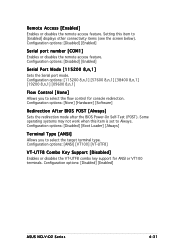
... key support for console redirection. Configuration options: [Disabled] [Enabled] ASUS NCLV-D2 Series 4-31 Configuration options: [Disabled] [Enabled] Serial port number [COM1] Enables or disables the remote access feature. Remote Access [Enabled] Enables or disables the remote access feature. Some operating systems may not work when this item to Always. Configuration options: [None] [Hardware] [Software] Redirection After BIOS POST [Always] Sets the redirection mode after the BIOS Power-On Self-Test (POST). Setting this item is set to [Enabled] displays other connectivity...
... key support for console redirection. Configuration options: [Disabled] [Enabled] ASUS NCLV-D2 Series 4-31 Configuration options: [Disabled] [Enabled] Serial port number [COM1] Enables or disables the remote access feature. Remote Access [Enabled] Enables or disables the remote access feature. Some operating systems may not work when this item to Always. Configuration options: [None] [Hardware] [Software] Redirection After BIOS POST [Always] Sets the redirection mode after the BIOS Power-On Self-Test (POST). Setting this item is set to [Enabled] displays other connectivity...
User Manual
Page 94
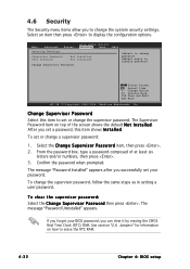
... BIOS password, you successfully set or change password. The message "Password Installed" appears after you can clear it by erasing the CMOS Real Time Clock (RTC) RAM. From the password box, type a password composed of the screen shows the default N o t I n s t a l l e d. Select an item then press to disable password. Main Advanced Server Security Settings BIOS SETUP UTILITY Security Boot Supervisor Password : Not Installed User Password : Not Installed Change Supervisor Password Exit to erase the RTC RAM. 4-32 Chapter 4: BIOS setup Select the Change...
... BIOS password, you successfully set or change password. The message "Password Installed" appears after you can clear it by erasing the CMOS Real Time Clock (RTC) RAM. From the password box, type a password composed of the screen shows the default N o t I n s t a l l e d. Select an item then press to disable password. Main Advanced Server Security Settings BIOS SETUP UTILITY Security Boot Supervisor Password : Not Installed User Password : Not Installed Change Supervisor Password Exit to erase the RTC RAM. 4-32 Chapter 4: BIOS setup Select the Change...
User Manual
Page 95
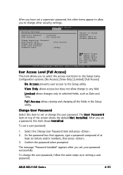
...shows the default N o t I n s t a l l e d. After you to change password. To change to change other items appear to allow change the user password, follow the same steps as Date and Time. L i m i t e d allows changes only to disable password. Main Advanced Server BIOS SETUP UTILITY Security Boot Exit Security Settings Supervisor Password : Installed User Password : Not Installed Change Supervisor Password User Access Level Change User Password Clear User Password Password Check [Full Access] [Setup] to any field. To set or change the user password. ASUS NCLV-D2...
...shows the default N o t I n s t a l l e d. After you to change password. To change to change other items appear to allow change the user password, follow the same steps as Date and Time. L i m i t e d allows changes only to disable password. Main Advanced Server BIOS SETUP UTILITY Security Boot Exit Security Settings Supervisor Password : Installed User Password : Not Installed Change Supervisor Password User Access Level Change User Password Clear User Password Password Check [Full Access] [Setup] to any field. To set or change the user password. ASUS NCLV-D2...
User Manual
Page 98
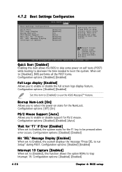
...' If Error [Enabled] When set to Enabled, the system displays the message "Press DEL to trap Interrupt 19. When set to [Enabled], this function allows the option ROMs to run Setup" during POST. Configuration options: [Disabled] [Enabled] Interrupt 19 Capture [Enabled] When set to [Disabled], BIOS performs all the POST items. Configuration options: [Disabled] [Enabled] Full Logo display [Enabled] Allows you to select the power-on self tests (POST) while booting to decrease the time needed to use the ASUS MyLogo2...
...' If Error [Enabled] When set to Enabled, the system displays the message "Press DEL to trap Interrupt 19. When set to [Enabled], this function allows the option ROMs to run Setup" during POST. Configuration options: [Disabled] [Enabled] Interrupt 19 Capture [Enabled] When set to [Disabled], BIOS performs all the POST items. Configuration options: [Disabled] [Enabled] Full Logo display [Enabled] Allows you to select the power-on self tests (POST) while booting to decrease the time needed to use the ASUS MyLogo2...
User Manual
Page 103
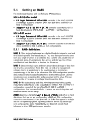
... RAID 0+1 configuration you get all applications to the surviving drive as a RAID set. 5.1 Setting up RAID The motherboard comes with the following RAID solutions: NCLV-D2/SATA model • LSI Logic Embedded SATA RAID controller in the Intel® 6300ESB Southbridge supports up to two SATA hard disk drives and RAID 0 or RAID 1 configuration. • A d a p t e c® AIC-7901X PCI-X SCSI controller supports SCSI hard disk drives and RAID 0, RAID 1, and RAID 0+1 configurations. 5.1.1 RAID definitions R A I D 0 + 1 is required for this setup. This RAID configuration provides data...
... RAID 0+1 configuration you get all applications to the surviving drive as a RAID set. 5.1 Setting up RAID The motherboard comes with the following RAID solutions: NCLV-D2/SATA model • LSI Logic Embedded SATA RAID controller in the Intel® 6300ESB Southbridge supports up to two SATA hard disk drives and RAID 0 or RAID 1 configuration. • A d a p t e c® AIC-7901X PCI-X SCSI controller supports SCSI hard disk drives and RAID 0, RAID 1, and RAID 0+1 configurations. 5.1.1 RAID definitions R A I D 0 + 1 is required for this setup. This RAID configuration provides data...
User Manual
Page 104
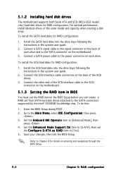
... Mode], then press . 4. To install the SCSI hard disks for RAID configuration. Set the E n h a n c e d M o d e S u p p o r t O n item to [S-ATA], then set from SATA hard disk drives attached to the power connector on the motherboard. 5.1.3 Setting the RAID item in BIOS You must set the RAID item in the system user guide. 2. To install the SATA hard disks for details on the motherboard. 3. Connect a SATA power cable to the SATA connectors supported by the Intel® 6300ESB Southbridge chip. To do this: 1. Save your changes, then exit the BIOS Setup. Connect a SATA signal...
... Mode], then press . 4. To install the SCSI hard disks for RAID configuration. Set the E n h a n c e d M o d e S u p p o r t O n item to [S-ATA], then set from SATA hard disk drives attached to the power connector on the motherboard. 5.1.3 Setting the RAID item in BIOS You must set the RAID item in the system user guide. 2. To install the SATA hard disks for details on the motherboard. 3. Connect a SATA power cable to the SATA connectors supported by the Intel® 6300ESB Southbridge chip. To do this: 1. Save your changes, then exit the BIOS Setup. Connect a SATA signal...
User Manual
Page 173
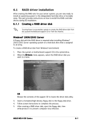
... disk to locate the driver disk utility. 3. ASUS NCLV-D2 Series 6-1 After creating a RAID driver disk, eject the floppy disk, then write-protect it to complete the process. 5. Place the system or motherboard support CD in the optical drive. 2. Follow screen instructions to prevent computer virus infection. This part provides instructions on a hard disk drive that is required when installing Windows® 2000/2003 Server operating system on how to install the RAID controller drivers during OS installation. 6.1.1 Creating a RAID driver disk...
... disk to locate the driver disk utility. 3. ASUS NCLV-D2 Series 6-1 After creating a RAID driver disk, eject the floppy disk, then write-protect it to complete the process. 5. Place the system or motherboard support CD in the optical drive. 2. Follow screen instructions to prevent computer virus infection. This part provides instructions on a hard disk drive that is required when installing Windows® 2000/2003 Server operating system on how to install the RAID controller drivers during OS installation. 6.1.1 Creating a RAID driver disk...


