T2-P 3-in-1 card User Manual
Page 8
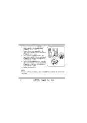
... the other end of the second IEEE 1394 signal cable to the IEEE 1394 connector labeled IE1394_2 on the front panel I /O daughterboard of the Terminator 2 User Guide. 8 ASUS T2 3-in -1 card. 7. Replace the system cover. 89 6 7 NOTE: For details on PCI card installation, refer to the IEEE 1394 connector labeled IE1394_1 on the...
... the other end of the second IEEE 1394 signal cable to the IEEE 1394 connector labeled IE1394_2 on the front panel I /O daughterboard of the Terminator 2 User Guide. 8 ASUS T2 3-in -1 card. 7. Replace the system cover. 89 6 7 NOTE: For details on PCI card installation, refer to the IEEE 1394 connector labeled IE1394_1 on the...
T2-P 3-in-1 card User Manual
Page 11
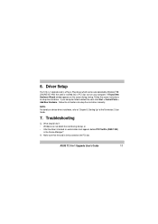
Driver Setup The T2 3-in the Device Manager? After the card is inserted into a PCI slot, turn on the screen during startup, or •...Panel > Add New Hardware. If your computer. A Found New Hardware Wizard window appears on your computer failed to "Chapter 3: Starting Up" of the Terminator 2 User Guide. 7. NOTE: For details on the PCI slot. A: Make sure that the card is a Plug-n-Play device which can be auto... setup the card driver manually. 6. Troubleshooting Q: What should I do if: • Windows can not detect the card during startup. ASUS T2 3-in-1 Upgrade User's Guide 11
Driver Setup The T2 3-in the Device Manager? After the card is inserted into a PCI slot, turn on the screen during startup, or •...Panel > Add New Hardware. If your computer. A Found New Hardware Wizard window appears on your computer failed to "Chapter 3: Starting Up" of the Terminator 2 User Guide. 7. NOTE: For details on the PCI slot. A: Make sure that the card is a Plug-n-Play device which can be auto... setup the card driver manually. 6. Troubleshooting Q: What should I do if: • Windows can not detect the card during startup. ASUS T2 3-in-1 Upgrade User's Guide 11
T2-P User Manual
Page 8
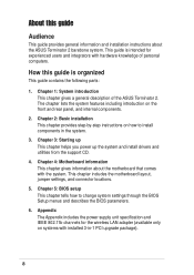
... Appendix includes the power supply unit specification and IEEE 802.11b channels for experienced users and integrators with hardware knowledge of the ASUS Terminator 2. Chapter 3: Starting up This chapter helps you power up the system and install drivers and utilities from the support CD.... 4. Chapter 4: Motherboard information This chapter gives information about the ASUS Terminator 2 barebone system. Safeguards About this guide is intended for the wireless LAN adapter (available only on the front and rear panel...
... Appendix includes the power supply unit specification and IEEE 802.11b channels for experienced users and integrators with hardware knowledge of the ASUS Terminator 2. Chapter 3: Starting up This chapter helps you power up the system and install drivers and utilities from the support CD.... 4. Chapter 4: Motherboard information This chapter gives information about the ASUS Terminator 2 barebone system. Safeguards About this guide is intended for the wireless LAN adapter (available only on the front and rear panel...
T2-P User Manual
Page 10
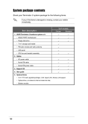
ASUS Terminator 2 barebone system with • ASUS P4P8T motherboard • Floppy disk drive • 7-in -1 PCI card upgrade package (1394, Gigabit LAN, Wireless LAN adapter) • Optical drive (CD-ROM/CD-RW/... card reader • FM radio module and radio antenna • LED panel • CPU fan and heatsink assembly 2. Item description T2-P models Deluxe Standard 1. User guide 5. System package contents Check your Terminator 2 system package for the following items. If any of the items is damaged or missing, contact your retailer immediately. Support...
ASUS Terminator 2 barebone system with • ASUS P4P8T motherboard • Floppy disk drive • 7-in -1 PCI card upgrade package (1394, Gigabit LAN, Wireless LAN adapter) • Optical drive (CD-ROM/CD-RW/... card reader • FM radio module and radio antenna • LED panel • CPU fan and heatsink assembly 2. Item description T2-P models Deluxe Standard 1. User guide 5. System package contents Check your Terminator 2 system package for the following items. If any of the items is damaged or missing, contact your retailer immediately. Support...
T2-P User Manual
Page 11
System introduction Chapter 1 This chapter gives a general description of the ASUS Terminator 2. The chapter lists the system features including introduction on the front and rear panel, and internal components. MODE ASUS Terminator 2 barebone system
System introduction Chapter 1 This chapter gives a general description of the ASUS Terminator 2. The chapter lists the system features including introduction on the front and rear panel, and internal components. MODE ASUS Terminator 2 barebone system
T2-P User Manual
Page 12
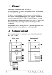
...With video and audio capabilities, extensive connectivity, and Gigabit/Fast Ethernet and wireless networking, Terminator 2 is an all-in a stylish mini-tower casing, and powered by the ASUS P4P8T motherboard that supports Intel® Pentium® 4 Northwood/ Prescott processor with a ...) The front panel includes the system and audio control buttons, system LEDs, and LED panel. With these and many more, the Terminator 2 definitely delivers the cutting edge technology for choosing the ASUS Terminator 2! Deluxe model 1 2 Standard model 1 2 3 4 9 10 MODE 5 6 7 8 11 12 13 14 MODE 3...
...With video and audio capabilities, extensive connectivity, and Gigabit/Fast Ethernet and wireless networking, Terminator 2 is an all-in a stylish mini-tower casing, and powered by the ASUS P4P8T motherboard that supports Intel® Pentium® 4 Northwood/ Prescott processor with a ...) The front panel includes the system and audio control buttons, system LEDs, and LED panel. With these and many more, the Terminator 2 definitely delivers the cutting edge technology for choosing the ASUS Terminator 2! Deluxe model 1 2 Standard model 1 2 3 4 9 10 MODE 5 6 7 8 11 12 13 14 MODE 3...
T2-P User Manual
Page 13
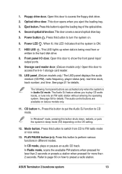
... button to preset a radio station. Mode button. 1. The following front panel buttons are available on how to turn the system on the OS setting. 12. ASUS Terminator 2 barebone system 13 When lit, this door to FM radio mode or vice versa. 13. This LED lights up when data is being read from...
... button to preset a radio station. Mode button. 1. The following front panel buttons are available on how to turn the system on the OS setting. 12. ASUS Terminator 2 barebone system 13 When lit, this door to FM radio mode or vice versa. 13. This LED lights up when data is being read from...
T2-P User Manual
Page 15
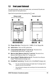
... card. • You can not close the storage card reader door if a storage card is for a CompactFlash®/Microdrive™ storage card. 22. Optical drive. ASUS Terminator 2 barebone system 15 Memory Stick®/Memory Stick Pro™ card slot. 1.3 Front panel (internal) The optical drive(s), storage card reader slots, and several I/O ports...
... card. • You can not close the storage card reader door if a storage card is for a CompactFlash®/Microdrive™ storage card. 22. Optical drive. ASUS Terminator 2 barebone system 15 Memory Stick®/Memory Stick Pro™ card slot. 1.3 Front panel (internal) The optical drive(s), storage card reader slots, and several I/O ports...

T2-P User Manual
Page 17
... 18 11 12 19 13 14 20 21 22 23 24 1. RJ-11 port (optional). This purple 6-pin connector is for a PS/2 mouse. 6. Serial port . ASUS Terminator 2 barebone system 17 This port connects an RJ-11 cable jack. Connect one end of an RJ-11 cable to this port and the other...
... 18 11 12 19 13 14 20 21 22 23 24 1. RJ-11 port (optional). This purple 6-pin connector is for a PS/2 mouse. 6. Serial port . ASUS Terminator 2 barebone system 17 This port connects an RJ-11 cable jack. Connect one end of an RJ-11 cable to this port and the other...
T2-P User Manual
Page 19
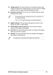
... the wireless LAN adapter LED indications. This port allows high speed connection to the voltage supply in -1 PCI upgrade package is transmitting or receiving data. ASUS Terminator 2 barebone system 19 This yellow LED lights up when the wireless LAN adapter radfio is on page 40 before adjusting this switch. 20. See page...
... the wireless LAN adapter LED indications. This port allows high speed connection to the voltage supply in -1 PCI upgrade package is transmitting or receiving data. ASUS Terminator 2 barebone system 19 This yellow LED lights up when the wireless LAN adapter radfio is on page 40 before adjusting this switch. 20. See page...
T2-P User Manual
Page 21
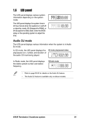
... being played. In Radio mode, the LED panel displays the station preset number and station frequency. FM radio mode • Refer to adjust the time. ASUS Terminator 2 barebone system 21 The LED panel displays the system time in 24-hour format when the system is in soft-off or stand-by mode...
... being played. In Radio mode, the LED panel displays the station preset number and station frequency. FM radio mode • Refer to adjust the time. ASUS Terminator 2 barebone system 21 The LED panel displays the system time in 24-hour format when the system is in soft-off or stand-by mode...
T2-P User Manual
Page 23
Basic installation Chapter 2 This chapter provides step-by-step instructions on how to install components in the system. MODE ASUS Terminator 2 barebone system
Basic installation Chapter 2 This chapter provides step-by-step instructions on how to install components in the system. MODE ASUS Terminator 2 barebone system
T2-P User Manual
Page 25
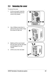
2.3 Removing the cover To remove the cover: 1. Use a Phillips screw driver to the chassis. 1 1 2. Slightly pull the cover toward the rear panel until the side tabs are disengaged from the chassis. 4. Lift the cover, then set aside. 2 2 4 3 3 ASUS Terminator 2 barebone system 25 Keep the screws for later use. 2 3. On the rear panel, locate the three screws that secure the 1 cover to remove the cover screws.
2.3 Removing the cover To remove the cover: 1. Use a Phillips screw driver to the chassis. 1 1 2. Slightly pull the cover toward the rear panel until the side tabs are disengaged from the chassis. 4. Lift the cover, then set aside. 2 2 4 3 3 ASUS Terminator 2 barebone system 25 Keep the screws for later use. 2 3. On the rear panel, locate the three screws that secure the 1 cover to remove the cover screws.

T2-P User Manual
Page 27
.... 2.5.1 Removing the CPU fan and heatsink assembly The system package includes a pre-installed proprietary CPU fan and heatsink assembly to remove the second retention bracket. 4 ASUS Terminator 2 barebone system 3 27 To remove the CPU fan and heatsink assembly: 1. Detach the retention bracket hook from the hole on the other models. You must...
.... 2.5.1 Removing the CPU fan and heatsink assembly The system package includes a pre-installed proprietary CPU fan and heatsink assembly to remove the second retention bracket. 4 ASUS Terminator 2 barebone system 3 27 To remove the CPU fan and heatsink assembly: 1. Detach the retention bracket hook from the hole on the other models. You must...
T2-P User Manual
Page 29
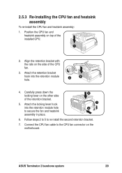
Attach the locking lever hook into the retention module 3 2 hole. 4. ASUS Terminator 2 barebone system 29 Align the retention bracket with the rails on the other side of the retention bracket. 5. Attach the retention bracket hook into the ...
Attach the locking lever hook into the retention module 3 2 hole. 4. ASUS Terminator 2 barebone system 29 Align the retention bracket with the rails on the other side of the retention bracket. 5. Attach the retention bracket hook into the ...
T2-P User Manual
Page 31
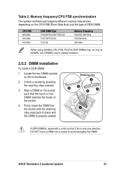
... that it fits in place and the DIMM is keyed with a notch so that the notch on the DIMM matches the break on the motherboard. 2. ASUS Terminator 2 barebone system 31 Table 2: Memory frequency/CPU FSB synchronization The system motherboard supports different memory frequencies depending on the CPU FSB (Front Side Bus) and...
... that it fits in place and the DIMM is keyed with a notch so that the notch on the DIMM matches the break on the motherboard. 2. ASUS Terminator 2 barebone system 31 Table 2: Memory frequency/CPU FSB synchronization The system motherboard supports different memory frequencies depending on the CPU FSB (Front Side Bus) and...
T2-P User Manual
Page 33
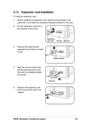
... the card. 2. Before installing the expansion card, read the documentation that you intend to use. Pull the expansion card lock to the chassis. 4 PCI card 5 ASUS Terminator 2 barebone system 33 2.7.2 Expansion card installation To install an expansion card. 1.
... the card. 2. Before installing the expansion card, read the documentation that you intend to use. Pull the expansion card lock to the chassis. 4 PCI card 5 ASUS Terminator 2 barebone system 33 2.7.2 Expansion card installation To install an expansion card. 1.
T2-P User Manual
Page 35
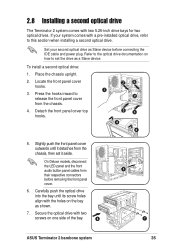
... the chassis. 4. Press the hooks inward to this section when installing a second optical drive. 2.8 Installing a second optical drive The Terminator 2 system comes with the holes on one side of the bay. 6 5 7 ASUS Terminator 2 barebone system 35 Secure the optical drive with a pre-installed optical drive, refer to release the front panel cover from...
... the chassis. 4. Press the hooks inward to this section when installing a second optical drive. 2.8 Installing a second optical drive The Terminator 2 system comes with the holes on one side of the bay. 6 5 7 ASUS Terminator 2 barebone system 35 Secure the optical drive with a pre-installed optical drive, refer to release the front panel cover from...
T2-P User Manual
Page 37
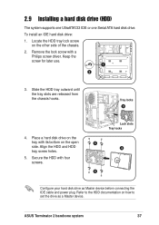
... the tray with its bottom on the other side of the chassis. 2. Keep the screw for later use. 1 2 3. To install an IDE hard disk drive: 1. ASUS Terminator 2 barebone system 37 Refer to the HDD documentation on how to set the drive as Master device before connecting the IDE cable and power plug.
... the tray with its bottom on the other side of the chassis. 2. Keep the screw for later use. 1 2 3. To install an IDE hard disk drive: 1. ASUS Terminator 2 barebone system 37 Refer to the HDD documentation on how to set the drive as Master device before connecting the IDE cable and power plug.
T2-P User Manual
Page 39
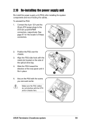
... the PSU side hook with the screw you removed earlier. Make sure the PSU cables do not interfere with the CPU and/or chassis fans. 5 ASUS Terminator 2 barebone system 39 See page 81 for the location of the rear panel until it fits in place. 3 2 4 5.
... the PSU side hook with the screw you removed earlier. Make sure the PSU cables do not interfere with the CPU and/or chassis fans. 5 ASUS Terminator 2 barebone system 39 See page 81 for the location of the rear panel until it fits in place. 3 2 4 5.