T2-AH1 English user manual E2065
Page 4
... Tester 3-14 3.4.5 Cool 'n' Quiet!™ Technology 3-15 3.4.6 ASUS PC Probe II 3-17 3.4.7 AC`97 audio feature 3-23 Chapter 4: Motherboard Info 4.1 Introduction 4-2 4.2 Motherboard layout 4-2 4.3 Jumper 4-3 4.4 Connectors 4-4 Chapter 5: BIOS Information 5.1 Managing and updating your BIOS 5-2 5.1.1 Creating a bootable floppy disk 5-2 5.1.2 ASUS EZ Flash utility 5-3 5.1.3 AFUDOS utility 5-4 5.1.4 ASUS CrashFree BIOS 2 utility 5-6 5.1.5 ASUS Update utility 5-8 5.2 BIOS setup program 5-11 5.2.1 BIOS menu...
... Tester 3-14 3.4.5 Cool 'n' Quiet!™ Technology 3-15 3.4.6 ASUS PC Probe II 3-17 3.4.7 AC`97 audio feature 3-23 Chapter 4: Motherboard Info 4.1 Introduction 4-2 4.2 Motherboard layout 4-2 4.3 Jumper 4-3 4.4 Connectors 4-4 Chapter 5: BIOS Information 5.1 Managing and updating your BIOS 5-2 5.1.1 Creating a bootable floppy disk 5-2 5.1.2 ASUS EZ Flash utility 5-3 5.1.3 AFUDOS utility 5-4 5.1.4 ASUS CrashFree BIOS 2 utility 5-6 5.1.5 ASUS Update utility 5-8 5.2 BIOS setup program 5-11 5.2.1 BIOS menu...
T2-AH1 English user manual E2065
Page 8
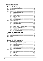
... system settings through the BIOS Setup menus and describes the BIOS parameters. 6. Chapter 4: Motherboard information This chapter gives information about the ASUS T2-AH1 barebone system. Chapter 5: BIOS information This chapter tells how to install components in the ...intended for this guide Audience This guide provides general information and installation instructions about the motherboard that comes with hardware knowledge of the ASUS T2-AH1. This chapter includes the motherboard layout, jumper settings, and connector locations. 5. viii Chapter 1: System introduction This ...
... system settings through the BIOS Setup menus and describes the BIOS parameters. 6. Chapter 4: Motherboard information This chapter gives information about the ASUS T2-AH1 barebone system. Chapter 5: BIOS information This chapter tells how to install components in the ...intended for this guide Audience This guide provides general information and installation instructions about the motherboard that comes with hardware knowledge of the ASUS T2-AH1. This chapter includes the motherboard layout, jumper settings, and connector locations. 5. viii Chapter 1: System introduction This ...
T2-AH1 English user manual E2065
Page 10
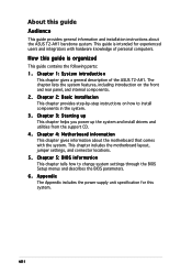
System package contents Check your T2-AH1 system package for the following items. If any of the items is damaged or missing, contact your retailer immediately. User guide 5 . Optional items • Optical drive (CD-ROM/CD-RW/DVD-ROM/DVD-RW) • Floppy disk drive x A H 1 b a r e b o n e s y s t e m with • ASUS motherboard • 250 W PFC power supply unit...
System package contents Check your T2-AH1 system package for the following items. If any of the items is damaged or missing, contact your retailer immediately. User guide 5 . Optional items • Optical drive (CD-ROM/CD-RW/DVD-ROM/DVD-RW) • Floppy disk drive x A H 1 b a r e b o n e s y s t e m with • ASUS motherboard • 250 W PFC power supply unit...
T2-AH1 English user manual E2065
Page 12
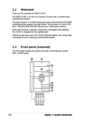
... With these and many more, the T2-AH1 definitely delivers the cutting edge technology for choosing the ASUS T2-AH1! With audio functions, extensive connectivity, and Gigabit LAN capability, the T2-AH1 is an all-in a stylish mini-tower casing, and powered by the ASUS motherboard that supports the AMD Athlon™ ...64 processor for the sophisticated. The system comes in -one barebone system with 1 GHz/800 MHz/400 MHz FSB and up to 2 GB system memory. The ASUS T2-AH1 is designed for Socket 939 with...
... With these and many more, the T2-AH1 definitely delivers the cutting edge technology for choosing the ASUS T2-AH1! With audio functions, extensive connectivity, and Gigabit LAN capability, the T2-AH1 is an all-in a stylish mini-tower casing, and powered by the ASUS motherboard that supports the AMD Athlon™ ...64 processor for the sophisticated. The system comes in -one barebone system with 1 GHz/800 MHz/400 MHz FSB and up to 2 GB system memory. The ASUS T2-AH1 is designed for Socket 939 with...
T2-AH1 English user manual E2065
Page 19
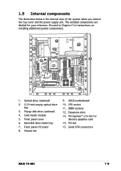
... card 14. Chassis fan 9. The installed components are labeled for your reference. Expansion slots 13. Front panel cover 6. Serial ATA connectors ASUS T2-AH1 1-9 Optical drive (optional) 2. 5.25-inch empty optical drive bay 3. ASUS motherboard 10. PCI slot 15. Front panel I/O board 8. 1.5 Internal components The illustration below is the internal view of the system when...
... card 14. Chassis fan 9. The installed components are labeled for your reference. Expansion slots 13. Front panel cover 6. Serial ATA connectors ASUS T2-AH1 1-9 Optical drive (optional) 2. 5.25-inch empty optical drive bay 3. ASUS motherboard 10. PCI slot 15. Front panel I/O board 8. 1.5 Internal components The illustration below is the internal view of the system when...
T2-AH1 English user manual E2065
Page 22
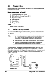
... power supply case, before installing any component, place it on them. • Whenever you plan to install in the system. Central processing unit (CPU) 2. The motherboard comes with the component. 2.1 Preparation Before you proceed, make sure that the standby power LED is ON, in sleep mode or in soft-off mode...
... power supply case, before installing any component, place it on them. • Whenever you plan to install in the system. Central processing unit (CPU) 2. The motherboard comes with the component. 2.1 Preparation Before you proceed, make sure that the standby power LED is ON, in sleep mode or in soft-off mode...
T2-AH1 English user manual E2065
Page 24
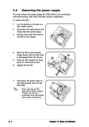
.... 6 4 5 7 7 2-4 Chapter 2: Basic installation The unit may accidentally drop and damage other system components. Slightly lift the PSU. 7. Lay the system on its side on the motherboard, then set the PSU aside. To remove the PSU: 1. Slide the PSU as the zoomed image shows, until the side hook is disengaged from the...
.... 6 4 5 7 7 2-4 Chapter 2: Basic installation The unit may accidentally drop and damage other system components. Slightly lift the PSU. 7. Lay the system on its side on the motherboard, then set the PSU aside. To remove the PSU: 1. Slide the PSU as the zoomed image shows, until the side hook is disengaged from the...
T2-AH1 English user manual E2065
Page 25
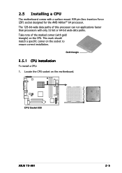
The 128-bit-wide data paths of the marked corner (with only 32-bit or 64-bit wide data paths. Gold triangle 2.5.1 CPU installation To install a CPU: 1. This mark should match a specific corner on the motherboard. CPU Socket 939 ® ASUS T2-AH1 2-5 Take note of this processor can run applications faster than processors with gold triangle) on the CPU. Locate the CPU socket on the socket to ensure correct installation. 2.5 Installing a CPU The motherboard comes with a surface mount 939-pin Zero Insertion Force (ZIF) socket designed for the AMD Athlon™ 64 processor.
The 128-bit-wide data paths of the marked corner (with only 32-bit or 64-bit wide data paths. Gold triangle 2.5.1 CPU installation To install a CPU: 1. This mark should match a specific corner on the motherboard. CPU Socket 939 ® ASUS T2-AH1 2-5 Take note of this processor can run applications faster than processors with gold triangle) on the CPU. Locate the CPU socket on the socket to ensure correct installation. 2.5 Installing a CPU The motherboard comes with a surface mount 939-pin Zero Insertion Force (ZIF) socket designed for the AMD Athlon™ 64 processor.
T2-AH1 English user manual E2065
Page 27
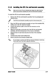
... heatsink assembly on the motherboard. 4. Snap the hook of each locking lever. 7. Hardware monitoring errors may be in the reverse orientation. 5. Connect the CPU fan cable to connect the CPU fan connector! The CPU fan and heatsink assembly may occur if you fail to plug this connector. 6 4 2 5 6 7 7 5 4 3 ASUS T2-AH1 2-7 Remove the CPU fan...
... heatsink assembly on the motherboard. 4. Snap the hook of each locking lever. 7. Hardware monitoring errors may be in the reverse orientation. 5. Connect the CPU fan cable to connect the CPU fan connector! The CPU fan and heatsink assembly may occur if you fail to plug this connector. 6 4 2 5 6 7 7 5 4 3 ASUS T2-AH1 2-7 Remove the CPU fan...
T2-AH1 English user manual E2065
Page 28
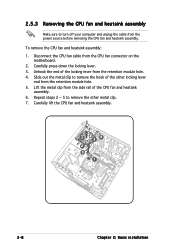
... rail of the CPU fan and heatsink assembly. 6. Carefully press down the locking lever. 3. Lift the metal clip from the CPU fan connector on the motherboard. 2. Slide out the metal clip to remove the hook of the locking lever from the retention module hole. 5. Repeat steps 2 ~ 5 to turn off your computer...
... rail of the CPU fan and heatsink assembly. 6. Carefully press down the locking lever. 3. Lift the metal clip from the CPU fan connector on the motherboard. 2. Slide out the metal clip to remove the hook of the locking lever from the retention module hole. 5. Repeat steps 2 ~ 5 to turn off your computer...
T2-AH1 English user manual E2065
Page 29
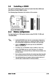
ASUS T2-AH1 2-9 Use any of 128 Mb chips or double-sided x16 memory modules. For optimum compatibility, we recommend that you enable the onboard VGA. • This motherboard does not support memory modules made up of the recommended configurations in the table on the next page. • Install only i d e ... Always install DIMMs with two Double Data Rate (DDR) Dual Inline Memory Module (DIMM) sockets. 2.6 Installing a DIMM The system motherboard comes with the same CAS latency. The following figure illustrates the location of the sockets: DIMM_B1 DIMM_A1 ® 104 Pins 80 Pins...
ASUS T2-AH1 2-9 Use any of 128 Mb chips or double-sided x16 memory modules. For optimum compatibility, we recommend that you enable the onboard VGA. • This motherboard does not support memory modules made up of the recommended configurations in the table on the next page. • Install only i d e ... Always install DIMMs with two Double Data Rate (DDR) Dual Inline Memory Module (DIMM) sockets. 2.6 Installing a DIMM The system motherboard comes with the same CAS latency. The following figure illustrates the location of the sockets: DIMM_B1 DIMM_A1 ® 104 Pins 80 Pins...
T2-AH1 English user manual E2065
Page 33
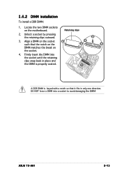
ASUS T2-AH1 2-13 Retaining clips 2. Unlock a socket by pressing the retaining clips outward. 3. Locate the two DIMM sockets on the socket. 3 4 2 4 4. Align a DIMM on the socket 2 such that it fits in only one direction. Firmly insert the DIMM into a socket to avoid damaging the DIMM! 2.6.2 DIMM installation To install a DDR DIMM: 1. DO NOT force a DIMM into the socket until the retaining clips snap back in place and the DIMM is properly seated. 1 A DDR DIMM is keyed with a notch so that the notch on the DIMM matches the break on the motherboard.
ASUS T2-AH1 2-13 Retaining clips 2. Unlock a socket by pressing the retaining clips outward. 3. Locate the two DIMM sockets on the socket. 3 4 2 4 4. Align a DIMM on the socket 2 such that it fits in only one direction. Firmly insert the DIMM into a socket to avoid damaging the DIMM! 2.6.2 DIMM installation To install a DDR DIMM: 1. DO NOT force a DIMM into the socket until the retaining clips snap back in place and the DIMM is properly seated. 1 A DDR DIMM is keyed with a notch so that the notch on the DIMM matches the break on the motherboard.
T2-AH1 English user manual E2065
Page 34
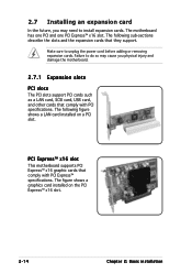
... one PCI and one PCI Express™ x16 slot. 2.7 Installing an expansion card In the future, you may cause you physical injury and damage the motherboard. 2.7.1 Expansion slots PCI slots The PCI slots support PCI cards such as a LAN card, SCSI card, USB card, and other cards that they support. The... unplug the power cord before adding or removing expansion cards. The figure shows a graphics card installed on a PCI slot. PCI Express™ x16 slot This motherboard supports PCI Express™ x16 graphic cards that comply with PCI specifications.
... one PCI and one PCI Express™ x16 slot. 2.7 Installing an expansion card In the future, you may cause you physical injury and damage the motherboard. 2.7.1 Expansion slots PCI slots The PCI slots support PCI cards such as a LAN card, SCSI card, USB card, and other cards that they support. The... unplug the power cord before adding or removing expansion cards. The figure shows a graphics card installed on a PCI slot. PCI Express™ x16 slot This motherboard supports PCI Express™ x16 graphic cards that comply with PCI specifications.
T2-AH1 English user manual E2065
Page 36
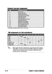
...* IRQ Holder for PCI Steering 12* PS/2 Compatible Mouse Port 13 Numeric Data Processor 15* Secondary IDE Channel * These IRQs are usually available for this motherboard USB0 USB1 USB2 USB3 AC '97 Onboard 1394 Onboard LAN Onboard PCIE A B C DE F -- used -- -- -- -- -- -- -- -- -- -- -- -- -- -- -- -- -- -- shared...
...* IRQ Holder for PCI Steering 12* PS/2 Compatible Mouse Port 13 Numeric Data Processor 15* Secondary IDE Channel * These IRQs are usually available for this motherboard USB0 USB1 USB2 USB3 AC '97 Onboard 1394 Onboard LAN Onboard PCIE A B C DE F -- used -- -- -- -- -- -- -- -- -- -- -- -- -- -- -- -- -- -- shared...
T2-AH1 English user manual E2065
Page 38
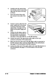
... the IDE connector. 12. Carefully push the optical drive into the bay until its screw holes align with Pin 1 on the motherboard. See page 2-25 for details on the motherboard. Make sure that the other end of the optical drive, matching the red stripe on the cable with the holes on one...
... the IDE connector. 12. Carefully push the optical drive into the bay until its screw holes align with Pin 1 on the motherboard. See page 2-25 for details on the motherboard. Make sure that the other end of the optical drive, matching the red stripe on the cable with the holes on one...
T2-AH1 English user manual E2065
Page 40
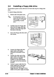
... floppy disk drive. Connect a power cable from the power supply unit to the signal connector at the back of the drive. 5. For instructions on the motherboard. See page 4-6 for details on the power supply unit plugs. 6 4 2-20 Chapter 2: Basic installation 2.9 Installing a floppy disk drive The barebone system comes with the holes...
... floppy disk drive. Connect a power cable from the power supply unit to the signal connector at the back of the drive. 5. For instructions on the motherboard. See page 4-6 for details on the power supply unit plugs. 6 4 2-20 Chapter 2: Basic installation 2.9 Installing a floppy disk drive The barebone system comes with the holes...
T2-AH1 English user manual E2065
Page 42
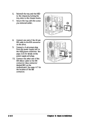
... 40-pin IDE cable to the IDE connector (blue connector labeled IDE) on the power supply unit plugs. 9 10. See page 4-7 for details on the motherboard. Reinstall the tray and the HDD to the chassis by locking the tray slots to the HDD power connector. Secure the tray with the screw...
... 40-pin IDE cable to the IDE connector (blue connector labeled IDE) on the power supply unit plugs. 9 10. See page 4-7 for details on the motherboard. Reinstall the tray and the HDD to the chassis by locking the tray slots to the HDD power connector. Secure the tray with the screw...
T2-AH1 English user manual E2065
Page 43
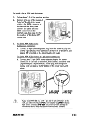
... 15-pin SATA power adapter plug to a 4-pin (female) power plug from becoming unstable. For Serial ATA HDDs without a 4-pin power connector: b. ASUS T2-AH1 2-23 Connect a 4-pin (female) power plug from the power supply unit to the 4-pin (male) power connector at the back of the drive, then... the back, use both to prevent damage to components and to a SATA connector on the power supply unit plugs. See page 4-8 for details on the motherboard. D O N O T use either the 15-pin SATA power adapter plug O R the legacy 4-pin power connector. See page 2-25 for 2 the location of...
... 15-pin SATA power adapter plug to a 4-pin (female) power plug from becoming unstable. For Serial ATA HDDs without a 4-pin power connector: b. ASUS T2-AH1 2-23 Connect a 4-pin (female) power plug from the power supply unit to the 4-pin (male) power connector at the back of the drive, then... the back, use both to prevent damage to components and to a SATA connector on the power supply unit plugs. See page 4-8 for details on the motherboard. D O N O T use either the 15-pin SATA power adapter plug O R the legacy 4-pin power connector. See page 2-25 for 2 the location of...

T2-AH1 English user manual E2065
Page 44
...(PSU) after installing the system components and reconnecting the cables, . Connect the 4-pin 12 V power plug to the ATXPWR connector on the motherboard. Slide the PSU toward the direction of the optical drive bay. 5. Connect the 24-pin ATX power plug to the ATX12V connector on the...rear panel until it fits in place. 5 6. To reinstall the PSU: 1. Align the PSU side hook with the 4 3 metal slot located on the motherboard. 2. Make sure the PSU cables do not interfere with the screw you removed earlier. See page 4-6 for the location of power connectors. 2 1 3. Secure...
...(PSU) after installing the system components and reconnecting the cables, . Connect the 4-pin 12 V power plug to the ATXPWR connector on the motherboard. Slide the PSU toward the direction of the optical drive bay. 5. Connect the 24-pin ATX power plug to the ATX12V connector on the...rear panel until it fits in place. 5 6. To reinstall the PSU: 1. Align the PSU side hook with the 4 3 metal slot located on the motherboard. 2. Make sure the PSU cables do not interfere with the screw you removed earlier. See page 4-6 for the location of power connectors. 2 1 3. Secure...
T2-AH1 English user manual E2065
Page 48
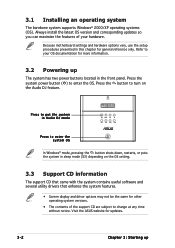
...updates. 3-2 Chapter 3: Starting up The system has two power buttons located in the front panel. Press the button to your hardware. Visit the ASUS website for more information. 3.2 Powering up Press the system power button ( ) to change at any time without notice. Refer to turn on the...the latest OS version and corresponding updates so you can maximize the features of the support CD are subject to enter the OS. Because motherboard settings and hardware options vary, use the setup procedures presented in sleep mode (S3) depending on the Audio DJ feature. 3.1 Installing an...
...updates. 3-2 Chapter 3: Starting up The system has two power buttons located in the front panel. Press the button to your hardware. Visit the ASUS website for more information. 3.2 Powering up Press the system power button ( ) to change at any time without notice. Refer to turn on the...the latest OS version and corresponding updates so you can maximize the features of the support CD are subject to enter the OS. Because motherboard settings and hardware options vary, use the setup procedures presented in sleep mode (S3) depending on the Audio DJ feature. 3.1 Installing an...