
User Guide
Page 1
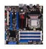
Motherboard Rampage II GENE
Motherboard Rampage II GENE
User Guide
Page 3
...Contents...iii Notices...viii Safety information ix About this guide x Rampage II GENE specifications summary xii Chapter 1: Product introduction 1.1 Welcome 1-1 1.2 Package contents 1-1 1.3 Special features 1-2 1.3.1 Product highlights 1-2 1.3.2 ROG Intelligent Performance & Overclocking features... 1-3 1.3.3 ROG unique features 1-4 1.3.4 ASUS special features 1-5 Chapter 2: Hardware information 2.1 Before you proceed 2-1 2.2 Motherboard overview 2-6 2.2.1 Motherboard layout 2-6 2.2.2 Layout contents 2-7 2.2.3 Placement direction 2-8 2.2.4 Screw holes 2-8 2.3 Central Processing...
...Contents...iii Notices...viii Safety information ix About this guide x Rampage II GENE specifications summary xii Chapter 1: Product introduction 1.1 Welcome 1-1 1.2 Package contents 1-1 1.3 Special features 1-2 1.3.1 Product highlights 1-2 1.3.2 ROG Intelligent Performance & Overclocking features... 1-3 1.3.3 ROG unique features 1-4 1.3.4 ASUS special features 1-5 Chapter 2: Hardware information 2.1 Before you proceed 2-1 2.2 Motherboard overview 2-6 2.2.1 Motherboard layout 2-6 2.2.2 Layout contents 2-7 2.2.3 Placement direction 2-8 2.2.4 Screw holes 2-8 2.3 Central Processing...

User Guide
Page 9
...equipment) should not be placed in your area. If you add a device. • Before connecting or removing signal cables from the motherboard, ensure that the power cables for disposal of parts and recycling. This symbol of the crossed out wheeled bin indicates that your power ...supply is broken, do not try to enable proper reuse of electronic products. DO NOT throw the motherboard in municipal waste. Operation safety • Before installing the motherboard and adding devices on a stable surface. • If you encounter technical problems with the package. •...
...equipment) should not be placed in your area. If you add a device. • Before connecting or removing signal cables from the motherboard, ensure that the power cables for disposal of parts and recycling. This symbol of the crossed out wheeled bin indicates that your power ...supply is broken, do not try to enable proper reuse of electronic products. DO NOT throw the motherboard in municipal waste. Operation safety • Before installing the motherboard and adding devices on a stable surface. • If you encounter technical problems with the package. •...

User Guide
Page 10
...8226; Appendix: Debug code table The Appendix lists the debug code table for product and software updates. 1. ASUS websites The ASUS website provides updated information on the motherboard. • Chapter 3: BIOS setup This chapter tells how to the following parts: • Chapter 1: ...Product introduction This chapter describes the features of the switches, jumpers, and connectors on ASUS hardware and software products. These documents ...
...8226; Appendix: Debug code table The Appendix lists the debug code table for product and software updates. 1. ASUS websites The ASUS website provides updated information on the motherboard. • Chapter 3: BIOS setup This chapter tells how to the following parts: • Chapter 1: ...Product introduction This chapter describes the features of the switches, jumpers, and connectors on ASUS hardware and software products. These documents ...

User Guide
Page 15
This chapter describes the motherboard features and the new technologies it supports. Chapter 1: 1Product introduction
This chapter describes the motherboard features and the new technologies it supports. Chapter 1: 1Product introduction
User Guide
Page 17
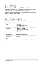
.... Thank you start installing the motherboard, and hardware devices on it another standout in -1 ASUS Q-Connector Kit 1 x I/O Shield 1 x Cable ties 1 x ROG theme label Application DVD ROG motherboard support DVD Documentation User guide If any of ASUS quality motherboards! Before you for the following items. Motherboard ROG Rampage II GENE Cables 1 x SLI cable 1...65533;s�te�r 1 x 2-in the long line of the above items is damaged or missing, contact your motherboard package for buying an ROG Rampage II GENE motherboard! 1.1 Welcome! ROG Rampage II GENE 1-1
.... Thank you start installing the motherboard, and hardware devices on it another standout in -1 ASUS Q-Connector Kit 1 x I/O Shield 1 x Cable ties 1 x ROG theme label Application DVD ROG motherboard support DVD Documentation User guide If any of ASUS quality motherboards! Before you for the following items. Motherboard ROG Rampage II GENE Cables 1 x SLI cable 1...65533;s�te�r 1 x 2-in the long line of the above items is damaged or missing, contact your motherboard package for buying an ROG Rampage II GENE motherboard! 1.1 Welcome! ROG Rampage II GENE 1-1

User Guide
Page 18
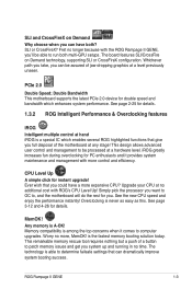
... up to join in the Republic of Gamers. Green ASUS This motherboard and its packaging comply with the European Union's Restriction on the environment. Intel® Core™ i7 Processor Extreme Edition / Core™ i7 Processor support This motherboard supports the latest Intel® Core™ i7 processors in the world. Intel® Core™...
... up to join in the Republic of Gamers. Green ASUS This motherboard and its packaging comply with the European Union's Restriction on the environment. Intel® Core™ i7 Processor Extreme Edition / Core™ i7 Processor support This motherboard supports the latest Intel® Core™ i7 processors in the world. Intel® Core™...
User Guide
Page 19
... disposal of the motherboard at any stage! Upgrade your CPU at a level previously unseen. Overclocking is A-OK! Any memory is never as easy as this. This remarkable memory rescue tool requires nothing but a push of jaw-dropping graphics at no time. ROG Rampage II GENE 1-3 The board ... for details. SLI or CrossFireX? See page 2-25 for you could have both multi-GPU setups. Worry no longer because with the ROG Rampage II GENE, you can have a more , MemOK! Memory compatibility is able to computer upgrades. See the new CPU speed and enjoy the performance instantly...
... disposal of the motherboard at any stage! Upgrade your CPU at a level previously unseen. Overclocking is A-OK! Any memory is never as easy as this. This remarkable memory rescue tool requires nothing but a push of jaw-dropping graphics at no time. ROG Rampage II GENE 1-3 The board ... for details. SLI or CrossFireX? See page 2-25 for you could have both multi-GPU setups. Worry no longer because with the ROG Rampage II GENE, you can have a more , MemOK! Memory compatibility is able to computer upgrades. See the new CPU speed and enjoy the performance instantly...

User Guide
Page 20
...details. The Loadline calibration ensures stable and optimal CPU voltage under heavy loading. The COP EX allows overclockers to the gamers of overheating. It can also be used to offer games exceptional game sound with absolute quality. �S�e�e�... HD Play in extreme fidelity! Maintaining ample voltage support for details. 1-4 Chapter 1: Product Introduction It helps overclockers enjoy the motherboard's ultimate OC capabilities and benchmark scores. 1.3.3 ROG unique features SupremeFX X-Fi features Listen with burn proof protection to optimal performance...
...details. The Loadline calibration ensures stable and optimal CPU voltage under heavy loading. The COP EX allows overclockers to the gamers of overheating. It can also be used to offer games exceptional game sound with absolute quality. �S�e�e�... HD Play in extreme fidelity! Maintaining ample voltage support for details. 1-4 Chapter 1: Product Introduction It helps overclockers enjoy the motherboard's ultimate OC capabilities and benchmark scores. 1.3.3 ROG unique features SupremeFX X-Fi features Listen with burn proof protection to optimal performance...

User Guide
Page 22
...clear CMOS data. See page 3-6 for details. function. 1-6 Chapter 1: Product Introduction See page 2-39 for details. Profile The motherboard features the ASUS O.C. Simply launch this tool and update BIOS using a USB flash disk without preparing an additional floppy diskette or using C.P.R. The product... incorporates the Kaspersky® Anti-Virus engine, which is renowned for individual users and home offices. ASUS O.C. ASUS EZ Flash 2 EZ Flash 2 is no need to open the system chassis to overclocking failure, there is a user-friendly BIOS...
...clear CMOS data. See page 3-6 for details. function. 1-6 Chapter 1: Product Introduction See page 2-39 for details. Profile The motherboard features the ASUS O.C. Simply launch this tool and update BIOS using a USB flash disk without preparing an additional floppy diskette or using C.P.R. The product... incorporates the Kaspersky® Anti-Virus engine, which is renowned for individual users and home offices. ASUS O.C. ASUS EZ Flash 2 EZ Flash 2 is no need to open the system chassis to overclocking failure, there is a user-friendly BIOS...

User Guide
Page 23
It Chapter 2: includes description of the jumpers and connectors on the motherboard. 2 Hardware information This chapter lists the hardware setup procedures that you have to perform when installing system components.
It Chapter 2: includes description of the jumpers and connectors on the motherboard. 2 Hardware information This chapter lists the hardware setup procedures that you have to perform when installing system components.
User Guide
Page 24
Chapter summary 2 2.1 Before you proceed 2-1 2.2 Motherboard overview 2-6 2.3 Central Processing Unit (CPU 2-9 2.4 System memory 2-15 2.5 Expansion slots 2-23 2.6 Jumper 2-27 2.7 Connectors 2-28 2.8 Starting up for the first time 2-43 2.9 Turning off the computer 2-44 ROG Rampage II GENE
Chapter summary 2 2.1 Before you proceed 2-1 2.2 Motherboard overview 2-6 2.3 Central Processing Unit (CPU 2-9 2.4 System memory 2-15 2.5 Expansion slots 2-23 2.6 Jumper 2-27 2.7 Connectors 2-28 2.8 Starting up for the first time 2-43 2.9 Turning off the computer 2-44 ROG Rampage II GENE
User Guide
Page 25
2.1 Before you proceed Take note of the following precautions before you install motherboard components or change any motherboard settings. • Unplug the power cord from the wall socket before touching any component. • Use a grounded wrist strap or touch a safely...supply case, before handling components to avoid damaging them due to static electricity. • Hold components by the edges to the motherboard, peripherals, and/or components. ROG Rampage II GENE 2-1 Failure to do so may cause severe damage to avoid touching the ICs on them. • Whenever you uninstall any ...
2.1 Before you proceed Take note of the following precautions before you install motherboard components or change any motherboard settings. • Unplug the power cord from the wall socket before touching any component. • Use a grounded wrist strap or touch a safely...supply case, before handling components to avoid damaging them due to static electricity. • Hold components by the edges to the motherboard, peripherals, and/or components. ROG Rampage II GENE 2-1 Failure to do so may cause severe damage to avoid touching the ICs on them. • Whenever you uninstall any ...

User Guide
Page 26
... illustration below for LED definition. There are also an LED for hard disk drive activity and an onboard switch for power status. Onboard LEDs The motherboard comes with LEDs that indicate the voltage conditions of the CPU LED and the table below for the location of CPU, memory, northbridge, and southbridge...
... illustration below for LED definition. There are also an LED for hard disk drive activity and an onboard switch for power status. Onboard LEDs The motherboard comes with LEDs that indicate the voltage conditions of the CPU LED and the table below for the location of CPU, memory, northbridge, and southbridge...

User Guide
Page 28
Memory LED Refer to indicate the hard disk activity. 3. Normal (green) DRAM Bus Voltage 1.51106-1.72306 High (yellow) 1.73631-2.31931 Crazy (red) 2.33256- 4. It blinks when data is no hard disk drive connected to the motherboard or when the hard disk drive does not function. 2-4 Chapter 2: Hardware information Hard Disk LED The hard disk LED is designed to the illustration below for the location of the memory LED and the table below for LED definition. The LED does not light up when there is being written into or read from the hard disk drive.
Memory LED Refer to indicate the hard disk activity. 3. Normal (green) DRAM Bus Voltage 1.51106-1.72306 High (yellow) 1.73631-2.31931 Crazy (red) 2.33256- 4. It blinks when data is no hard disk drive connected to the motherboard or when the hard disk drive does not function. 2-4 Chapter 2: Hardware information Hard Disk LED The hard disk LED is designed to the illustration below for the location of the memory LED and the table below for LED definition. The LED does not light up when there is being written into or read from the hard disk drive.

User Guide
Page 29
... the system is ready to indicate that lights up to boot. MemOK! LED blinks while the system is ON, in sleep mode, or in any motherboard component. The illustration below shows the location of the onboard power-on switch. 6. LED The MemOK! switch. This is a reminder that you should... the power cable before you turn on switch that the system is loading failsafe settings for memory compatibility after pressing the MemOK! ROG Rampage II GENE 2-5 Wait till the flash stops before removing or plugging in soft‑off mode. 5. When you press the power-on switch.
... the system is ready to indicate that lights up to boot. MemOK! LED blinks while the system is ON, in sleep mode, or in any motherboard component. The illustration below shows the location of the onboard power-on switch. 6. LED The MemOK! switch. This is a reminder that you should... the power cable before you turn on switch that the system is loading failsafe settings for memory compatibility after pressing the MemOK! ROG Rampage II GENE 2-5 Wait till the flash stops before removing or plugging in soft‑off mode. 5. When you press the power-on switch.

User Guide
Page 30
2.2 Motherboard overview 2.2.1 Motherboard layout 2-6 Chapter 2: Hardware information
2.2 Motherboard overview 2.2.1 Motherboard layout 2-6 Chapter 2: Hardware information

User Guide
Page 32
The edge with external ports goes to the chassis. Doing so can damage the motherboard. Place this side towards the rear of the chassis as indicated in the image below. 2.2.4 Screw holes Place eight (8) screws into the chassis in the correct orientation. DO NOT overtighten the screws! 2.2.3 Placement direction When installing the motherboard, ensure that you place it into the holes indicated by circles to secure the motherboard to the rear part of the chassis 2-8 Chapter 2: Hardware information
The edge with external ports goes to the chassis. Doing so can damage the motherboard. Place this side towards the rear of the chassis as indicated in the image below. 2.2.4 Screw holes Place eight (8) screws into the chassis in the correct orientation. DO NOT overtighten the screws! 2.2.3 Placement direction When installing the motherboard, ensure that you place it into the holes indicated by circles to secure the motherboard to the rear part of the chassis 2-8 Chapter 2: Hardware information
User Guide
Page 33
... system stability. • Upon purchase of repair only if the damage is shipment/transit-related. • Keep the cap after installing the motherboard. ASUS will shoulder the cost of the motherboard, ensure that all power cables are not bent. Contact your retailer immediately if the PnP cap is on the LGA1366 socket. •... if you see any damage to the socket contacts resulting from incorrect CPU installation/removal, or misplacement/loss/ incorrect removal of the PnP cap. ROG Rampage II GENE 2-9
... system stability. • Upon purchase of repair only if the damage is shipment/transit-related. • Keep the cap after installing the motherboard. ASUS will shoulder the cost of the motherboard, ensure that all power cables are not bent. Contact your retailer immediately if the PnP cap is on the LGA1366 socket. •... if you see any damage to the socket contacts resulting from incorrect CPU installation/removal, or misplacement/loss/ incorrect removal of the PnP cap. ROG Rampage II GENE 2-9

User Guide
Page 34
Locate the CPU socket on your thumb (A), then move it is on the motherboard. Press the load lever with your left (B) until it to the socket pins, do not remove the PnP cap unless you and the load lever is released from the retention tab. To prevent damage to the left . 2. 2.3.1 Installing the CPU To install a CPU: 1. Retention tab A B Load lever 2-10 Chapter 2: Hardware information Before installing the CPU, ensure that the cam box is facing towards you are installing a CPU.
Locate the CPU socket on your thumb (A), then move it is on the motherboard. Press the load lever with your left (B) until it to the socket pins, do not remove the PnP cap unless you and the load lever is released from the retention tab. To prevent damage to the left . 2. 2.3.1 Installing the CPU To install a CPU: 1. Retention tab A B Load lever 2-10 Chapter 2: Hardware information Before installing the CPU, ensure that the cam box is facing towards you are installing a CPU.


