
User Guide
Page 4
... the computer 2-44 2.9.1 Using the OS shut down function 2-44 2.9.2 Using the dual function power switch 2-44 Chapter 3: BIOS setup 3.1 Managing and updating your BIOS 3-1 3.1.1 ASUS Update utility 3-1 3.1.2 ASUS EZ Flash 2 utility 3-4 3.1.3 ASUS CrashFree BIOS 3 utility 3-5 3.2 BIOS setup program 3-6 3.2.1 BIOS menu screen 3-7 3.2.2 Menu bar 3-7 3.2.3 Navigation keys 3-7 3.2.4 Menu items 3-8 3.2.5 Submenu items 3-8 3.2.6 Configuration fields 3-8 3.2.7 Pop-up window 3-8 3.2.8 Scroll bar 3-8 3.2.9 General...
... the computer 2-44 2.9.1 Using the OS shut down function 2-44 2.9.2 Using the dual function power switch 2-44 Chapter 3: BIOS setup 3.1 Managing and updating your BIOS 3-1 3.1.1 ASUS Update utility 3-1 3.1.2 ASUS EZ Flash 2 utility 3-4 3.1.3 ASUS CrashFree BIOS 3 utility 3-5 3.2 BIOS setup program 3-6 3.2.1 BIOS menu screen 3-7 3.2.2 Menu bar 3-7 3.2.3 Navigation keys 3-7 3.2.4 Menu items 3-8 3.2.5 Submenu items 3-8 3.2.6 Configuration fields 3-8 3.2.7 Pop-up window 3-8 3.2.8 Scroll bar 3-8 3.2.9 General...
User Guide
Page 7
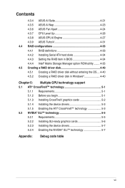
Contents 4.3.4 ASUS AI Suite 4-21 4.3.5 ASUS AI Nap 4-23 4.3.6 ASUS Fan Xpert 4-24 4.3.7 CPU Level Up 4-26 4.3.8 ASUS EPU-6 Engine 4-27 4.3.9 ASUS TurboV 4-31 4.4 RAID configurations 4-33 4.4.1 RAID definitions 4-33 4.4.2 Installing Serial ATA hard disks 4-34 4.4.3 Setting the RAID item in BIOS 4-34 4.4.4 Intel® Matrix Storage Manager option ROM utility......... 4-35 4.5 Creating a RAID driver disk 4-40...
Contents 4.3.4 ASUS AI Suite 4-21 4.3.5 ASUS AI Nap 4-23 4.3.6 ASUS Fan Xpert 4-24 4.3.7 CPU Level Up 4-26 4.3.8 ASUS EPU-6 Engine 4-27 4.3.9 ASUS TurboV 4-31 4.4 RAID configurations 4-33 4.4.1 RAID definitions 4-33 4.4.2 Installing Serial ATA hard disks 4-34 4.4.3 Setting the RAID item in BIOS 4-34 4.4.4 Intel® Matrix Storage Manager option ROM utility......... 4-35 4.5 Creating a RAID driver disk 4-40...

User Guide
Page 10
... supports. • Chapter 2: Hardware information This chapter lists the hardware setup procedures that you need when installing and configuring the motherboard. ASUS websites The ASUS website provides updated information on the motherboard. • Chapter 3: BIOS setup This chapter tells how to install and configure multiple ATI® CrossFireX™ and NVIDIA® SLI™ graphics...
... supports. • Chapter 2: Hardware information This chapter lists the hardware setup procedures that you need when installing and configuring the motherboard. ASUS websites The ASUS website provides updated information on the motherboard. • Chapter 3: BIOS setup This chapter tells how to install and configure multiple ATI® CrossFireX™ and NVIDIA® SLI™ graphics...
User Guide
Page 13
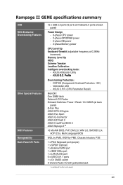
...at 0.2MHz increment) Memory Level Up iROG Extreme Tweaker Loadline Calibration Intelligent overclocking tools: - Rampage II GENE specifications summary USB ROG Exclusive Overclocking Features Other Special Features BIOS Features Manageability Back Panel I/O Ports 12 x USB 2.0 ports (6 ports at midboard; 6...Tweakit (adjustable frequency at back panel) Q-Fan Plus ASUS EPU-6 Engine ASUS Fan Xpert ASUS Q-Connector ASUS EZ Flash 2 ASUS CrashFree BIOS 3 ASUS MyLogo 3™ 16 Mb AMI BIOS, PnP, DMI 2.0, WfM 2.0, SM BIOS 2.4, ACPI 2.0a, Multi-Language BIOS WOL by PME, WOR by PME, Chassis Intrusion,...
...at 0.2MHz increment) Memory Level Up iROG Extreme Tweaker Loadline Calibration Intelligent overclocking tools: - Rampage II GENE specifications summary USB ROG Exclusive Overclocking Features Other Special Features BIOS Features Manageability Back Panel I/O Ports 12 x USB 2.0 ports (6 ports at midboard; 6...Tweakit (adjustable frequency at back panel) Q-Fan Plus ASUS EPU-6 Engine ASUS Fan Xpert ASUS Q-Connector ASUS EZ Flash 2 ASUS CrashFree BIOS 3 ASUS MyLogo 3™ 16 Mb AMI BIOS, PnP, DMI 2.0, WfM 2.0, SM BIOS 2.4, ACPI 2.0a, Multi-Language BIOS WOL by PME, WOR by PME, Chassis Intrusion,...
User Guide
Page 21
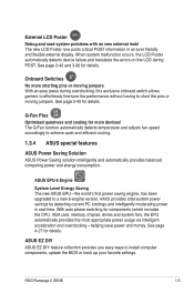
... device failure and translates the errors on the LCD during overclocking, this exclusive onboard switch allows gamers to effortlessly fine-tune the performance without having to a new 6-engine version, which includes the...BIOS or back up your favorite settings. ASUS EZ DIY ASUS EZ DIY feature collection provides you easy ways to achieve quiet and efficient cooling. 1.3.4 ASUS special features ASUS Power Saving Solution ASUS Power Saving solution intelligently and automatically provides balanced computing power and energy consumption. See page 2-42 and 3-30 for details. ROG Rampage II GENE...
... device failure and translates the errors on the LCD during overclocking, this exclusive onboard switch allows gamers to effortlessly fine-tune the performance without having to a new 6-engine version, which includes the...BIOS or back up your favorite settings. ASUS EZ DIY ASUS EZ DIY feature collection provides you easy ways to achieve quiet and efficient cooling. 1.3.4 ASUS special features ASUS Power Saving Solution ASUS Power Saving solution intelligently and automatically provides balanced computing power and energy consumption. See page 2-42 and 3-30 for details. ROG Rampage II GENE...

User Guide
Page 22
...and accurate. C.P.R. (CPU Parameter Recall) When the system hangs due to overclocking failure, there is a user-friendly BIOS update utility. Profile The motherboard features the ASUS O.C. ASUS EZ Flash 2 EZ Flash 2 is no need to open the system chassis to clear CMOS data. Due to the... a separate file, giving users freedom to share and distribute their favorite settings. ASUS O.C. The BIOS settings can update your BIOS in one complete module. Simply launch this tool and update BIOS using C.P.R. Kaspersky® Anti-Virus The best protection from viruses and spyware Kaspersky...
...and accurate. C.P.R. (CPU Parameter Recall) When the system hangs due to overclocking failure, there is a user-friendly BIOS update utility. Profile The motherboard features the ASUS O.C. ASUS EZ Flash 2 EZ Flash 2 is no need to open the system chassis to clear CMOS data. Due to the... a separate file, giving users freedom to share and distribute their favorite settings. ASUS O.C. The BIOS settings can update your BIOS in one complete module. Simply launch this tool and update BIOS using C.P.R. Kaspersky® Anti-Virus The best protection from viruses and spyware Kaspersky...

User Guide
Page 26
...an LED for hard disk drive activity and an onboard switch for power status. For more information about voltage adjustment, refer to display in BIOS. CPU LED The CPU LED has three voltage displays: CPU Voltage, CPU PLL Voltage and QPI/DRAM Core voltage; CPU Voltage CPU ...illustration below for the location of CPU, memory, northbridge, and southbridge. You may adjust the voltages in BIOS. you can select the voltage to 3.3 Extreme Tweaker menu. 1. Onboard LEDs The motherboard comes with LEDs that indicate the voltage conditions of the CPU LED and the table below for LED definition...
...an LED for hard disk drive activity and an onboard switch for power status. For more information about voltage adjustment, refer to display in BIOS. CPU LED The CPU LED has three voltage displays: CPU Voltage, CPU PLL Voltage and QPI/DRAM Core voltage; CPU Voltage CPU ...illustration below for the location of CPU, memory, northbridge, and southbridge. You may adjust the voltages in BIOS. you can select the voltage to 3.3 Extreme Tweaker menu. 1. Onboard LEDs The motherboard comes with LEDs that indicate the voltage conditions of the CPU LED and the table below for LED definition...

User Guide
Page 27
... ICH PCIE Voltage. Refer to display in BIOS. IOH Voltage IOH PCIE Voltage ICH Voltage ICH PCIE Voltage Normal (green) 1.11341-1.39166 1.51106-1.69656 1.11341-1.59041 1.51106-1.61706 High (yellow) 1.40491-1.64341 1.70981-1.84231 1.60366-1.84216 1.63031-1.80256 Crazy (red) 1.65666- 1.85556- 1.85541- 1.81581- ROG Rampage II GENE 2-3 Northbridge/Southbridge LEDs The northbridge and...
... ICH PCIE Voltage. Refer to display in BIOS. IOH Voltage IOH PCIE Voltage ICH Voltage ICH PCIE Voltage Normal (green) 1.11341-1.39166 1.51106-1.69656 1.11341-1.59041 1.51106-1.61706 High (yellow) 1.40491-1.64341 1.70981-1.84231 1.60366-1.84216 1.63031-1.80256 Crazy (red) 1.65666- 1.85556- 1.85541- 1.81581- ROG Rampage II GENE 2-3 Northbridge/Southbridge LEDs The northbridge and...
User Guide
Page 41
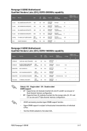
... memory configuration. • ASUS exclusively provides hyper DIMM support function. • Hyper DIMM support is subject to the physical characteristics of 2) SS N/A Heat-Sink Package 8 • • Side(s): SS - ROG Rampage II GENE 2-17 SS N/A SS ...• • 2 • 1.65 • 1.9 • • Rampage II GENE Motherboard Qualified Vendors Lists (QVL) DDR3-1800MHz capability Vendor Part No. DIMM socket Size SS/ DS Chip Brand Chip NO. Timing DIMM (BIOS) Voltage support (Optional) A* B* CORSAIR CM3X1024-1800C7DIN(XMP) 1GB SS N/A Heat-Sink...
... memory configuration. • ASUS exclusively provides hyper DIMM support function. • Hyper DIMM support is subject to the physical characteristics of 2) SS N/A Heat-Sink Package 8 • • Side(s): SS - ROG Rampage II GENE 2-17 SS N/A SS ...• • 2 • 1.65 • 1.9 • • Rampage II GENE Motherboard Qualified Vendors Lists (QVL) DDR3-1800MHz capability Vendor Part No. DIMM socket Size SS/ DS Chip Brand Chip NO. Timing DIMM (BIOS) Voltage support (Optional) A* B* CORSAIR CM3X1024-1800C7DIN(XMP) 1GB SS N/A Heat-Sink...

User Guide
Page 42
Rampage II GENE Motherboard Qualified Vendors Lists (QVL) DDR3-1600MHz capability Vendor Part No. Size SS/ DS Chip Chip NO. A-DATA A-DATA CORSAIR CORSAIR CORSAIR CORSAIR CORSAIR CORSAIR CORSAIR ...-Sink Package Heat-Sink Package Heat-Sink Package Heat-Sink Package Heat-Sink Package Heat-Sink Package Heat-Sink Package Heat-Sink Package Timing Dimm(Bios) 8-8-8-24 (1333-9-9-9-24) 7-7-7-20 (1333-9-9-9-24) 7-7-7-20 (1333-9-9-9-24) 8-8-8-24 (1601-8-8-8-24) 9-9-9-24 (1601-9-9-9-24) Voltage DIMM socket support (Optional) A* B* C* D* 1.651.85 •• •...
Rampage II GENE Motherboard Qualified Vendors Lists (QVL) DDR3-1600MHz capability Vendor Part No. Size SS/ DS Chip Chip NO. A-DATA A-DATA CORSAIR CORSAIR CORSAIR CORSAIR CORSAIR CORSAIR CORSAIR ...-Sink Package Heat-Sink Package Heat-Sink Package Heat-Sink Package Heat-Sink Package Heat-Sink Package Heat-Sink Package Heat-Sink Package Timing Dimm(Bios) 8-8-8-24 (1333-9-9-9-24) 7-7-7-20 (1333-9-9-9-24) 7-7-7-20 (1333-9-9-9-24) 8-8-8-24 (1601-8-8-8-24) 9-9-9-24 (1601-9-9-9-24) Voltage DIMM socket support (Optional) A* B* C* D* 1.651.85 •• •...

User Guide
Page 43
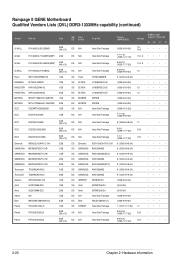
Rampage II GENE Motherboard Qualified Vendors Lists (QVL) DDR3-1600MHz capability (continued) Vendor Part No. Cell Shock CS322271 Elixier M2F2G64CB8HA4N-DG Mushkin 996657 Patriot PVT33G1600ELK... • • • 2.0 • • • • 1.65 • • • • 1.65 • • • • Rampage II GENE Motherboard Qualified Vendors Lists (QVL) DDR3-1333MHz capability Vendor Part No. Timing DIMM (BIOS) Heat-Sink Package J1108BABG-DJ-E J1108BABG-DJ-E(ECC) J1108BABG-DJ-E J1108BABG-DJ-E(ECC) Heat-Sink Package Heat-Sink Package...
Rampage II GENE Motherboard Qualified Vendors Lists (QVL) DDR3-1600MHz capability (continued) Vendor Part No. Cell Shock CS322271 Elixier M2F2G64CB8HA4N-DG Mushkin 996657 Patriot PVT33G1600ELK... • • • 2.0 • • • • 1.65 • • • • 1.65 • • • • Rampage II GENE Motherboard Qualified Vendors Lists (QVL) DDR3-1333MHz capability Vendor Part No. Timing DIMM (BIOS) Heat-Sink Package J1108BABG-DJ-E J1108BABG-DJ-E(ECC) J1108BABG-DJ-E J1108BABG-DJ-E(ECC) Heat-Sink Package Heat-Sink Package...
User Guide
Page 44
...OCZ OCZ3P1333LV6GK Qimonda SAMSUNG SAMSUNG SAMSUNG SAMSUNG Transcend Transcend Aeneon Asint Asint ASUS Elixir Patriot IMSH2GU13A1F1C-13H M378B2873DZ1-CH9 M391B2873DZ1-CH9 M378B5673DZ1-CH9 M391B5673DZ1-...Package H5TQ1G83BFR J1108BASE-DJ-E J1108BASE-DJ-E J1108BASE-DJ-E Z9HWR Z9HWR Heat-Sink Package Heat-Sink Package Timing DIMM (BIOS) (1333-9-9-9-24) 7-7-7-18 (1333-7-7-7-18) 8-8-8-21 (1333-7-7-7-20) 9-9-9-24 (1333-9-9-9-24) 9 (1333...8226; 2-20 Chapter 2: Hardware information Rampage II GENE Motherboard Qualified Vendors Lists (QVL) DDR3-1333MHz capability (continued) Vendor Part No.
...OCZ OCZ3P1333LV6GK Qimonda SAMSUNG SAMSUNG SAMSUNG SAMSUNG Transcend Transcend Aeneon Asint Asint ASUS Elixir Patriot IMSH2GU13A1F1C-13H M378B2873DZ1-CH9 M391B2873DZ1-CH9 M378B5673DZ1-CH9 M391B5673DZ1-...Package H5TQ1G83BFR J1108BASE-DJ-E J1108BASE-DJ-E J1108BASE-DJ-E Z9HWR Z9HWR Heat-Sink Package Heat-Sink Package Timing DIMM (BIOS) (1333-9-9-9-24) 7-7-7-18 (1333-7-7-7-18) 8-8-8-21 (1333-7-7-7-20) 9-9-9-24 (1333-9-9-9-24) 9 (1333...8226; 2-20 Chapter 2: Hardware information Rampage II GENE Motherboard Qualified Vendors Lists (QVL) DDR3-1333MHz capability (continued) Vendor Part No.
User Guide
Page 45
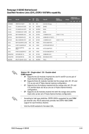
...both the orange slots and the black slots as one DIMM per channel only. Size SS/ DS Chip Brand Chip NO. Timing DIMM (BIOS) Voltage DIMM socket support (Optional) A* B* C* D* CM3X1024-1066C7 1GB DS N/A Heat-Sink Package 7 1.1 ••• ... Side(s): SS - Single-sided DS - ROG Rampage II GENE 2-21 Rampage II GENE Motherboard Qualified Vendors Lists (QVL) DDR3-1067MHz capability Vendor CORSAIR Crucial Crucial Crucial ELPIDA ELPIDA ELPIDA Hynix Hynix Hynix Hynix KINGSTON KINGSTON MICRON Part No. ASUS exclusively provides two DDR3-1600 DIMM support for each...
...both the orange slots and the black slots as one DIMM per channel only. Size SS/ DS Chip Brand Chip NO. Timing DIMM (BIOS) Voltage DIMM socket support (Optional) A* B* C* D* CM3X1024-1066C7 1GB DS N/A Heat-Sink Package 7 1.1 ••• ... Side(s): SS - Single-sided DS - ROG Rampage II GENE 2-21 Rampage II GENE Motherboard Qualified Vendors Lists (QVL) DDR3-1067MHz capability Vendor CORSAIR Crucial Crucial Crucial ELPIDA ELPIDA ELPIDA Hynix Hynix Hynix Hynix KINGSTON KINGSTON MICRON Part No. ASUS exclusively provides two DDR3-1600 DIMM support for each...
User Guide
Page 47
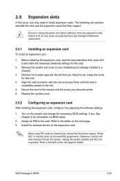
... an expansion card After installing the expansion card, configure it and make the necessary hardware settings for later use . Turn on BIOS setup. 2. Assign an IRQ to unplug the power cord before adding or removing expansion cards. Before installing the expansion card, read... making the system unstable and the card inoperable. Keep the screw for the card. 2. ROG Rampage II GENE 2-23 2.5 Expansion slots In the future, you may cause you physical injury and damage motherboard components. 2.5.1 Installing an expansion card To install an expansion card: 1. When using PCI cards...
... an expansion card After installing the expansion card, configure it and make the necessary hardware settings for later use . Turn on BIOS setup. 2. Assign an IRQ to unplug the power cord before adding or removing expansion cards. Before installing the expansion card, read... making the system unstable and the card inoperable. Keep the screw for the card. 2. ROG Rampage II GENE 2-23 2.5 Expansion slots In the future, you may cause you physical injury and damage motherboard components. 2.5.1 Installing an expansion card To install an expansion card: 1. When using PCI cards...

User Guide
Page 51
With the C.P.R. (CPU Parameter Recall) feature, shut down the clr CMOS switch on the back I /O. ROG Rampage II GENE 2-27 To erase the RTC RAM: 1. Hold down the system and clear CMOS simultaneously. If the system hangs due to overclocking of memory timing or ... jumper is moved to the Disable position, but the shutdwon function in S0 mode (DOS mode) still works. • Ensure to re-enter your previous BIOS settings after you easily clear the system setup information such as system passwords. You can automatically reset CPU parameter settings to default values. Press down...
With the C.P.R. (CPU Parameter Recall) feature, shut down the clr CMOS switch on the back I /O. ROG Rampage II GENE 2-27 To erase the RTC RAM: 1. Hold down the system and clear CMOS simultaneously. If the system hangs due to overclocking of memory timing or ... jumper is moved to the Disable position, but the shutdwon function in S0 mode (DOS mode) still works. • Ensure to re-enter your previous BIOS settings after you easily clear the system setup information such as system passwords. You can automatically reset CPU parameter settings to default values. Press down...
User Guide
Page 53
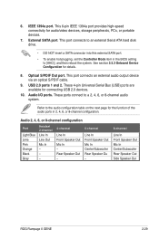
... the BIOS setting to a 2, 4, 6, or 8-channel audio system. These ports connect to [AHCI], and then reboot the system. Rear Speaker Out - 6-channel Line In Front Speaker Out Mic In Center/Subwoofer Rear Speaker Ou - 8-channel Line In Front Speaker Out Mic In Center/Subwoofer Rear Speaker Out Side Speaker Out ROG Rampage II GENE...
... the BIOS setting to a 2, 4, 6, or 8-channel audio system. These ports connect to [AHCI], and then reboot the system. Rear Speaker Out - 6-channel Line In Front Speaker Out Mic In Center/Subwoofer Rear Speaker Ou - 8-channel Line In Front Speaker Out Mic In Center/Subwoofer Rear Speaker Out Side Speaker Out ROG Rampage II GENE...
User Guide
Page 55
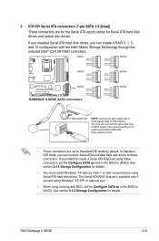
...These connectors are using Windows® XP SP1 or later version. • When using hot-plug and NCQ, set the Configure SATA as in the BIOS to [AHCI]. See section 3.4.5 Storage Configuration for details. • You must install Windows® XP Service Pack 1 or later version before using ... set using Serial ATA hard disk drives. See section 3.4.5 Storage Configuration for Serial ATA hard disk drives and optical disc drives. ROG Rampage II GENE 2-31 2. ICH10R Serial ATA connectors (7-pin SATA 1-6 [blue]) These connectors are for the Serial ATA signal cables for details.
...These connectors are using Windows® XP SP1 or later version. • When using hot-plug and NCQ, set the Configure SATA as in the BIOS to [AHCI]. See section 3.4.5 Storage Configuration for details. • You must install Windows® XP Service Pack 1 or later version before using ... set using Serial ATA hard disk drives. See section 3.4.5 Storage Configuration for Serial ATA hard disk drives and optical disc drives. ROG Rampage II GENE 2-31 2. ICH10R Serial ATA connectors (7-pin SATA 1-6 [blue]) These connectors are for the Serial ATA signal cables for details.

User Guide
Page 56
... cable to [AHCI], and then reboot the system. USB910; Doing so will damage the motherboard! To enable hot-plugging, set the Controller Mode item in the BIOS setting to the USB connectors. You can connect the USB cable to ASUS Q-Connector (USB, blue) first, and then install the Q-Connector (USB) to the USB...
... cable to [AHCI], and then reboot the system. USB910; Doing so will damage the motherboard! To enable hot-plugging, set the Controller Mode item in the BIOS setting to the USB connectors. You can connect the USB cable to ASUS Q-Connector (USB, blue) first, and then install the Q-Connector (USB) to the USB...

User Guide
Page 58
... one end of the front panel audio I /O module that you connect a high-definition front panel audio module to this connector to avail of the motherboard's high-definition audio capability. • If you want to connect a high-definition front panel audio module to this connector, set the Front Panel Type... item in the BIOS setup to [HD Audio]; By default, this connector, set to [AC97]. Front panel audio connector (10-1 pin AAFP) This connector is set ...
... one end of the front panel audio I /O module that you connect a high-definition front panel audio module to this connector to avail of the motherboard's high-definition audio capability. • If you want to connect a high-definition front panel audio module to this connector, set the Front Panel Type... item in the BIOS setup to [HD Audio]; By default, this connector, set to [AC97]. Front panel audio connector (10-1 pin AAFP) This connector is set ...

User Guide
Page 60
... "Ground" are for a chassis-mounted intrusion detection sensor or switch. 10. The optional fan1/2 can work with a jumper cap. Enable OPT FAN1/2 overheat protection in BIOS if you connect thermal sensor cables to these connectors and place the other ends to the devices which you intend to these connectors. Connect the...
... "Ground" are for a chassis-mounted intrusion detection sensor or switch. 10. The optional fan1/2 can work with a jumper cap. Enable OPT FAN1/2 overheat protection in BIOS if you connect thermal sensor cables to these connectors and place the other ends to the devices which you intend to these connectors. Connect the...


