User Guide
Page 4
Contents 2.8.3 2.8.4 2.8.5 Redundant power supply module 2-19 Installing ASUS PIKE RAID card (optional 2-20 Installing ASMB4 series management board (optional)...2-22... the server 3-4 Chapter 4: Motherboard information 4.1 Motherboard layouts 4-2 4.2 Jumpers 4-4 4.3 Internal connectors 4-9 Chapter 5: BIOS setup 5.1 Managing and updating your BIOS 5-2 5.1.1 AFUDOS utility 5-2 5.1.2 ASUS CrashFree BIOS 3 utility 5-4 5.2 BIOS setup program 5-5 5.2.1 BIOS menu screen 5-6 5.2.2 Menu bar 5-6 5.2.3 Navigation keys 5-6 5.2.4 Menu items 5-7 5.2.5 Sub-menu items 5-7 5.2.6 Configuration ...
Contents 2.8.3 2.8.4 2.8.5 Redundant power supply module 2-19 Installing ASUS PIKE RAID card (optional 2-20 Installing ASMB4 series management board (optional)...2-22... the server 3-4 Chapter 4: Motherboard information 4.1 Motherboard layouts 4-2 4.2 Jumpers 4-4 4.3 Internal connectors 4-9 Chapter 5: BIOS setup 5.1 Managing and updating your BIOS 5-2 5.1.1 AFUDOS utility 5-2 5.1.2 ASUS CrashFree BIOS 3 utility 5-4 5.2 BIOS setup program 5-5 5.2.1 BIOS menu screen 5-6 5.2.2 Menu bar 5-6 5.2.3 Navigation keys 5-6 5.2.4 Menu items 5-7 5.2.5 Sub-menu items 5-7 5.2.6 Configuration ...
User Guide
Page 8
...any additional devices to fix it by the manufacturer. viii Ask for the system unit and all the manuals included with a three-wire power cable and plug for the user's safety. Replace only with a properly grounded electrical outlet to the manufacturer's instructions. Contact a qualified service... package. • Before using the server, ensure all power cables from the existing system before you add a device. • If the power supply is broken, do not try to or from the system, ensure that the power cables for assistance when moving or carrying the system. CD...
...any additional devices to fix it by the manufacturer. viii Ask for the system unit and all the manuals included with a three-wire power cable and plug for the user's safety. Replace only with a properly grounded electrical outlet to the manufacturer's instructions. Contact a qualified service... package. • Before using the server, ensure all power cables from the existing system before you add a device. • If the power supply is broken, do not try to or from the system, ensure that the power cables for assistance when moving or carrying the system. CD...

User Guide
Page 12
... for the following items. Model Name Chassis RS520-E6/RS8 ASUS R20A 2U Rackmount Chassis Motherboard ASUS Z8NR-D12-SYS Server Board Component 1 x 770W Redundant Power Supply 1 x SATAII/SAS HDD Backplane (BP8LX-R20A) 8 x hot-swap HDD trays (varies by territories) 1 x Front I/O Board (FPB-AR14) 4 x System Fans (80 x 38mm) 1 x Redundant Power Supply Distribution Board (PSB-R12A) 1 x Air Duct 1 x PCI...
... for the following items. Model Name Chassis RS520-E6/RS8 ASUS R20A 2U Rackmount Chassis Motherboard ASUS Z8NR-D12-SYS Server Board Component 1 x 770W Redundant Power Supply 1 x SATAII/SAS HDD Backplane (BP8LX-R20A) 8 x hot-swap HDD trays (varies by territories) 1 x Front I/O Board (FPB-AR14) 4 x System Fans (80 x 38mm) 1 x Redundant Power Supply Distribution Board (PSB-R12A) 1 x Air Duct 1 x PCI...
User Guide
Page 14
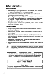
... Out of Band Management Remote Solution Hardware Software Dimension (HH x WW x DD) Net Weight Kg (CPU, DRAM & HDD not inclu ded) Power Supply Environment 2 x Intel® 82574L PCI-E GbE LANs Aspeed AST2050 / 8MB 1 x Slim-type Optical Device Bay Options: No Device / DVD-...anti-virus software (Optional) Onboard IPMI Solution ASMB4-iKVM for KVM-over-IP support (Optional) ASUS ASWM 2.0 and SNMP® 615mm x 444mm x 87mm 22 Kg 770W (80+) 1+1 Redundant Power Supply (Default with one Power Supply Module) Operation temperature: 10°C ~ 35°C / Non operation temperature: -40&#...
... Out of Band Management Remote Solution Hardware Software Dimension (HH x WW x DD) Net Weight Kg (CPU, DRAM & HDD not inclu ded) Power Supply Environment 2 x Intel® 82574L PCI-E GbE LANs Aspeed AST2050 / 8MB 1 x Slim-type Optical Device Bay Options: No Device / DVD-...anti-virus software (Optional) Onboard IPMI Solution ASMB4-iKVM for KVM-over-IP support (Optional) ASUS ASWM 2.0 and SNMP® 615mm x 444mm x 87mm 22 Kg 770W (80+) 1+1 Redundant Power Supply (Default with one Power Supply Module) Operation temperature: 10°C ~ 35°C / Non operation temperature: -40&#...

User Guide
Page 15
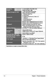
... 5 HDD 2 HDD 6 HDD 3 HDD 7 HDD 4 HDD 8 1.5 Rear panel features The rear panel includes the expansion slots, system power socket, and rear fans. ASUS RS520-E6/RS8 1-5 The power and reset buttons, LED indicators, optical drive, and two USB ports are located on the rear panel if motherboard is not present. •... 3 Expansion slots LAN port 2 LAN port 1 VGA port Serial port USB ports LAN port 3* PS/2 keyboard port PS/2 mouse port Power cord connector Redundant power supply dummy cover • The ports for the PS/2 keyboard, PS/2 mouse, USB, VGA, and Gigabit LAN do not appear on the front...
... 5 HDD 2 HDD 6 HDD 3 HDD 7 HDD 4 HDD 8 1.5 Rear panel features The rear panel includes the expansion slots, system power socket, and rear fans. ASUS RS520-E6/RS8 1-5 The power and reset buttons, LED indicators, optical drive, and two USB ports are located on the rear panel if motherboard is not present. •... 3 Expansion slots LAN port 2 LAN port 1 VGA port Serial port USB ports LAN port 3* PS/2 keyboard port PS/2 mouse port Power cord connector Redundant power supply dummy cover • The ports for the PS/2 keyboard, PS/2 mouse, USB, VGA, and Gigabit LAN do not appear on the front...
User Guide
Page 16
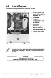
...or rear panel if you need to use a floppy disk. *WARNING HAZARDOUS MOVING PARTS KEEP FINGERS AND OTHER BODY PARTS AWAY 1-6 Chapter 1: Product introduction Power supply 4 2 3. System fans* 6. SATA/SAS backplane 7. Hot-swap HDD trays 5 5 5 5 8. Slim-type optical drive bay 9. Front I/O ...board (hidden) 6 7 8 9 The barebone server does not include a floppy disk drive. ASUS Z8NR-D12-SYS server board 5. Power fans 4. 1.6 Internal features The barebone server includes the basic components as shown. 1. 2 x PCI-E x8 slot (at x8 link)+...
...or rear panel if you need to use a floppy disk. *WARNING HAZARDOUS MOVING PARTS KEEP FINGERS AND OTHER BODY PARTS AWAY 1-6 Chapter 1: Product introduction Power supply 4 2 3. System fans* 6. SATA/SAS backplane 7. Hot-swap HDD trays 5 5 5 5 8. Slim-type optical drive bay 9. Front I/O ...board (hidden) 6 7 8 9 The barebone server does not include a floppy disk drive. ASUS Z8NR-D12-SYS server board 5. Power fans 4. 1.6 Internal features The barebone server includes the basic components as shown. 1. 2 x PCI-E x8 slot (at x8 link)+...

User Guide
Page 27
... A DIMM is properly seated. ASUS RS520-E6/RS8 2-9 Align a DIMM on the socket such that it flips out with extra force. 2. Remove the DIMM from the socket. Locked Retaining Clip 2.3.4 Removing a DIMM Follow these steps to avoid damaging the DIMM. 3. Simultaneously press the retaining clips outward to unplug the power supply before adding or removing...
... A DIMM is properly seated. ASUS RS520-E6/RS8 2-9 Align a DIMM on the socket such that it flips out with extra force. 2. Remove the DIMM from the socket. Locked Retaining Clip 2.3.4 Removing a DIMM Follow these steps to avoid damaging the DIMM. 3. Simultaneously press the retaining clips outward to unplug the power supply before adding or removing...
User Guide
Page 32
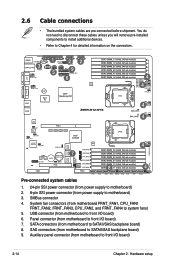
...; Refer to Chapter 4 for detailed information on the connectors. 1 3 5 22 9 6 4 4 4 4 4 7 8 4 Pre-connected system cables 1. 24-pin SSI power connector (from power supply to motherboard) 2. 8-pin SSI power connector (from motherboard to front I /O board) 7. SAS connectors (from power supply to SATAII/SAS backplane board) 8. SMBus connector 4. 2.6 Cable connections • The bundled system cables are pre-connected before...
...; Refer to Chapter 4 for detailed information on the connectors. 1 3 5 22 9 6 4 4 4 4 4 7 8 4 Pre-connected system cables 1. 24-pin SSI power connector (from power supply to motherboard) 2. 8-pin SSI power connector (from motherboard to front I /O board) 7. SAS connectors (from power supply to SATAII/SAS backplane board) 8. SMBus connector 4. 2.6 Cable connections • The bundled system cables are pre-connected before...

User Guide
Page 33
2.7 SATAII/SAS backplane cabling Connects a 8-pin plug from power supply Connects the data cables connected to the motherboard SGPIO_SEL jumper: pins 1-2 (Onboard) pins 2-3 (Add-on card) ASUS RS520-E6/RS8 2-15
2.7 SATAII/SAS backplane cabling Connects a 8-pin plug from power supply Connects the data cables connected to the motherboard SGPIO_SEL jumper: pins 1-2 (Onboard) pins 2-3 (Add-on card) ASUS RS520-E6/RS8 2-15
User Guide
Page 34
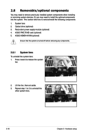
... the system is turned off before removing any components. 2.8.1 System fans To uninstall the system fans: 1. Lift the fan, then set aside. 3. ASUS PIKE RAID card (optional) 5. Redundant power supply module (optional) 4. This section tells how to remove/install the following components: 1. 2.8 Removable/optional components You may need to remove previously installed system...
... the system is turned off before removing any components. 2.8.1 System fans To uninstall the system fans: 1. Lift the fan, then set aside. 3. ASUS PIKE RAID card (optional) 5. Redundant power supply module (optional) 4. This section tells how to remove/install the following components: 1. 2.8 Removable/optional components You may need to remove previously installed system...

User Guide
Page 37
Take out the seocond redundant power supply module from its package. 2.8.3 Redundant power supply module To install a second redundant power supply module: 1. Slide it into the chassis. Remove the redundant power supply dummy cover. 2. Firmly pull the lever to slide the power supply module into the chassis. 3. ASUS RS520-E6/RS8 2-19
Take out the seocond redundant power supply module from its package. 2.8.3 Redundant power supply module To install a second redundant power supply module: 1. Slide it into the chassis. Remove the redundant power supply dummy cover. 2. Firmly pull the lever to slide the power supply module into the chassis. 3. ASUS RS520-E6/RS8 2-19

User Guide
Page 47
... RECOVERY1) 7. Serial General Purpose Input/Output connectors (8-1 pin SGPIO2/3) 6. Power supply SMBus connector (5-pin PSUSMB1) 10. Serial ATA connectors (7-pin SATA1-4 [red], SATA5-6 [black]) 2. Auxiliary panel connector (20-pin AUX_PANEL1 [black]) Page 4-9 4-9 4-10 4-10 4-11 4-11 4-12 4-12 4-13 4-13 4-14 4-15 4-16 ASUS RS520-E6/RS8 4-3 LAN controller setting (3-pin LAN_SW1, LAN_SW2) 4. RAID configuration...
... RECOVERY1) 7. Serial General Purpose Input/Output connectors (8-1 pin SGPIO2/3) 6. Power supply SMBus connector (5-pin PSUSMB1) 10. Serial ATA connectors (7-pin SATA1-4 [red], SATA5-6 [black]) 2. Auxiliary panel connector (20-pin AUX_PANEL1 [black]) Page 4-9 4-9 4-10 4-10 4-11 4-11 4-12 4-12 4-13 4-13 4-14 4-15 4-16 ASUS RS520-E6/RS8 4-3 LAN controller setting (3-pin LAN_SW1, LAN_SW2) 4. RAID configuration...
User Guide
Page 57
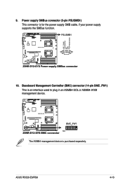
The ASMB4 management device is for the power supply SMB cable, if your power supply supports the SMBus function. 10. ASUS RS520-E6/RS8 4-13 9. Power supply SMBus connector (5-pin PSUSMB1) This connector is purchased separately. Baseboard Management Controller (BMC) connector (14-pin BMC_FW1) This is an interface used to plug in an ASMB4-SOL or ASMB4-iKVM management device.
The ASMB4 management device is for the power supply SMB cable, if your power supply supports the SMBus function. 10. ASUS RS520-E6/RS8 4-13 9. Power supply SMBus connector (5-pin PSUSMB1) This connector is purchased separately. Baseboard Management Controller (BMC) connector (14-pin BMC_FW1) This is an interface used to plug in an ASMB4-SOL or ASMB4-iKVM management device.

User Guide
Page 58
... not boot up if the power is recommended when configuring a system with a higher power rating if you use an SSI 12 V-compliant power supply unit (PSU) for SSI power supply plugs. 11. The power supply plugs are for LGA1366‑socket Intel® Xeon processors. • DO NOT forget to connect the 24+8+8-pin power plugs; The system may...
... not boot up if the power is recommended when configuring a system with a higher power rating if you use an SSI 12 V-compliant power supply unit (PSU) for SSI power supply plugs. 11. The power supply plugs are for LGA1366‑socket Intel® Xeon processors. • DO NOT forget to connect the 24+8+8-pin power plugs; The system may...


