
User Guide
Page 11
ASUS RS520-E6/RS8 1- Product introduction Chapter 1 This chapter describes the general features of the chassis kit. It includes sections on front panel and rear panel specifications.
ASUS RS520-E6/RS8 1- Product introduction Chapter 1 This chapter describes the general features of the chassis kit. It includes sections on front panel and rear panel specifications.

User Guide
Page 12
1.1 System package contents Check your system package for the following items. Model Name Chassis RS520-E6/RS8 ASUS R20A 2U Rackmount Chassis Motherboard ASUS Z8NR-D12-SYS Server Board Component 1 x 770W Redundant Power Supply 1 x SATAII/SAS HDD Backplane (BP8LX-R20A) 8 x hot-swap HDD trays (varies by territories) 1 x Front I/O Board (...
1.1 System package contents Check your system package for the following items. Model Name Chassis RS520-E6/RS8 ASUS R20A 2U Rackmount Chassis Motherboard ASUS Z8NR-D12-SYS Server Board Component 1 x 770W Redundant Power Supply 1 x SATAII/SAS HDD Backplane (BP8LX-R20A) 8 x hot-swap HDD trays (varies by territories) 1 x Front I/O Board (...

User Guide
Page 13
... 8-port SAS RAID card - Supports software RAID 0, 1 & 10 Optional: ASUS PIKE 1068E 8-port SAS RAID card - 1.3 System specifications The ASUS RS520-E6/RS8 is a server featuring the ASUS Z8NR-D12-SYS server board. Supports software RAID 0, 1, 5 & 10 LSI MegaRAID (for Windows only) - Model Name Processor / System Bus RS520-E6/RS8 2 x Socket LGA1366 Intel® Xeon® 5500 series processors...
... 8-port SAS RAID card - Supports software RAID 0, 1 & 10 Optional: ASUS PIKE 1068E 8-port SAS RAID card - 1.3 System specifications The ASUS RS520-E6/RS8 is a server featuring the ASUS Z8NR-D12-SYS server board. Supports software RAID 0, 1, 5 & 10 LSI MegaRAID (for Windows only) - Model Name Processor / System Bus RS520-E6/RS8 2 x Socket LGA1366 Intel® Xeon® 5500 series processors...

User Guide
Page 15
... buttons, LED indicators, optical drive, and two USB ports are located on the rear panel if motherboard is not present. • *The port is for ASUS ASMB4-iKVM controller card only. 1.4 Front panel features The barebone server displays a simple yet stylish front panel with openings for the rear panel connectors on... button HDD 1 HDD 5 HDD 2 HDD 6 HDD 3 HDD 7 HDD 4 HDD 8 1.5 Rear panel features The rear panel includes the expansion slots, system power socket, and rear fans. ASUS RS520-E6/RS8 1-5
... buttons, LED indicators, optical drive, and two USB ports are located on the rear panel if motherboard is not present. • *The port is for ASUS ASMB4-iKVM controller card only. 1.4 Front panel features The barebone server displays a simple yet stylish front panel with openings for the rear panel connectors on... button HDD 1 HDD 5 HDD 2 HDD 6 HDD 3 HDD 7 HDD 4 HDD 8 1.5 Rear panel features The rear panel includes the expansion slots, system power socket, and rear fans. ASUS RS520-E6/RS8 1-5

User Guide
Page 17
... Status Description OFF No link GREEN Linked BLINKING Data activity SPEED LED Status Description OFF 10 Mbps connection ORANGE 100 Mbps connection GREEN 1 Gbps connection ASUS RS520-E6/RS8 1-7
... Status Description OFF No link GREEN Linked BLINKING Data activity SPEED LED Status Description OFF 10 Mbps connection ORANGE 100 Mbps connection GREEN 1 Gbps connection ASUS RS520-E6/RS8 1-7

User Guide
Page 19
Hardware setup Chapter 2 This chapter lists the hardware setup procedures that you have to perform when installing or removing system components. ASUS RS520-E6/RS8 2-
Hardware setup Chapter 2 This chapter lists the hardware setup procedures that you have to perform when installing or removing system components. ASUS RS520-E6/RS8 2-

User Guide
Page 21
...the damage is on the LGA1366 socket. • The product warranty does not cover damage to the PnP cap/socket contacts/motherboard components. ASUS will shoulder the cost of the PnP cap. 2.2.1 Installing the CPU To install a CPU: 1. Locate the CPU socket on your ...installing the CPU, ensure that the PnP cap is shipment/transit-related. • Keep the cap after installing the motherboard. Contact your left. ASUS RS520-E6/RS8 2-3 2.2 Central Processing Unit (CPU) The motherboard comes with two surface mount LGA1366 sockets designed for the Intel® Xeon® Dual/Quad ...
...the damage is on the LGA1366 socket. • The product warranty does not cover damage to the PnP cap/socket contacts/motherboard components. ASUS will shoulder the cost of the PnP cap. 2.2.1 Installing the CPU To install a CPU: 1. Locate the CPU socket on your ...installing the CPU, ensure that the PnP cap is shipment/transit-related. • Keep the cap after installing the motherboard. Contact your left. ASUS RS520-E6/RS8 2-3 2.2 Central Processing Unit (CPU) The motherboard comes with two surface mount LGA1366 sockets designed for the Intel® Xeon® Dual/Quad ...

User Guide
Page 23
..., ensuring that you wash it off immediately and seek professional medical help. DO NOT force the CPU into your eyes or touches your finger directly. 8. A ASUS RS520-E6/RS8 B 2-5 CPU notch Alignment key Gold triangle mark 7. To prevent contaminating the paste, DO NOT spread the paste with preapplied thermal paste. If it gets into...
..., ensuring that you wash it off immediately and seek professional medical help. DO NOT force the CPU into your eyes or touches your finger directly. 8. A ASUS RS520-E6/RS8 B 2-5 CPU notch Alignment key Gold triangle mark 7. To prevent contaminating the paste, DO NOT spread the paste with preapplied thermal paste. If it gets into...

User Guide
Page 25
... boot if only one DIMM is installed in DIMM slot A2, B2, or C2 for CPU1, or D2, E2 or F2 for recommended memory configuration. ASUS RS520-E6/RS8 2-7
... boot if only one DIMM is installed in DIMM slot A2, B2, or C2 for CPU1, or D2, E2 or F2 for recommended memory configuration. ASUS RS520-E6/RS8 2-7

User Guide
Page 27
... to remove a DIMM. 2 1. Failure to do so may cause severe damage to unplug the power supply before adding or removing DIMMs or other system components. ASUS RS520-E6/RS8 2-9 Unlock a DIMM socket by pressing the retaining clips outward. 2. The DIMM might get damaged when it fits in place and the DIMM is keyed with...
... to remove a DIMM. 2 1. Failure to do so may cause severe damage to unplug the power supply before adding or removing DIMMs or other system components. ASUS RS520-E6/RS8 2-9 Unlock a DIMM socket by pressing the retaining clips outward. 2. The DIMM might get damaged when it fits in place and the DIMM is keyed with...

User Guide
Page 29
ASUS RS520-E6/RS8 2-11 When installed, the SATAII/SAS connector on the backplane. 6. Repeat steps 1 to 6 if you wish to the SATAII/ SAS interface on the drive connects to install a second SATAII/SAS drive. Carefully insert the drive tray and push it all the way to the depth of the tray edge protrudes. Push the tray lever until just a small fraction of the bay until it clicks, and secures the drive tray in place. The drive tray is correctly placed when its front edge aligns with the bay edge. 7. 5.
ASUS RS520-E6/RS8 2-11 When installed, the SATAII/SAS connector on the backplane. 6. Repeat steps 1 to 6 if you wish to the SATAII/ SAS interface on the drive connects to install a second SATAII/SAS drive. Carefully insert the drive tray and push it all the way to the depth of the tray edge protrudes. Push the tray lever until just a small fraction of the bay until it clicks, and secures the drive tray in place. The drive tray is correctly placed when its front edge aligns with the bay edge. 7. 5.
User Guide
Page 31
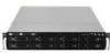
Refer to the card. ASUS RS520-E6/RS8 2-13 Turn on BIOS setup. 2. Assign an IRQ to the following tables. 3. Install the software drivers for ISA or PCI devices. Standard Interrupt assignments IRQ ...
Refer to the card. ASUS RS520-E6/RS8 2-13 Turn on BIOS setup. 2. Assign an IRQ to the following tables. 3. Install the software drivers for ISA or PCI devices. Standard Interrupt assignments IRQ ...

User Guide
Page 33
2.7 SATAII/SAS backplane cabling Connects a 8-pin plug from power supply Connects the data cables connected to the motherboard SGPIO_SEL jumper: pins 1-2 (Onboard) pins 2-3 (Add-on card) ASUS RS520-E6/RS8 2-15
2.7 SATAII/SAS backplane cabling Connects a 8-pin plug from power supply Connects the data cables connected to the motherboard SGPIO_SEL jumper: pins 1-2 (Onboard) pins 2-3 (Add-on card) ASUS RS520-E6/RS8 2-15

User Guide
Page 35
Push the slim optical drive all the way to release the dummy covor for the optical drive bay. 2. Insert the slim optical drive into the drive bay. 4. ASUS RS520-E6/RS8 2-17 2.8.2 Optical drive (optional) To install the slim optical drive: 1. Take out the optional optical drive from its package. Remove the two screws to the depth of the bay until it with four screws. 3. Place it in the optical dirve tray, and then secure it clicks in place.
Push the slim optical drive all the way to release the dummy covor for the optical drive bay. 2. Insert the slim optical drive into the drive bay. 4. ASUS RS520-E6/RS8 2-17 2.8.2 Optical drive (optional) To install the slim optical drive: 1. Take out the optional optical drive from its package. Remove the two screws to the depth of the bay until it with four screws. 3. Place it in the optical dirve tray, and then secure it clicks in place.

User Guide
Page 37
Remove the redundant power supply dummy cover. 2. Slide it into the chassis. ASUS RS520-E6/RS8 2-19 Take out the seocond redundant power supply module from its package. 2.8.3 Redundant power supply module To install a second redundant power supply module: 1. Firmly pull the lever to slide the power supply module into the chassis. 3.
Remove the redundant power supply dummy cover. 2. Slide it into the chassis. ASUS RS520-E6/RS8 2-19 Take out the seocond redundant power supply module from its package. 2.8.3 Redundant power supply module To install a second redundant power supply module: 1. Firmly pull the lever to slide the power supply module into the chassis. 3.

User Guide
Page 39
Connect the data cables, by numerial order, to the SAS connectors labeled SAS1-4 (red) on the motherboard. Set the SGPIO_SEL1 jumper on the backplane to pin 2-3 when connecting data cables to install an optional i Button on the motherboard. 2. ASUS RS520-E6/RS8 2-21 Snap the I Button slot on your motherboard. 1. 5. Locate the I Button in place. Installing i Button (for PIKE 1078 only) Follow the steps below to the SAS connectors on the motherboard. 6.
Connect the data cables, by numerial order, to the SAS connectors labeled SAS1-4 (red) on the motherboard. Set the SGPIO_SEL1 jumper on the backplane to pin 2-3 when connecting data cables to install an optional i Button on the motherboard. 2. ASUS RS520-E6/RS8 2-21 Snap the I Button slot on your motherboard. 1. 5. Locate the I Button in place. Installing i Button (for PIKE 1078 only) Follow the steps below to the SAS connectors on the motherboard. 6.

User Guide
Page 41
ASUS RS520-E6/RS8 2- Installation options Chapter 3 This chapter describes how to install the optional components and devices into the barebone server.
ASUS RS520-E6/RS8 2- Installation options Chapter 3 This chapter describes how to install the optional components and devices into the barebone server.

User Guide
Page 43
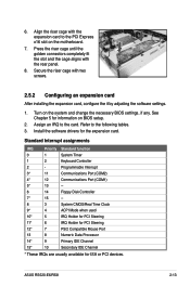
... rails To attach the rack rails: 1. Then slide the rail toward the front panel until it fits the rack. 6. Ensure that it locks in place. 4. ASUS RS520-E6/RS8 3-3 Position the rack rail to determine the length of the rack to the 2U space on the rail. Secure the rear end of the 2U...
... rails To attach the rack rails: 1. Then slide the rail toward the front panel until it fits the rack. 6. Ensure that it locks in place. 4. ASUS RS520-E6/RS8 3-3 Position the rack rail to determine the length of the rack to the 2U space on the rail. Secure the rear end of the 2U...

User Guide
Page 45
ASUS RS520-E6/RS8 3- 4-1 Motherboard info Chapter 4 This chapter includes the motherboard layout, and brief descriptions of the jumpers and internal connectors.
ASUS RS520-E6/RS8 3- 4-1 Motherboard info Chapter 4 This chapter includes the motherboard layout, and brief descriptions of the jumpers and internal connectors.

User Guide
Page 47
...Serial port connectors (10-1 pin COM2) 9. Auxiliary panel connector (20-pin AUX_PANEL1 [black]) Page 4-9 4-9 4-10 4-10 4-11 4-11 4-12 4-12 4-13 4-13 4-14 4-15 4-16 ASUS RS520-E6/RS8 4-3 SAS connectors (7-pin SAS1-4 [red], SAS5-8 [blue]) 3. USB connectors (10-1 pin USB34, USB56; 4-pin USB7) 7. SSI power connectors (24-pin ATXPWR1, 8-pin ATX12V1/2) 12.... CPU_FAN1/2, REAR_FAN1/2, FRNT_FAN1/2/3/4) 8. Serial General Purpose Input/Output connectors (8-1 pin SGPIO2/3) 6. Baseboard Management Controller (BMC) connector (14-pin BMC_FW1) 11. Clear RTC RAM (CLRTC1) 2.
...Serial port connectors (10-1 pin COM2) 9. Auxiliary panel connector (20-pin AUX_PANEL1 [black]) Page 4-9 4-9 4-10 4-10 4-11 4-11 4-12 4-12 4-13 4-13 4-14 4-15 4-16 ASUS RS520-E6/RS8 4-3 SAS connectors (7-pin SAS1-4 [red], SAS5-8 [blue]) 3. USB connectors (10-1 pin USB34, USB56; 4-pin USB7) 7. SSI power connectors (24-pin ATXPWR1, 8-pin ATX12V1/2) 12.... CPU_FAN1/2, REAR_FAN1/2, FRNT_FAN1/2/3/4) 8. Serial General Purpose Input/Output connectors (8-1 pin SGPIO2/3) 6. Baseboard Management Controller (BMC) connector (14-pin BMC_FW1) 11. Clear RTC RAM (CLRTC1) 2.