
User Manual
Page 15
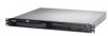
1.4 Front panel features The barebone server displays a simple yet stylish front panel with openings for the rear panel connectors on the motherboard are located on the rear panel if motherboard is not present. • *The port is for the LED descriptions. ASUS RS100-E6/PI2 1-5 Expansion slot LAN port 1 LAN ... indicators, optical drive, and twp USB ports are also placed in the rear panel. Refer to section 1.7.1 Front panel LEDs for ASUS ASMB4-iKVM controller card only. USB 2.0 ports Optical drive HDD Access LED LAN2 LED LAN1 LED Power LED Power button Reset button Turn...
1.4 Front panel features The barebone server displays a simple yet stylish front panel with openings for the rear panel connectors on the motherboard are located on the rear panel if motherboard is not present. • *The port is for the LED descriptions. ASUS RS100-E6/PI2 1-5 Expansion slot LAN port 1 LAN ... indicators, optical drive, and twp USB ports are also placed in the rear panel. Refer to section 1.7.1 Front panel LEDs for ASUS ASMB4-iKVM controller card only. USB 2.0 ports Optical drive HDD Access LED LAN2 LED LAN1 LED Power LED Power button Reset button Turn...
User Manual
Page 17
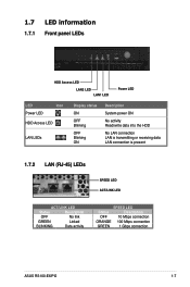
1.7 LED information 1.7.1 Front panel LEDs HDD Access LED LAN2 LED LAN1 LED Power LED LED Icon Power LED HDD Access LED LAN LEDs Display status ON OFF Blinking OFF Blinking ON Description System power ON No activity Read/write data into the HDD No LAN connection LAN is transmitting ... Status Description OFF No link GREEN Linked BLINKING Data activity SPEED LED Status Description OFF 10 Mbps connection ORANGE 100 Mbps connection GREEN 1 Gbps connection ASUS RS100-E6/PI2 1-7
1.7 LED information 1.7.1 Front panel LEDs HDD Access LED LAN2 LED LAN1 LED Power LED LED Icon Power LED HDD Access LED LAN LEDs Display status ON OFF Blinking OFF Blinking ON Description System power ON No activity Read/write data into the HDD No LAN connection LAN is transmitting ... Status Description OFF No link GREEN Linked BLINKING Data activity SPEED LED Status Description OFF 10 Mbps connection ORANGE 100 Mbps connection GREEN 1 Gbps connection ASUS RS100-E6/PI2 1-7

User Manual
Page 63
...failure! Boot the system in DOS environment using the BUPDATER utility: 1. A:\>BUPDATER /i[file name].ROM ASUS RS100-E6/PI2 5-3 3. When found . Copy the BUPDATER utility (BUPDATER.exe) from the ASUS support website at www.asus.com and download the latest BIOS file for reference only. Press to a bootable USB flash disk ...drive you to ensure system compatibility and stability. Select the Load Setup Defaults item under the Exit menu. The actual BIOS screen displays may not be the same as a USB flash disk with the updated BIOS file. Save the BIOS file to switch between ...
...failure! Boot the system in DOS environment using the BUPDATER utility: 1. A:\>BUPDATER /i[file name].ROM ASUS RS100-E6/PI2 5-3 3. When found . Copy the BUPDATER utility (BUPDATER.exe) from the ASUS support website at www.asus.com and download the latest BIOS file for reference only. Press to a bootable USB flash disk ...drive you to ensure system compatibility and stability. Select the Load Setup Defaults item under the Exit menu. The actual BIOS screen displays may not be the same as a USB flash disk with the updated BIOS file. Save the BIOS file to switch between ...

User Manual
Page 68
... item on any menu screen means that menu; Refer to 5.2.7 Pop-up window. 5.2.7 Pop-up window Select a menu item and press to display available options. To display the sub-menu, select the item and press . 5.2.6 Configuration fields These fields show the values for the menu items. If an item is ...a brief description of a field, select it then press to display a pop-up window Scroll bar At the top right corner of the menu screen is user-configurable, you can change the value of the selected...
... item on any menu screen means that menu; Refer to 5.2.7 Pop-up window. 5.2.7 Pop-up window Select a menu item and press to display available options. To display the sub-menu, select the item and press . 5.2.6 Configuration fields These fields show the values for the menu items. If an item is ...a brief description of a field, select it then press to display a pop-up window Scroll bar At the top right corner of the menu screen is user-configurable, you can change the value of the selected...

User Manual
Page 69
.... ASUS RS100-E6/PI2 5-9 Main Advanced BIOS SETUP UTILITY Server Power Boot Tools Exit System Time [13:44:30] System Date [Tue, 09/22/2009] SATA 1 SATA 2 SATA 3 SATA 4 SATA 5 SATA 6 : [ST3160812AS] : [Not Detected] : [Not Detected] : [Not Detected] : [Not Detected] : [Not Detected] Storage Configuration System Information Use [ENTER], [TAB] or [SHIFT-TAB] to display the...
.... ASUS RS100-E6/PI2 5-9 Main Advanced BIOS SETUP UTILITY Server Power Boot Tools Exit System Time [13:44:30] System Date [Tue, 09/22/2009] SATA 1 SATA 2 SATA 3 SATA 4 SATA 5 SATA 6 : [ST3160812AS] : [Not Detected] : [Not Detected] : [Not Detected] : [Not Detected] : [Not Detected] Storage Configuration System Information Use [ENTER], [TAB] or [SHIFT-TAB] to display the...

User Manual
Page 72
... Detected] SATA Port6 [Not Detected] Some SATA CD/DVD in AHCI mode need to set the Self-Monitoring, Analysis and Reporting Technology. SATA Port1-6 [XXXX] Displays the status of auto-detection of device connected to the system. Configuration options: [Disabled] [Enabled] 5-12 Chapter 5: BIOS setup Configuration options: [Auto] [Not Installed] SMART...
... Detected] SATA Port6 [Not Detected] Some SATA CD/DVD in AHCI mode need to set the Self-Monitoring, Analysis and Reporting Technology. SATA Port1-6 [XXXX] Displays the status of auto-detection of device connected to the system. Configuration options: [Disabled] [Enabled] 5-12 Chapter 5: BIOS setup Configuration options: [Auto] [Not Installed] SMART...

User Manual
Page 73
... auto-detected system memory. Processor Displays the auto-detected CPU specification. System Memory Information Displays system memory information. BIOS Information Displays the auto-detected BIOS information. Main System Memory Information Speed DDR3 1067 BIOS SETUP UTILITY DIMM_A1 DIMM_A2 DIMM_B1 DIMM_B2 1024 MB, 1R, 1067 N/A N/A N/A ASUS RS100-E6/PI2 5-13 5.3.6 System Information This menu gives you an overview...
... auto-detected system memory. Processor Displays the auto-detected CPU specification. System Memory Information Displays system memory information. BIOS Information Displays the auto-detected BIOS information. Main System Memory Information Speed DDR3 1067 BIOS SETUP UTILITY DIMM_A1 DIMM_A2 DIMM_B1 DIMM_B2 1024 MB, 1R, 1067 N/A N/A N/A ASUS RS100-E6/PI2 5-13 5.3.6 System Information This menu gives you an overview...

User Manual
Page 78
...via SPD or designate a specific frequency. Configuration options: [Auto] [800 MHz] [1066 MHz] [1333 MHz] Refer to display the sub-menu. Memory Remap Feature [Enabled] Setting this item to [Enabled] allows you to remapp the overlapped PCI memory ...Margin Ranks [Disabled] MReCmoSreyriFarleqDuebnucgy Messa ge Level [DAiustaob]led] Memory Mode [Independent] Demand Scrubbing [Disabled] MPeamtorroyl ESCcCruFbubnicntgi on ASUS website at www.asus.com. 5-18 Chapter 5: BIOS setup Configure North Bridge features. Uncore Configuration ←→ Select Screen ↑↓ Select...
...via SPD or designate a specific frequency. Configuration options: [Auto] [800 MHz] [1066 MHz] [1333 MHz] Refer to display the sub-menu. Memory Remap Feature [Enabled] Setting this item to [Enabled] allows you to remapp the overlapped PCI memory ...Margin Ranks [Disabled] MReCmoSreyriFarleqDuebnucgy Messa ge Level [DAiustaob]led] Memory Mode [Independent] Demand Scrubbing [Disabled] MPeamtorroyl ESCcCruFbubnicntgi on ASUS website at www.asus.com. 5-18 Chapter 5: BIOS setup Configure North Bridge features. Uncore Configuration ←→ Select Screen ↑↓ Select...

User Manual
Page 86
... Boot Tools Exit Remote Access Configuration IPMI configuration including server monitoring and event log. ←→ Select Screen ↑↓ Select Item Enter Go to display the configuration options. Select an item then press to Sub Screen F1 General Help F10 Save and Exit ESC Exit v02.61 (C)Copyright 1985-2009...
... Boot Tools Exit Remote Access Configuration IPMI configuration including server monitoring and event log. ←→ Select Screen ↑↓ Select Item Enter Go to display the configuration options. Select an item then press to Sub Screen F1 General Help F10 Save and Exit ESC Exit v02.61 (C)Copyright 1985-2009...

User Manual
Page 90
... do not wish to configure the ASUS Smart Fan feature that smartly adjusts the fan speeds for the RS100-E6/PI2 server is not connected to detect this item. 5-30 Chapter 5: BIOS setup CPU1/MB1/TR1 Temperature [xxxºC/xxxºF] The onboard hardware monitor automatically detects and displays the motherboard component and CPU temperatures...
... do not wish to configure the ASUS Smart Fan feature that smartly adjusts the fan speeds for the RS100-E6/PI2 server is not connected to detect this item. 5-30 Chapter 5: BIOS setup CPU1/MB1/TR1 Temperature [xxxºC/xxxºF] The onboard hardware monitor automatically detects and displays the motherboard component and CPU temperatures...

User Manual
Page 91
... Priority sequence. The number of device items that appears on the screen depends on the number of the hard disk drives or the optical drives. ASUS RS100-E6/PI2 5-31 Configuration options: [xxxxx Drive] [Disabled] 5.7.2 Hard Disk Drives; These items allows you set the CD-ROM drive as the first boot ...; Select Item +- CDROM Drives These two items appear only when you install more than two hard disk drives or optical drives to you to display the sub-menu. 5.7 Boot menu The Boot menu items allow you system. A device enclosed in parenthesis has been disabled in the system. ...
... Priority sequence. The number of device items that appears on the screen depends on the number of the hard disk drives or the optical drives. ASUS RS100-E6/PI2 5-31 Configuration options: [xxxxx Drive] [Disabled] 5.7.2 Hard Disk Drives; These items allows you set the CD-ROM drive as the first boot ...; Select Item +- CDROM Drives These two items appear only when you install more than two hard disk drives or optical drives to you to display the sub-menu. 5.7 Boot menu The Boot menu items allow you system. A device enclosed in parenthesis has been disabled in the system. ...

User Manual
Page 92
...Num-Lock [On] Allows you to be pressed when error occurs. When set to [Enabled], the system displays the message "Press DEL to use the ASUS MyLogo2™ feature. 5.7.3 Boot Settings Configuration BIOS SETUP UTILITY Boot Boot Settings Configuration Quick Boot Full Screen ...Logo AddOn ROM Display Mode Bootup Num-Lock Wait For 'F1' If Error Hit 'DEL' Message Display [Enabled] [Disabled] [Force BIOS]...
...Num-Lock [On] Allows you to be pressed when error occurs. When set to [Enabled], the system displays the message "Press DEL to use the ASUS MyLogo2™ feature. 5.7.3 Boot Settings Configuration BIOS SETUP UTILITY Boot Boot Settings Configuration Quick Boot Full Screen ...Logo AddOn ROM Display Mode Bootup Num-Lock Wait For 'F1' If Error Hit 'DEL' Message Display [Enabled] [Disabled] [Force BIOS]...

User Manual
Page 93
.... The message "Password Installed" appears after you successfully set a password, this item to change the system security settings. If you forget your password. again to display the configuration options. Confirm the password when prompted. To clear the supervisor password, select the Change Supervisor Password then press . Select an item then press... least six letters and/or numbers, then press . 3. To change the supervisor password. 5.7.4 Security The Security menu items allow you to erase the RTC RAM. ASUS RS100-E6/PI2 5-33
.... The message "Password Installed" appears after you successfully set a password, this item to change the system security settings. If you forget your password. again to display the configuration options. Confirm the password when prompted. To clear the supervisor password, select the Change Supervisor Password then press . Select an item then press... least six letters and/or numbers, then press . 3. To change the supervisor password. 5.7.4 Security The Security menu items allow you to erase the RTC RAM. ASUS RS100-E6/PI2 5-33

User Manual
Page 95
...No], then press to select and update BIOS. Check section 5.1.1 ASUS EZ Flash 2 utility for special functions. This uitlity supports 1. Main Advanced ASUS EZ Flash 2 Server BIOS SETUP UTILITY Power Boot Tools Exit Press ENTER to run ASUS EZ Flash 2. CD-DISC (read only) 3. NTFS (read ... (C)Copyright 1985-2008, American Megatrends, Inc. 5.8.1 ASUS EZ Flash 2 Allows you to configure options for details. 5.8 Tools menu The Tools menu items allow you to run the utility to confirm your choice. Select an item then press to display the submenu. ASUS RS100-E6/PI2 5-35
...No], then press to select and update BIOS. Check section 5.1.1 ASUS EZ Flash 2 utility for special functions. This uitlity supports 1. Main Advanced ASUS EZ Flash 2 Server BIOS SETUP UTILITY Power Boot Tools Exit Press ENTER to run ASUS EZ Flash 2. CD-DISC (read only) 3. NTFS (read ... (C)Copyright 1985-2008, American Megatrends, Inc. 5.8.1 ASUS EZ Flash 2 Allows you to configure options for details. 5.8 Tools menu The Tools menu items allow you to run the utility to confirm your choice. Select an item then press to display the submenu. ASUS RS100-E6/PI2 5-35

User Manual
Page 100
... execute commands. Turn on the next page. During POST, the LSI MegaRAID software RAID configuration utility automatically detects the installed SATA hard disk drives and displays any existing RAID set (s) from SATA hard disk drives connected to be manually adjusted. At the bottom of the SATA optical drive has to the...
... execute commands. Turn on the next page. During POST, the LSI MegaRAID software RAID configuration utility automatically detects the installed SATA hard disk drives and displays any existing RAID set (s) from SATA hard disk drives connected to be manually adjusted. At the bottom of the SATA optical drive has to the...

User Manual
Page 102
...Configure Initialize Objects Rebuild Check Consistency Easy Configuration - When selected, the drive indicator changes from READY to the SATA ports. The ARRAY SELECTION MENU displays the available drives connected to ONLIN A[X]-[Y], where X is the array number, and Y is the drive number. ARRAY SELECTION MENU Select Configurable ...SPACE-Sel,ENTER-EndArray,F10-Configure,F2-Drive Info,F3-Virtual Drives,F4-HSP • The information of the selected hard disk drive displays at the bottom of the screen. • You need at least two identical hard disk drives when creating a RAID 1 set...
...Configure Initialize Objects Rebuild Check Consistency Easy Configuration - When selected, the drive indicator changes from READY to the SATA ports. The ARRAY SELECTION MENU displays the available drives connected to ONLIN A[X]-[Y], where X is the array number, and Y is the drive number. ARRAY SELECTION MENU Select Configurable ...SPACE-Sel,ENTER-EndArray,F10-Configure,F2-Drive Info,F3-Virtual Drives,F4-HSP • The information of the selected hard disk drive displays at the bottom of the screen. • You need at least two identical hard disk drives when creating a RAID 1 set...

User Manual
Page 107
...Select the drive(s) you want to 12 of the screen. 3. Follow step 3 to include in the RAID set . ASUS RS100-E6/PI2 6-11 The ARRAY SELECTION MENU displays the available drives connected to The Existing Configuration Use Cursor Keys To Navigate Between Items And Press Enter To Select An Option ... 77247MB HDS728080PLA380 PF20A60A SPACE-Sel,ENTER-EndArray,F10-Configure,F2-Drive Info,F3-Virtual Drives,F4-HSP The information of the selected hard disk drive displays at the bottom of section 6.2.1 Creating a RAID set: Using Easy Configuration to ONLIN A[X]-[Y], where X is the array number, and Y ...
...Select the drive(s) you want to 12 of the screen. 3. Follow step 3 to include in the RAID set . ASUS RS100-E6/PI2 6-11 The ARRAY SELECTION MENU displays the available drives connected to The Existing Configuration Use Cursor Keys To Navigate Between Items And Press Enter To Select An Option ... 77247MB HDS728080PLA380 PF20A60A SPACE-Sel,ENTER-EndArray,F10-Configure,F2-Drive Info,F3-Virtual Drives,F4-HSP The information of the selected hard disk drive displays at the bottom of section 6.2.1 Creating a RAID set: Using Easy Configuration to ONLIN A[X]-[Y], where X is the array number, and Y ...

User Manual
Page 108
... VD SPACE-(De)Select, F10-Initialize 6-12 Chapter 6: RAID configuration 6.2.3 Initializing the virtual drives After creating the RAID set (s) using the Initialize command 1. The screen displays the available RAID set(s) and prompts you must initialize the virtual drives. LSI Software RAID Configuration Utility Ver A.62 Apr 29, 2009 BIOS Version A.09...
... VD SPACE-(De)Select, F10-Initialize 6-12 Chapter 6: RAID configuration 6.2.3 Initializing the virtual drives After creating the RAID set (s) using the Initialize command 1. The screen displays the available RAID set(s) and prompts you must initialize the virtual drives. LSI Software RAID Configuration Utility Ver A.62 Apr 29, 2009 BIOS Version A.09...

User Manual
Page 112
... 77247MB HDS728080PLA380 PF20A60A SPACE-(De)Select,F10-Start Rebuild,F2-Drive Information,F3-View Virtual Drives 6-16 Chapter 6: RAID configuration The PHYSICAL DRIVES SELECTION MENU displays the available drives connected to rebuild, and then press . Select the drive you want to the SATA ports. From the Management Menu, select Rebuild, and...
... 77247MB HDS728080PLA380 PF20A60A SPACE-(De)Select,F10-Start Rebuild,F2-Drive Information,F3-View Virtual Drives 6-16 Chapter 6: RAID configuration The PHYSICAL DRIVES SELECTION MENU displays the available drives connected to rebuild, and then press . Select the drive you want to the SATA ports. From the Management Menu, select Rebuild, and...

User Manual
Page 114
... set (s) and prompts you to select the virtual drive to select the virtual drive from the Virtual Drive sub-menu, and then press . The screen displays the available RAID set .
... set (s) and prompts you to select the virtual drive to select the virtual drive from the Virtual Drive sub-menu, and then press . The screen displays the available RAID set .