
User Manual
Page 4
... installation 3.1 Rackmount rail kit items 3-2 3.2 Attaching the rack ears 3-2 3.3 Attaching the rails to the rack 3-3 Chapter 4: Motherboard Info 4.1 Motherboard layout 4-2 4.2 Jumpers 4-4 4.3 Internal connectors 4-8 Chapter 5: BIOS setup 5.1 Managing and updating your BIOS 5-2 5.1.1 ASUS EZ Flash 2 utility 5-2 5.1.2 BUPDATER utility 5-3 5.1.3 ASUS CrashFree BIOS 3 utility 5-5 5.2 BIOS setup program 5-6 5.2.1 BIOS menu screen 5-7 5.2.2 Menu bar 5-7 5.2.3 Navigation keys 5-7 5.2.4 Menu items 5-8 5.2.5 Sub...
... installation 3.1 Rackmount rail kit items 3-2 3.2 Attaching the rack ears 3-2 3.3 Attaching the rails to the rack 3-3 Chapter 4: Motherboard Info 4.1 Motherboard layout 4-2 4.2 Jumpers 4-4 4.3 Internal connectors 4-8 Chapter 5: BIOS setup 5.1 Managing and updating your BIOS 5-2 5.1.1 ASUS EZ Flash 2 utility 5-2 5.1.2 BUPDATER utility 5-3 5.1.3 ASUS CrashFree BIOS 3 utility 5-5 5.2 BIOS setup program 5-6 5.2.1 BIOS menu screen 5-7 5.2.2 Menu bar 5-7 5.2.3 Navigation keys 5-7 5.2.4 Menu items 5-8 5.2.5 Sub...

User Manual
Page 9
...kit to change system settings through the BIOS Setup menus and describes the BIOS parameters. 6. DO NOT throw the motherboard in municipal waste. Chapter 2: Hardware setup This chapter lists the hardware setup procedures that the product (electrical and ...Chapter 1: Product Introduction This chapter describes the general features of the jumpers and internal connectors. 5. Chapter 4: Motherboard information This chapter includes the motherboard layout and brief descriptions of the server, including sections on front panel and rear panel specifications. 2. ix This...
...kit to change system settings through the BIOS Setup menus and describes the BIOS parameters. 6. DO NOT throw the motherboard in municipal waste. Chapter 2: Hardware setup This chapter lists the hardware setup procedures that the product (electrical and ...Chapter 1: Product Introduction This chapter describes the general features of the jumpers and internal connectors. 5. Chapter 4: Motherboard information This chapter includes the motherboard layout and brief descriptions of the server, including sections on front panel and rear panel specifications. 2. ix This...

User Manual
Page 12
... 14 characters such as xxS0xxxxxxxxxx shown as the figure below. 1.1 System package contents Check your system package for the following items. Model Name RS100-E6/PI2 Chassis ASUS R09 1U Rackmount Chassis Motherboard ASUS P7F-M Server Board Component 1 x 220W Single Power Supply 2 x SATA Cables 1 x PCI Express x16 Riser Card (PCIE16-R11) 1 x Front I/O Board (FPB-R9) 1 x USB...
... 14 characters such as xxS0xxxxxxxxxx shown as the figure below. 1.1 System package contents Check your system package for the following items. Model Name RS100-E6/PI2 Chassis ASUS R09 1U Rackmount Chassis Motherboard ASUS P7F-M Server Board Component 1 x 220W Single Power Supply 2 x SATA Cables 1 x PCI Express x16 Riser Card (PCIE16-R11) 1 x Front I/O Board (FPB-R9) 1 x USB...

User Manual
Page 15
... located on the rear panel if motherboard is not present. • *The port is for ASUS ASMB4-iKVM controller card only. Refer to section 1.7.1 Front panel LEDs for the PS/2 keyboard, PS/2 mouse, USB, VGA, and Gigabit LAN do not appear on the front panel. ASUS RS100-E6/PI2 1-5 The power and reset buttons, LED indicators...
... located on the rear panel if motherboard is not present. • *The port is for ASUS ASMB4-iKVM controller card only. Refer to section 1.7.1 Front panel LEDs for the PS/2 keyboard, PS/2 mouse, USB, VGA, and Gigabit LAN do not appear on the front panel. ASUS RS100-E6/PI2 1-5 The power and reset buttons, LED indicators...
User Manual
Page 23
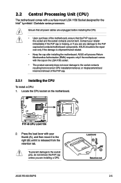
... pins, do not remove the PnP cap unless you see any damage to the PnP cap/socket contacts/motherboard components. ASUS RS100-E6/PI2 Load lever A B Retention tab 2-5 ASUS will process Return Merchandise Authorization (RMA) requests only if the motherboard comes with a surface mount LGA 1156 Socket designed for the Intel® Lynnfield / Clarkdale series processors. Ensure...
... pins, do not remove the PnP cap unless you see any damage to the PnP cap/socket contacts/motherboard components. ASUS RS100-E6/PI2 Load lever A B Retention tab 2-5 ASUS will process Return Merchandise Authorization (RMA) requests only if the motherboard comes with a surface mount LGA 1156 Socket designed for the Intel® Lynnfield / Clarkdale series processors. Ensure...

User Manual
Page 26
Remove the protection sticker on the motherboard. 2-8 Chapter 2: Hardware setup 2.2.2 Installing the CPU heatsink and airduct To install the CPU heatsink: 1. Lift one side of the CPU heatsink. Place the heatsink on top of the installed CPU, ensuring that the four fasteners match the holes on the back of the mylar and set it aside for installing the CPU heatsink. 2. Protection sticker 3.
Remove the protection sticker on the motherboard. 2-8 Chapter 2: Hardware setup 2.2.2 Installing the CPU heatsink and airduct To install the CPU heatsink: 1. Lift one side of the CPU heatsink. Place the heatsink on top of the installed CPU, ensuring that the four fasteners match the holes on the back of the mylar and set it aside for installing the CPU heatsink. 2. Protection sticker 3.
User Manual
Page 27
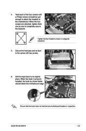
4. Secure the heat pipe and air duct to the server with a Philips (cross) screwdriver just enough to attach the heatsink to the motherboard. Ensure that the mylar does not interfere any motherboard headers or capacitors. A B B A Tighten the four heatsink screws in a diagonal sequence. 5. Set the mylar back to completely secure... each of the four screws with two screws. 6. When the mylar is properly installed, the hook as shown below should attach the motherboard edge. ASUS RS100-E6/PI2 2-9 When the four screws are attached, tighten them one by one to its original place.
4. Secure the heat pipe and air duct to the server with a Philips (cross) screwdriver just enough to attach the heatsink to the motherboard. Ensure that the mylar does not interfere any motherboard headers or capacitors. A B B A Tighten the four heatsink screws in a diagonal sequence. 5. Set the mylar back to completely secure... each of the four screws with two screws. 6. When the mylar is properly installed, the hook as shown below should attach the motherboard edge. ASUS RS100-E6/PI2 2-9 When the four screws are attached, tighten them one by one to its original place.

User Manual
Page 28
... sockets using the memory configurations in this section. For optimum compatibility, it is recommended that you obtain memory modules from the same vendor. • The motherboard supports x8 DRAM only and x4 & x16 DRAM are not supported 2-10 Chapter 2: Hardware setup 2.3 System memory 2.3.1 Overview The...
... sockets using the memory configurations in this section. For optimum compatibility, it is recommended that you obtain memory modules from the same vendor. • The motherboard supports x8 DRAM only and x4 & x16 DRAM are not supported 2-10 Chapter 2: Hardware setup 2.3 System memory 2.3.1 Overview The...
User Manual
Page 29
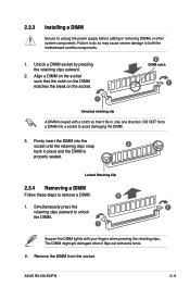
... the motherboard and the components. 1. Remove the DIMM from the socket. Unlock a DIMM socket by pressing the retaining clips outward. 2. Align a DIMM on the socket. 2 DIMM notch 1 1 Unlocked retaining clip A DIMM is properly seated. DO NOT force a DIMM into the socket until the retaining clips snap 3 back in only one direction. ASUS RS100-E6/PI2...
... the motherboard and the components. 1. Remove the DIMM from the socket. Unlock a DIMM socket by pressing the retaining clips outward. 2. Align a DIMM on the socket. 2 DIMM notch 1 1 Unlocked retaining clip A DIMM is properly seated. DO NOT force a DIMM into the socket until the retaining clips snap 3 back in only one direction. ASUS RS100-E6/PI2...
User Manual
Page 33
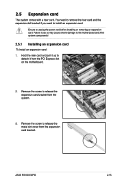
... system comes with a riser card. Ensure to install an expansion card. ASUS RS100-E6/PI2 2-15 Hold the riser card and pull it up to release the expansion card bracket from the PCI Express slot on the motherboard. 2. Remove the screw to the motherboard and other system components! 2.5.1 Installing an expansion card To install an expansion...
... system comes with a riser card. Ensure to install an expansion card. ASUS RS100-E6/PI2 2-15 Hold the riser card and pull it up to release the expansion card bracket from the PCI Express slot on the motherboard. 2. Remove the screw to the motherboard and other system components! 2.5.1 Installing an expansion card To install an expansion...

User Manual
Page 34
Secure the expansion card bracket to the system with the rear panel. 8. 4. Press the riser card until the golden connectors completely fit the slot and the bracket aligns with one screw. 2-16 Chapter 2: Hardware setup Attach the expansion card to the expansion card bracket, and then secure the card with the expansion card installed to the riser card as shown. 5. Align the riser card with a screw. 6. Install the expansion card to the PCI Express slot on the motherboard. 7.
Secure the expansion card bracket to the system with the rear panel. 8. 4. Press the riser card until the golden connectors completely fit the slot and the bracket aligns with one screw. 2-16 Chapter 2: Hardware setup Attach the expansion card to the expansion card bracket, and then secure the card with the expansion card installed to the riser card as shown. 5. Align the riser card with a screw. 6. Install the expansion card to the PCI Express slot on the motherboard. 7.

User Manual
Page 36
... devices. • Refer to Chapter 4 for detailed information on the connectors. 1 3 2 3 3 4 56 Standard cables connected to the motherboard 1. 24-pin ATX power connector (from power supply to motherboard) 2. 8-pin ATX 12V power connector (from motherboard to front I /O board) 2-18 Chapter 2: Hardware setup SATA conectors (system default; 2.6 Cable connections • The bundled system cables...
... devices. • Refer to Chapter 4 for detailed information on the connectors. 1 3 2 3 3 4 56 Standard cables connected to the motherboard 1. 24-pin ATX power connector (from power supply to motherboard) 2. 8-pin ATX 12V power connector (from motherboard to front I /O board) 2-18 Chapter 2: Hardware setup SATA conectors (system default; 2.6 Cable connections • The bundled system cables...
User Manual
Page 37
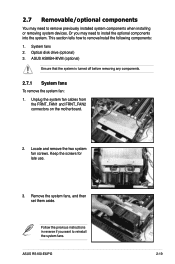
... fans, and then set them aside. Or you want to remove/install the following components: 1. ASUS RS100-E6/PI2 2-19 Optical disk drive (optional) 3. System fans 2. Unplug the system fan cables from the FRNT_FAN1 and FRNT_FAN2 connectors on the motherboard. 2. 2.7 Removable/optional components You may need to install the optional components into the system. Follow...
... fans, and then set them aside. Or you want to remove/install the following components: 1. ASUS RS100-E6/PI2 2-19 Optical disk drive (optional) 3. System fans 2. Unplug the system fan cables from the FRNT_FAN1 and FRNT_FAN2 connectors on the motherboard. 2. 2.7 Removable/optional components You may need to install the optional components into the system. Follow...

User Manual
Page 40
LAN port 3 LAN port 1 2-22 Chapter 2: Hardware setup Locate the BMC_FW1 header on your motherboard. 1. Insert the LAN cable plug to install an optional ASMB4 series management board on the motherboard. 2. 2.7.3 Installing ASMB4 series management board (optional) Follow the steps below to the LAN port 3 (dedicated LAN) or LAN port 1 (shared LAN) for server management. Orient and press the ASMB4 management card in place. 3.
LAN port 3 LAN port 1 2-22 Chapter 2: Hardware setup Locate the BMC_FW1 header on your motherboard. 1. Insert the LAN cable plug to install an optional ASMB4 series management board on the motherboard. 2. 2.7.3 Installing ASMB4 series management board (optional) Follow the steps below to the LAN port 3 (dedicated LAN) or LAN port 1 (shared LAN) for server management. Orient and press the ASMB4 management card in place. 3.

User Manual
Page 47
Motherboard Info Chapter 4 This chapter includes the motherboard layout and brief descriptions of the jumpers and internal connectors.
Motherboard Info Chapter 4 This chapter includes the motherboard layout and brief descriptions of the jumpers and internal connectors.

User Manual
Page 48
4.1 Motherboard layout 4-2 Chapter 4: Motherboard information
4.1 Motherboard layout 4-2 Chapter 4: Motherboard information

User Manual
Page 50
... the CMOS memory of date, time, and system setup parameters by erasing the CMOS RTC RAM data. After the CMOS clearance, reinstall the battery. 4-4 Chapter 4: Motherboard information Hold down the key during the boot process and enter BIOS setup to pins 2-3. Plug the power cord and turn ON the computer. 4. Turn...
... the CMOS memory of date, time, and system setup parameters by erasing the CMOS RTC RAM data. After the CMOS clearance, reinstall the battery. 4-4 Chapter 4: Motherboard information Hold down the key during the boot process and enter BIOS setup to pins 2-3. Plug the power cord and turn ON the computer. 4. Turn...

User Manual
Page 52
... caps over pins 1-2 if you want to use when you create disk arrays. Set to pins 1-2 to use the Intel® Matrix Storage Manager. 4-6 Chapter 4: Motherboard information 4. RAID configuration utility selection (3-pin RAID_SEL1) This jumper allows you to use the LSI Logic Embedded SATA RAID Setup Utility (default); otherwise, place the...
... caps over pins 1-2 if you want to use when you create disk arrays. Set to pins 1-2 to use the Intel® Matrix Storage Manager. 4-6 Chapter 4: Motherboard information 4. RAID configuration utility selection (3-pin RAID_SEL1) This jumper allows you to use the LSI Logic Embedded SATA RAID Setup Utility (default); otherwise, place the...
User Manual
Page 53
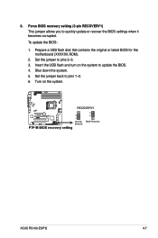
Force BIOS recovery setting (3-pin RECOVERY1) This jumper allows you to pins 2-3. 3. Insert the USB flash and turn on the system. Turn on the system to pins 1-2. 6. Set the jumper to quickly update or recover the BIOS settings when it becomes corrupted. Set the jumper back to update the BIOS. 4. ASUS RS100-E6/PI2 4-7 Prepare a USB flash disk that contains the original or latest BIOS for the motherboard (XXXXXX.ROM). 2. 6. Shut down the system. 5. To update the BIOS: 1.
Force BIOS recovery setting (3-pin RECOVERY1) This jumper allows you to pins 2-3. 3. Insert the USB flash and turn on the system. Turn on the system to pins 1-2. 6. Set the jumper to quickly update or recover the BIOS settings when it becomes corrupted. Set the jumper back to update the BIOS. 4. ASUS RS100-E6/PI2 4-7 Prepare a USB flash disk that contains the original or latest BIOS for the motherboard (XXXXXX.ROM). 2. 6. Shut down the system. 5. To update the BIOS: 1.

User Manual
Page 54
... ATA hard disks installed. 2. Hard disk activity LED connector (4-pin HDLED1) This LED connector is for Serial ATA hard disk drives that allows up . 4-8 Chapter 4: Motherboard information Serial ATA connectors (7-pin SATA1-4 [Red]; 7-pin SATA5-6 [Black]) Supported by the Intel® 3420 chipset, these connectors are for the Serial ATA signal...
... ATA hard disks installed. 2. Hard disk activity LED connector (4-pin HDLED1) This LED connector is for Serial ATA hard disk drives that allows up . 4-8 Chapter 4: Motherboard information Serial ATA connectors (7-pin SATA1-4 [Red]; 7-pin SATA5-6 [Black]) Supported by the Intel® 3420 chipset, these connectors are for the Serial ATA signal...

