
Pundit-PH3/PE3 Quick Start Guide for English Edition
Page 3
...disk drive lock 6. ASUS motherboard 11. If the voltage supply in your area is 100-127 V, set the switch to the voltage supply in your area is 200-240 V, set the switch to 115 V. PCI Express x1 slot 8. PCI slots 9. PCI Express x16 slot (on Pundit-PH3 model only) 10.... Metal bracket lock 12. If the voltage supply in your area. Front panel cover 3. Power supply unit 7. Use this switch to select the appropriate system input voltage according to 230 V. Quick...
...disk drive lock 6. ASUS motherboard 11. If the voltage supply in your area is 100-127 V, set the switch to the voltage supply in your area is 200-240 V, set the switch to 115 V. PCI Express x1 slot 8. PCI slots 9. PCI Express x16 slot (on Pundit-PH3 model only) 10.... Metal bracket lock 12. If the voltage supply in your area. Front panel cover 3. Power supply unit 7. Use this switch to select the appropriate system input voltage according to 230 V. Quick...

Pundit-PH3/PE3 Quick Start Guide for English Edition
Page 7
... of the drive. 2. Insert the card connector to use. 2. Push the drive all the way into the bay until it fits in place. Rubber washer Power cable and plug Signal cable and plug Quick Installation Guide 7 Installing an expansion card 1. Drive two screws with rubber washers on both sides of the... the slot that you intend to the slot, then press the card firmly until the drive lock clicks. 4. Installing a SATA hard disk drive 1. Connect a 4-pin power plug from the power supply unit to the power connector at the back of the drive. 3. Installing an optical drive 1.
... of the drive. 2. Insert the card connector to use. 2. Push the drive all the way into the bay until it fits in place. Rubber washer Power cable and plug Signal cable and plug Quick Installation Guide 7 Installing an expansion card 1. Drive two screws with rubber washers on both sides of the... the slot that you intend to the slot, then press the card firmly until the drive lock clicks. 4. Installing a SATA hard disk drive 1. Connect a 4-pin power plug from the power supply unit to the power connector at the back of the drive. 3. Installing an optical drive 1.

Pundit-PE3 User''s Manusl for English
Page 7
... empfohlenem ähnljchen Typ. Operation safety • Before installing devices into the system, carefully read all the documentation that the power cables for the devices are unplugged before relocating the system. • When adding or removing devices to or from the system,...that came with the package. • Before using the product, make sure all cables are correctly connected and the power cables are connected. • If the power supply is incorrectly replaced. LASER PRODUCT WARNING CLASS 1 LASER PRODUCT vii Contact a qualified service technician or your dealer immediately....
... empfohlenem ähnljchen Typ. Operation safety • Before installing devices into the system, carefully read all the documentation that the power cables for the devices are unplugged before relocating the system. • When adding or removing devices to or from the system,...that came with the package. • Before using the product, make sure all cables are correctly connected and the power cables are connected. • If the power supply is incorrectly replaced. LASER PRODUCT WARNING CLASS 1 LASER PRODUCT vii Contact a qualified service technician or your dealer immediately....
Pundit-PE3 User''s Manusl for English
Page 10
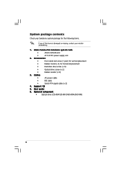
... items. If any of the items is damaged or missing, contact your retailer immediately. 1. Cables • AC power cable • IDE cable • Serial ATA signal cable (x 2) 4. Optional component • Optical drive (CD-ROM/CD-RW/DVD-ROM/DVD-RW) x Support CD 5. ASUS Pundit-PE3 barebone system with • ASUS motherboard • 275 W PFC power supply unit 2.
... items. If any of the items is damaged or missing, contact your retailer immediately. 1. Cables • AC power cable • IDE cable • Serial ATA signal cable (x 2) 4. Optional component • Optical drive (CD-ROM/CD-RW/DVD-ROM/DVD-RW) x Support CD 5. ASUS Pundit-PE3 barebone system with • ASUS motherboard • 275 W PFC power supply unit 2.

Pundit-PE3 User''s Manusl for English
Page 14
... and plug. 1 1 . This port allows Fast Ethernet connection to the voltage supply in your area. Secures the expansion slot/card metal brackets. 9 . P S / 2 k e y b o a r d p o r t . V G A p o r t . PS/2 mouse port . L A N ( R J - 4 5 ) p o r t . V o l t a g e s e l e c t o r . P o w e r c o n n e c t o r . Connects the power plug is for the system. 5 . 6 - 1.3 Rear panel The system rear panel includes the power connector and several I E E E 1 3 9 4 a p o r t . Secures the system cover. 2 . This green 6-pin connector...
... and plug. 1 1 . This port allows Fast Ethernet connection to the voltage supply in your area. Secures the expansion slot/card metal brackets. 9 . P S / 2 k e y b o a r d p o r t . V G A p o r t . PS/2 mouse port . L A N ( R J - 4 5 ) p o r t . V o l t a g e s e l e c t o r . P o w e r c o n n e c t o r . Connects the power plug is for the system. 5 . 6 - 1.3 Rear panel The system rear panel includes the power connector and several I E E E 1 3 9 4 a p o r t . Secures the system cover. 2 . This green 6-pin connector...

Pundit-PE3 User''s Manusl for English
Page 15
... table below for the power supply unit. U S B 2 . 0 p o r t s . In 4/6-channel mode, the function of this port becomes Front Speaker Out. 1 6 . M i c r o p h o n e p o r t . In 4/6-channel mode, the function of this port becomes Surround Speaker. The functions of the Line Out, Line In, and Microphone ports change when you select the 6-channel configuration. ASUS Pundit-PE3 1-5 1 4 . Covers the PCI Express...
... table below for the power supply unit. U S B 2 . 0 p o r t s . In 4/6-channel mode, the function of this port becomes Front Speaker Out. 1 6 . M i c r o p h o n e p o r t . In 4/6-channel mode, the function of this port becomes Surround Speaker. The functions of the Line Out, Line In, and Microphone ports change when you select the 6-channel configuration. ASUS Pundit-PE3 1-5 1 4 . Covers the PCI Express...

Pundit-PE3 User''s Manusl for English
Page 16
... illustration below is the internal view of the system when you remove the top cover and the chassis support bracket. Power supply unit 7. DIMM sockets 1-6 Chapter 1: System introduction Hard disk drive lock 6. ASUS motherboard 10. PCI slots 9. The installed components are labeled for instructions on installing additional system components. 12 11 9 8 10 7 6 1 13...
... illustration below is the internal view of the system when you remove the top cover and the chassis support bracket. Power supply unit 7. DIMM sockets 1-6 Chapter 1: System introduction Hard disk drive lock 6. ASUS motherboard 10. PCI slots 9. The installed components are labeled for instructions on installing additional system components. 12 11 9 8 10 7 6 1 13...

Pundit-PE3 User''s Manusl for English
Page 18
...; Whenever you install components into the system. • Use a grounded wrist strap or touch a safely grounded object or a metal object, such as the power supply case, before installing any component, place it on a grounded antistatic pad or in the bag that came with an onboard standby... power LED. Central processing unit (CPU) 2. Unplug the power cable from the power outlet and make sure that the system is OFF before handling components to avoid damaging them due to static electricity...
...; Whenever you install components into the system. • Use a grounded wrist strap or touch a safely grounded object or a metal object, such as the power supply case, before installing any component, place it on a grounded antistatic pad or in the bag that came with an onboard standby... power LED. Central processing unit (CPU) 2. Unplug the power cable from the power outlet and make sure that the system is OFF before handling components to avoid damaging them due to static electricity...

Pundit-PE3 User''s Manusl for English
Page 27
...flips out with your fingers when pressing the retaining clips. Locked retaining clip 2.5.3 Removing a DIMM Follow these steps to unplug the power supply before adding or removing DIMMs or other system components. Firmly insert the DIMM into a socket to unlock the DIMM. Support the... sure to install a DIMM. 1. Remove the DIMM from the socket. DDR DIMM notch Unlocked retaining clip A DDR DIMM is properly seated. ASUS Pundit-PE3 2-11 Follow these steps to both the motherboard and the components. Align a DIMM on the socket. DO NOT force a DIMM into the socket...
...flips out with your fingers when pressing the retaining clips. Locked retaining clip 2.5.3 Removing a DIMM Follow these steps to unplug the power supply before adding or removing DIMMs or other system components. Firmly insert the DIMM into a socket to unlock the DIMM. Support the... sure to install a DIMM. 1. Remove the DIMM from the socket. DDR DIMM notch Unlocked retaining clip A DDR DIMM is properly seated. ASUS Pundit-PE3 2-11 Follow these steps to both the motherboard and the components. Align a DIMM on the socket. DO NOT force a DIMM into the socket...

Pundit-PE3 User''s Manusl for English
Page 32
Connect a 4-pin power plug from the power supply unit to release the optical drive screw (A), then slightly pull the drive out from the bay (B). Locate the optical drive screw lock. 3. Push the lock to the power connector at the back of the drive. 5. To uninstall the optical drive: 1. B A 4. Uninstalling the ... push the optical drive all the way into the bay until the optical drive lock clicks. 8. Disconnect the IDE, audio, and power cables and plugs from the bay, then replace it following the instructions in the previous section. 2-16 Chapter 2: Basic installation 7.
Connect a 4-pin power plug from the power supply unit to release the optical drive screw (A), then slightly pull the drive out from the bay (B). Locate the optical drive screw lock. 3. Push the lock to the power connector at the back of the drive. 5. To uninstall the optical drive: 1. B A 4. Uninstalling the ... push the optical drive all the way into the bay until the optical drive lock clicks. 8. Disconnect the IDE, audio, and power cables and plugs from the bay, then replace it following the instructions in the previous section. 2-16 Chapter 2: Basic installation 7.

Pundit-PE3 User''s Manusl for English
Page 34
... properly in place. HDD screw lock 2-18 Chapter 2: Basic installation Connect one end of the supplied 7-pin SATA cable to a SATA connector on the motherboard. Connect the 15-pin SATA power plug from the power supply unit to the power connector at the back of the drive, then connect the other end to the SATA...
... properly in place. HDD screw lock 2-18 Chapter 2: Basic installation Connect one end of the supplied 7-pin SATA cable to a SATA connector on the motherboard. Connect the 15-pin SATA power plug from the power supply unit to the power connector at the back of the drive, then connect the other end to the SATA...
Pundit-PE3 User''s Manusl for English
Page 35
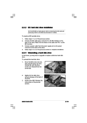
... future, you may have to the IDE interface at the back of the drive. 4. Install a new HDD following the instructions in the previous section. ASUS Pundit-PE3 2-19 To install an IDE hard disk drive: 1. Connect the IDE cable (gray connector) to upgrade or replace a defective hard disk drive. B... before connecting the IDE cable and power plug. Follow steps 1 to the HDD documentation for details. Press the HDD screw lock (A), then push the drive out from the bay (B) until the drive screws are released from the power supply unit to the power connector at the back of the ...
... future, you may have to the IDE interface at the back of the drive. 4. Install a new HDD following the instructions in the previous section. ASUS Pundit-PE3 2-19 To install an IDE hard disk drive: 1. Connect the IDE cable (gray connector) to upgrade or replace a defective hard disk drive. B... before connecting the IDE cable and power plug. Follow steps 1 to the HDD documentation for details. Press the HDD screw lock (A), then push the drive out from the bay (B) until the drive screws are released from the power supply unit to the power connector at the back of the ...

Pundit-PE3 User''s Manusl for English
Page 39
... devices To the front panel Camera Headphone or Audio Device Scanner Mic ASUS Pundit-PE3 2-23 2.11 Selecting the voltage The system's power supply unit has a 115 V/230 V voltage selector switch located beside the power connector. Setting the switch to 115 V. If the voltage supply in your area is 100-127 V, set the switch to the voltage...
... devices To the front panel Camera Headphone or Audio Device Scanner Mic ASUS Pundit-PE3 2-23 2.11 Selecting the voltage The system's power supply unit has a 115 V/230 V voltage selector switch located beside the power connector. Setting the switch to 115 V. If the voltage supply in your area is 100-127 V, set the switch to the voltage...

Pundit-PE3 User''s Manusl for English
Page 52
...Chapter 4: Motherboard info USB device wake-up (3-pin USBPW12, USBPW34, USBPW56, USBPW78) Set these jumpers to +5V to CPU, DRAM in slow refresh, power supply in low power mode) using the connected USB devices. USBPW12 USBPW34 2 1 +5V (Default) 3 2 +5VSB USBPW56 ® USBPW78 12 23 USB device wake-...8226; The total current consumed must NOT exceed the power supply capability (+5VSB) whether under normal condition or in the BIOS. otherwise, the system will not power up feature. This feature requires an ATX power supply that can supply at least 1A on the +5VSB lead for each...
...Chapter 4: Motherboard info USB device wake-up (3-pin USBPW12, USBPW34, USBPW56, USBPW78) Set these jumpers to +5V to CPU, DRAM in slow refresh, power supply in low power mode) using the connected USB devices. USBPW12 USBPW34 2 1 +5V (Default) 3 2 +5VSB USBPW56 ® USBPW78 12 23 USB device wake-...8226; The total current consumed must NOT exceed the power supply capability (+5VSB) whether under normal condition or in the BIOS. otherwise, the system will not power up feature. This feature requires an ATX power supply that can supply at least 1A on the +5VSB lead for each...

Pundit-PE3 User''s Manusl for English
Page 56
... out_L 4-8 Chapter 4: Motherboard info The plugs from the power supply are for ATX power supply plugs. ATX power connectors (24-pin EATXPWR1, 4-pin ATX12V1) These connectors are pre-connected to connect the 4-pin ATX +12 V power plug; 6. Front panel audio connector (10-1 pin AAFP1... Ground -12 Volts +3 Volts Important notes on the motherboard power requirements • Do not forget to these connectors. otherwise, the system will not boot up. • The system comes with a proprietary ATX 12 V Specification 2.0 power supply unit (PSU) with the legacy AC'97 audio standard.
... out_L 4-8 Chapter 4: Motherboard info The plugs from the power supply are for ATX power supply plugs. ATX power connectors (24-pin EATXPWR1, 4-pin ATX12V1) These connectors are pre-connected to connect the 4-pin ATX +12 V power plug; 6. Front panel audio connector (10-1 pin AAFP1... Ground -12 Volts +3 Volts Important notes on the motherboard power requirements • Do not forget to these connectors. otherwise, the system will not boot up. • The system comes with a proprietary ATX 12 V Specification 2.0 power supply unit (PSU) with the legacy AC'97 audio standard.

Pundit-PE3 User''s Manusl for English
Page 58
... Requires an ATX power supply. The sytem panel connector is color-coded for the system power button. The IDE LED lights up or flashes when data is read from or written to the HDD. • ATX power button/soft-off mode depending on the BIOS settings. Pressing the power switch for the... connector IDE_LED+ IDE_LED- System panel connector (10-1 pin F_PANEL1) This connector supports several chassis-mounted functions. Refer to this connector. Pressing the power button turns the system on or puts the system in sleep or soft-off button (Yellow 2-pin PWRSW) This connector is ON turns the ...
... Requires an ATX power supply. The sytem panel connector is color-coded for the system power button. The IDE LED lights up or flashes when data is read from or written to the HDD. • ATX power button/soft-off mode depending on the BIOS settings. Pressing the power switch for the... connector IDE_LED+ IDE_LED- System panel connector (10-1 pin F_PANEL1) This connector supports several chassis-mounted functions. Refer to this connector. Pressing the power button turns the system on or puts the system in sleep or soft-off button (Yellow 2-pin PWRSW) This connector is ON turns the ...

Pundit-PE3 User''s Manusl for English
Page 80
... or change the keyboard wakeup password. The K e y b o a r d W a k e u p P a s s w o r d item that turns the system power on the system. This feature requires an ATX power supply that provides at least 1A on the +5VSB lead. Select this item shows I n s t a l l e d. This feature requires an ATX power supply that provides at least 1A on the +5VSB lead. Configuration options: [Disabled...
... or change the keyboard wakeup password. The K e y b o a r d W a k e u p P a s s w o r d item that turns the system power on the system. This feature requires an ATX power supply that provides at least 1A on the +5VSB lead. Select this item shows I n s t a l l e d. This feature requires an ATX power supply that provides at least 1A on the +5VSB lead. Configuration options: [Disabled...


