User Manual
Page 10
...Speaker connector 1 x Chassis intrusion connector 1 x 24-pin EATX power connector 1 x 4-pin ATX 12V power connector 1 x System panel connector 1 x TPM IC onboard (P8H67-M2/TPM/SI only) 32 Mb Flash ROM, EFI AMI BIOS, PnP, DMI 2.0, WfM 2.0, ACPI 2.0a, SM BIOS 2.6, Multi-language BIOS 2 x Serial ATA 3.0Gb/s cables 1... x I/O shield 1 x User Manual 1 x Support DVD Drivers ASUS utilities ASUS Update Anti-virus software (OEM version) MicroATX form factor: 9.6 in x ...
...Speaker connector 1 x Chassis intrusion connector 1 x 24-pin EATX power connector 1 x 4-pin ATX 12V power connector 1 x System panel connector 1 x TPM IC onboard (P8H67-M2/TPM/SI only) 32 Mb Flash ROM, EFI AMI BIOS, PnP, DMI 2.0, WfM 2.0, ACPI 2.0a, SM BIOS 2.6, Multi-language BIOS 2 x Serial ATA 3.0Gb/s cables 1... x I/O shield 1 x User Manual 1 x Support DVD Drivers ASUS utilities ASUS Update Anti-virus software (OEM version) MicroATX form factor: 9.6 in x ...
User Manual
Page 11
...this user guide are for buying an ASUS® P8H67-M2 Series motherboard! SB_PWR P8H67-M2/TPM/SI ON OFF Standby Power Powered Off P8H67-M2/TPM/SI Onboard LED Chapter 1: Product introduction 1-1 The layout illustrations in the bag that came with models. ASUS P8H67-M2 Series motherboards include P8H67-M2/SI and P8H67-M2/TPM/SI two models. Chapter 1 Product introduction ... your retailer. Before you uninstall any of the onboard LED. The layout varies with the component. • Before you for P8H67-M2/TPM/SI only. 1.1 Before you proceed Take note of accessories.
...this user guide are for buying an ASUS® P8H67-M2 Series motherboard! SB_PWR P8H67-M2/TPM/SI ON OFF Standby Power Powered Off P8H67-M2/TPM/SI Onboard LED Chapter 1: Product introduction 1-1 The layout illustrations in the bag that came with models. ASUS P8H67-M2 Series motherboards include P8H67-M2/SI and P8H67-M2/TPM/SI two models. Chapter 1 Product introduction ... your retailer. Before you uninstall any of the onboard LED. The layout varies with the component. • Before you for P8H67-M2/TPM/SI only. 1.1 Before you proceed Take note of accessories.
User Manual
Page 12
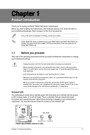
Doing so can damage the motherboard. 1-2 ASUS P8H67-M2 Series DO NOT overtighten the screws! 1.2 1.2.1 Motherboard overview Motherboard layout Ensure that you install the motherboard into the holes indicated by circles to secure ...module) DDR3 DIMM_B2 (64bit, 240-pin module) VGA LGA1155 24.4cm(9.6in) USB34 EATXPWR LAN1_USB12 Lithium Cell CHA_FAN CMOS Power 2 AUDIO PCIEX16 RTL 8111E P8H67-M2/TPM/SI PCI1 7 SB_PWR 8 TPM IC asmedia ASM1083 PCI2 VIA VT1708S SPDIF_OUT PCIEX1_1 AAFP USB1314 USB1112 USB910 Intel® H67 CHASSIS CLRTC 32Mb BIOS SATA3G_3 SATA3G_1 ...
Doing so can damage the motherboard. 1-2 ASUS P8H67-M2 Series DO NOT overtighten the screws! 1.2 1.2.1 Motherboard overview Motherboard layout Ensure that you install the motherboard into the holes indicated by circles to secure ...module) DDR3 DIMM_B2 (64bit, 240-pin module) VGA LGA1155 24.4cm(9.6in) USB34 EATXPWR LAN1_USB12 Lithium Cell CHA_FAN CMOS Power 2 AUDIO PCIEX16 RTL 8111E P8H67-M2/TPM/SI PCI1 7 SB_PWR 8 TPM IC asmedia ASM1083 PCI2 VIA VT1708S SPDIF_OUT PCIEX1_1 AAFP USB1314 USB1112 USB910 Intel® H67 CHASSIS CLRTC 32Mb BIOS SATA3G_3 SATA3G_1 ...
User Manual
Page 14
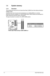
... four Double Data Rate 3 (DDR3) Dual Inline Memory Modules (DIMM) sockets. The figure illustrates the location of the DDR3 DIMM sockets: DIMM_A1 DIMM_A2 DIMM_B1 DIMM_B2 P8H67-M2/TPM/SI Channel Channel A Channel B Sockets DIMM_A1 and DIMM_A2 DIMM_B1 and DIMM_B2 P8H67-M2/TPM/SI 240-pin DDR3 DIMM sockets 1-4 ASUS P8H67-M2 Series
... four Double Data Rate 3 (DDR3) Dual Inline Memory Modules (DIMM) sockets. The figure illustrates the location of the DDR3 DIMM sockets: DIMM_A1 DIMM_A2 DIMM_B1 DIMM_B2 P8H67-M2/TPM/SI Channel Channel A Channel B Sockets DIMM_A1 and DIMM_A2 DIMM_B1 and DIMM_B2 P8H67-M2/TPM/SI 240-pin DDR3 DIMM sockets 1-4 ASUS P8H67-M2 Series
User Manual
Page 18
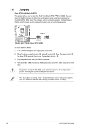
... to clear the CMOS RTC RAM data. After clearing the CMOS, reinstall the battery. 1-8 ASUS P8H67-M2 Series The onboard button cell battery powers the RAM data in CMOS. P8H67-M2/TPM/SI CLRTC 12 23 Normal (Default) Clear RTC P8H67-M2/TPM/SI Clear RTC RAM To erase the RTC RAM: 1. You can clear the CMOS memory of...
... to clear the CMOS RTC RAM data. After clearing the CMOS, reinstall the battery. 1-8 ASUS P8H67-M2 Series The onboard button cell battery powers the RAM data in CMOS. P8H67-M2/TPM/SI CLRTC 12 23 Normal (Default) Clear RTC P8H67-M2/TPM/SI Clear RTC RAM To erase the RTC RAM: 1. You can clear the CMOS memory of...
User Manual
Page 20
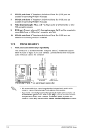
...to [HD]. These two 4-pin Universal Serial Bus (USB) ports are available for connecting USB 2.0/1.1 devices. 7. This port is for details. 1-10 ASUS P8H67-M2 Series USB 2.0 ports 5 and 6. These two 4-pin Universal Serial Bus (USB) ports are available for a chassis-mounted front panel audio I . ...1 MIC2 MICPWR Line out_R NC Line out_L PORT1 L PORT1 R PORT2 R SENSE_SEND PORT2 L P8H67-M2/TPM/SI HD-audio-compliant Legacy AC'97 pin definition compliant definition P8H67-M2/TPM/SI Front panel audio connector • We recommend that supports either HD Audio or legacy AC`97 ...
...to [HD]. These two 4-pin Universal Serial Bus (USB) ports are available for connecting USB 2.0/1.1 devices. 7. This port is for details. 1-10 ASUS P8H67-M2 Series USB 2.0 ports 5 and 6. These two 4-pin Universal Serial Bus (USB) ports are available for a chassis-mounted front panel audio I . ...1 MIC2 MICPWR Line out_R NC Line out_L PORT1 L PORT1 R PORT2 R SENSE_SEND PORT2 L P8H67-M2/TPM/SI HD-audio-compliant Legacy AC'97 pin definition compliant definition P8H67-M2/TPM/SI Front panel audio connector • We recommend that supports either HD Audio or legacy AC`97 ...
User Manual
Page 22
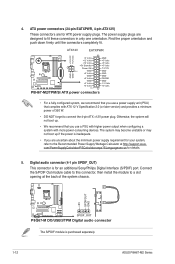
...an additional Sony/Philips Digital Interface (S/PDIF) port. 4. Digital audio connector (4-1 pin SPDIF_OUT) This connector is purchased separately. 1-12 ASUS P8H67-M2 Series Connect the S/PDIF Out module cable to this connector, then install the module to connect the 4-pin ATX +12V power plug...Volts GND +3 Volts +3 Volts PIN 1 GND +5 Volts +5 Volts +5 Volts -5 Volts GND GND GND PSON# GND -12 Volts +3 Volts P8H67-M2/TPM/SI ATX power connectors • For a fully configured system, we recommend that complies with more power-consuming devices. The system may become unstable or may...
...an additional Sony/Philips Digital Interface (S/PDIF) port. 4. Digital audio connector (4-1 pin SPDIF_OUT) This connector is purchased separately. 1-12 ASUS P8H67-M2 Series Connect the S/PDIF Out module cable to this connector, then install the module to connect the 4-pin ATX +12V power plug...Volts GND +3 Volts +3 Volts PIN 1 GND +5 Volts +5 Volts +5 Volts -5 Volts GND GND GND PSON# GND -12 Volts +3 Volts P8H67-M2/TPM/SI ATX power connectors • For a fully configured system, we recommend that complies with more power-consuming devices. The system may become unstable or may...
User Manual
Page 24
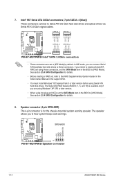
...3 or later version before using Serial ATA hard disk drives. SPEAKER +5V GND GND Speaker Out P8H67-M2/TPM/SI PIN 1 P8H67-M2/TPM/SI Speaker connector 1-14 ASUS P8H67-M2 Series Speaker connector (4-pin SPEAKER) The 4-pin connector is available only if you can connect Serial ATA... RSATA_TXN3 GND RSATA_RXP3 RSATA_RXN3 GND GND RSATA_RXN2 RSATA_RXP2 GND RSATA_TXN2 RSATA_TXP2 GND GND RSATA_RXN4 RSATA_RXP4 GND RSATA_TXN4 RSATA_TXP4 GND P8H67-M2/TPM/SI SATA3G_4 SATA3G_2 P8H67-M2/TPM/SI Intel® SATA 3.0Gb/s connectors • These connectors are using Windows® XP SP3 or later ...
...3 or later version before using Serial ATA hard disk drives. SPEAKER +5V GND GND Speaker Out P8H67-M2/TPM/SI PIN 1 P8H67-M2/TPM/SI Speaker connector 1-14 ASUS P8H67-M2 Series Speaker connector (4-pin SPEAKER) The 4-pin connector is available only if you can connect Serial ATA... RSATA_TXN3 GND RSATA_RXP3 RSATA_RXN3 GND GND RSATA_RXN2 RSATA_RXP2 GND RSATA_TXN2 RSATA_TXP2 GND GND RSATA_RXN4 RSATA_RXP4 GND RSATA_TXN4 RSATA_TXP4 GND P8H67-M2/TPM/SI SATA3G_4 SATA3G_2 P8H67-M2/TPM/SI Intel® SATA 3.0Gb/s connectors • These connectors are using Windows® XP SP3 or later ...
User Manual
Page 26
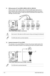
... port connector (10-1 pin COM1) This connector is for USB 2.0 ports. Doing so will damage the motherboard! COM1 PIN 1 P8H67-M2/TPM/SI P8H67-M2/TPM/SI Serial port (COM1) connector The COM module is purchased separately. 12. Connect the USB module cable to any of these connectors, then...port. These USB connectors comply with USB 2.0 specification that supports up to the USB connectors. The USB module cable is purchased separately. 1-16 ASUS P8H67-M2 Series 11. Connect the serial port module cable to this connector, then install the module to a slot opening at the back of the ...
... port connector (10-1 pin COM1) This connector is for USB 2.0 ports. Doing so will damage the motherboard! COM1 PIN 1 P8H67-M2/TPM/SI P8H67-M2/TPM/SI Serial port (COM1) connector The COM module is purchased separately. 12. Connect the USB module cable to any of these connectors, then...port. These USB connectors comply with USB 2.0 specification that supports up to the USB connectors. The USB module cable is purchased separately. 1-16 ASUS P8H67-M2 Series 11. Connect the serial port module cable to this connector, then install the module to a slot opening at the back of the ...

User Manual
Page 30
...updating itself through the Internet. Go to the Tool menu to select ASUS EZ Flash Utility and press to update the BIOS without using EZ Flash 2: 1. ASUSTek EZ Flash BIOS ROM Utility V00.75 Flash Info MODEL: P8H67-M2/TPM/SI File Path: fs0:\ Drive fs0:\ VER: 0201 Folder Info 03/21.../2011 10:23p 8388608 Exit DATE: 03/21/2011 P8H67M2T.ROM File Info MODEL: Help Info VER: DATE [Enter] Select or Load [Tab] Switch [Up/Down/PageUp/PageDown/Home/End] Move [Esc] Exit [F2] Backup 2-2 ASUS P8H67-M2 Series...
...updating itself through the Internet. Go to the Tool menu to select ASUS EZ Flash Utility and press to update the BIOS without using EZ Flash 2: 1. ASUSTek EZ Flash BIOS ROM Utility V00.75 Flash Info MODEL: P8H67-M2/TPM/SI File Path: fs0:\ Drive fs0:\ VER: 0201 Folder Info 03/21.../2011 10:23p 8388608 Exit DATE: 03/21/2011 P8H67M2T.ROM File Info MODEL: Help Info VER: DATE [Enter] Select or Load [Tab] Switch [Up/Down/PageUp/PageDown/Home/End] Move [Esc] Exit [F2] Backup 2-2 ASUS P8H67-M2 Series...
User Manual
Page 31
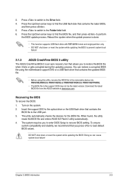
...corrupted during the updating process. Chapter 2: BIOS information 2-3 The utility automatically checks the devices for P8H67-M2/TPM/SI). • The BIOS file in the removable device into P8H67M2.ROM (for P8H67-M2/SI) or P8H67M2T.ROM (for the BIOS file. You can cause system boot failure! DO NOT ...shut down or reset the system while updating the BIOS to prevent system boot failure! 2.1.3 ASUS CrashFree BIOS 3 utility The ASUS CrashFree BIOS 3 is an auto...
...corrupted during the updating process. Chapter 2: BIOS information 2-3 The utility automatically checks the devices for P8H67-M2/TPM/SI). • The BIOS file in the removable device into P8H67M2.ROM (for P8H67-M2/SI) or P8H67M2T.ROM (for the BIOS file. You can cause system boot failure! DO NOT ...shut down or reset the system while updating the BIOS to prevent system boot failure! 2.1.3 ASUS CrashFree BIOS 3 utility The ASUS CrashFree BIOS 3 is an auto...

User Manual
Page 34
... Updater screen appears as below. BIOS Updater checks the selected BIOS file and prompts you have disconnected them. 2-6 ASUS P8H67-M2 Series Refer to section 2.9 Exit menu for DOS V1.18 Current ROM BOARD: P8H67-M2/TPM/SI VER: 0201 DATE: 03/21/2011 Update ROM BOARD: Unknown VER: Unknown DATE: Unknown PATH: A:\ A: P8H67M2T.ROM 8388608...
... Updater screen appears as below. BIOS Updater checks the selected BIOS file and prompts you have disconnected them. 2-6 ASUS P8H67-M2 Series Refer to section 2.9 Exit menu for DOS V1.18 Current ROM BOARD: P8H67-M2/TPM/SI VER: 0201 DATE: 03/21/2011 Update ROM BOARD: Unknown VER: Unknown DATE: Unknown PATH: A:\ A: P8H67M2T.ROM 8388608...
User Manual
Page 36
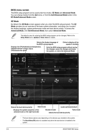
...installed to the system. • The Boot Menu(F8) button is available only when the boot device is installed to the system. 2-8 ASUS P8H67-M2 Series Boot Menu(F8) Default(F5) Selects the boot device priority Silent mode Loads optimized default Displays the system properties of the BIOS setup ... EZ Mode provides you an overview of the basic system information, and allows you enter the BIOS setup program. EZ Mode Friday [10/08/2010] P8H67-M2/TPM/SI BIOS Version : 0201 CPU Type : Intel(R) Core(TM) i5-2400 CPU @ 3.10GHz Total Memory : 1024 MB (DDR3 1333MHz) Build Date :...
...installed to the system. • The Boot Menu(F8) button is available only when the boot device is installed to the system. 2-8 ASUS P8H67-M2 Series Boot Menu(F8) Default(F5) Selects the boot device priority Silent mode Loads optimized default Displays the system properties of the BIOS setup ... EZ Mode provides you an overview of the basic system information, and allows you enter the BIOS setup program. EZ Mode Friday [10/08/2010] P8H67-M2/TPM/SI BIOS Version : 0201 CPU Type : Intel(R) Core(TM) i5-2400 CPU @ 3.10GHz Total Memory : 1024 MB (DDR3 1333MHz) Build Date :...
User Manual
Page 56
... following two conditions: (1) This device may cause undesired operation. Operation is subject to the following apparatus: Product name : Motherboard Model name : P8H67-M2/SI, P8H67-M2/TPM/SI conform with part 15 of the FCC Rules. DECLARATION OF CONFORMITY Per FCC Part 2 Section 2. 1077(a) Responsible Party Name: Asus Computer International Address: 800 Corporate Way, Fremont, CA 94539.
... following two conditions: (1) This device may cause undesired operation. Operation is subject to the following apparatus: Product name : Motherboard Model name : P8H67-M2/SI, P8H67-M2/TPM/SI conform with part 15 of the FCC Rules. DECLARATION OF CONFORMITY Per FCC Part 2 Section 2. 1077(a) Responsible Party Name: Asus Computer International Address: 800 Corporate Way, Fremont, CA 94539.


