User Manual
Page 1
Motherboard P8H67-M2/SI P8H67-M2/TPM/SI
Motherboard P8H67-M2/SI P8H67-M2/TPM/SI
User Manual
Page 10
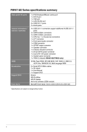
...1 x Speaker connector 1 x Chassis intrusion connector 1 x 24-pin EATX power connector 1 x 4-pin ATX 12V power connector 1 x System panel connector 1 x TPM IC onboard (P8H67-M2/TPM/SI only) 32 Mb Flash ROM, EFI AMI BIOS, PnP, DMI 2.0, WfM 2.0, ACPI 2.0a, SM BIOS 2.6, Multi-language BIOS 2 x Serial ATA 3.0Gb/s... cables 1 x I/O shield 1 x User Manual 1 x Support DVD Drivers ASUS utilities ASUS Update Anti-virus software (OEM version) MicroATX form ...
...1 x Speaker connector 1 x Chassis intrusion connector 1 x 24-pin EATX power connector 1 x 4-pin ATX 12V power connector 1 x System panel connector 1 x TPM IC onboard (P8H67-M2/TPM/SI only) 32 Mb Flash ROM, EFI AMI BIOS, PnP, DMI 2.0, WfM 2.0, ACPI 2.0a, SM BIOS 2.6, Multi-language BIOS 2 x Serial ATA 3.0Gb/s... cables 1 x I/O shield 1 x User Manual 1 x Support DVD Drivers ASUS utilities ASUS Update Anti-virus software (OEM version) MicroATX form ...
User Manual
Page 11
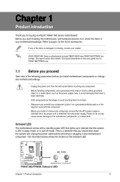
...cord is detached from the wall socket before removing or plugging in the bag that came with models. ASUS P8H67-M2 Series motherboards include P8H67-M2/SI and P8H67-M2/TPM/SI two models. Chapter 1 Product introduction Thank you start installing the motherboard, and hardware devices on it ...grounded antistatic pad or in any of the onboard LED. SB_PWR P8H67-M2/TPM/SI ON OFF Standby Power Powered Off P8H67-M2/TPM/SI Onboard LED Chapter 1: Product introduction 1-1 Refer to page x for buying an ASUS® P8H67-M2 Series motherboard! The layout varies with the component. •...
...cord is detached from the wall socket before removing or plugging in the bag that came with models. ASUS P8H67-M2 Series motherboards include P8H67-M2/SI and P8H67-M2/TPM/SI two models. Chapter 1 Product introduction Thank you start installing the motherboard, and hardware devices on it ...grounded antistatic pad or in any of the onboard LED. SB_PWR P8H67-M2/TPM/SI ON OFF Standby Power Powered Off P8H67-M2/TPM/SI Onboard LED Chapter 1: Product introduction 1-1 Refer to page x for buying an ASUS® P8H67-M2 Series motherboard! The layout varies with the component. •...
User Manual
Page 12
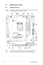
The edge with external ports goes to the chassis. Doing so can damage the motherboard. 1-2 ASUS P8H67-M2 Series 1.2 1.2.1 Motherboard overview Motherboard layout Ensure that you install the motherboard into the holes indicated by circles to secure ...64bit, 240-pin module) VGA LGA1155 24.4cm(9.6in) USB34 EATXPWR LAN1_USB12 Lithium Cell CHA_FAN CMOS Power 2 AUDIO PCIEX16 RTL 8111E P8H67-M2/TPM/SI PCI1 7 SB_PWR 8 TPM IC asmedia ASM1083 PCI2 VIA VT1708S SPDIF_OUT PCIEX1_1 AAFP USB1314 USB1112 USB910 Intel® H67 CHASSIS CLRTC 32Mb BIOS SATA3G_3 SATA3G_1 SATA6G_1 ...
The edge with external ports goes to the chassis. Doing so can damage the motherboard. 1-2 ASUS P8H67-M2 Series 1.2 1.2.1 Motherboard overview Motherboard layout Ensure that you install the motherboard into the holes indicated by circles to secure ...64bit, 240-pin module) VGA LGA1155 24.4cm(9.6in) USB34 EATXPWR LAN1_USB12 Lithium Cell CHA_FAN CMOS Power 2 AUDIO PCIEX16 RTL 8111E P8H67-M2/TPM/SI PCI1 7 SB_PWR 8 TPM IC asmedia ASM1083 PCI2 VIA VT1708S SPDIF_OUT PCIEX1_1 AAFP USB1314 USB1112 USB910 Intel® H67 CHASSIS CLRTC 32Mb BIOS SATA3G_3 SATA3G_1 SATA6G_1 ...
User Manual
Page 14
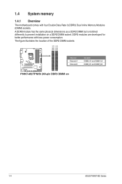
... Double Data Rate 3 (DDR3) Dual Inline Memory Modules (DIMM) sockets. The figure illustrates the location of the DDR3 DIMM sockets: DIMM_A1 DIMM_A2 DIMM_B1 DIMM_B2 P8H67-M2/TPM/SI Channel Channel A Channel B Sockets DIMM_A1 and DIMM_A2 DIMM_B1 and DIMM_B2 P8H67-M2/TPM/SI 240-pin DDR3 DIMM sockets 1-4 ASUS P8H67-M2 Series 1.4 System memory 1.4.1 Overview The motherboard comes with less power consumption.
... Double Data Rate 3 (DDR3) Dual Inline Memory Modules (DIMM) sockets. The figure illustrates the location of the DDR3 DIMM sockets: DIMM_A1 DIMM_A2 DIMM_B1 DIMM_B2 P8H67-M2/TPM/SI Channel Channel A Channel B Sockets DIMM_A1 and DIMM_A2 DIMM_B1 and DIMM_B2 P8H67-M2/TPM/SI 240-pin DDR3 DIMM sockets 1-4 ASUS P8H67-M2 Series 1.4 System memory 1.4.1 Overview The motherboard comes with less power consumption.
User Manual
Page 18
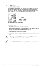
.... You can clear the CMOS memory of date, time, and system setup parameters by erasing the CMOS RTC RAM data. P8H67-M2/TPM/SI CLRTC 12 23 Normal (Default) Clear RTC P8H67-M2/TPM/SI Clear RTC RAM To erase the RTC RAM: 1. Plug the power cord and turn ON the computer. 4. Except when ...clearing the RTC RAM, never remove the cap on pins 2-3 for about 5-10 seconds, then move the jumper again to pins 1-2. 3. After clearing the CMOS, reinstall the battery. 1-8 ASUS P8H67-M2...
.... You can clear the CMOS memory of date, time, and system setup parameters by erasing the CMOS RTC RAM data. P8H67-M2/TPM/SI CLRTC 12 23 Normal (Default) Clear RTC P8H67-M2/TPM/SI Clear RTC RAM To erase the RTC RAM: 1. Plug the power cord and turn ON the computer. 4. Except when ...clearing the RTC RAM, never remove the cap on pins 2-3 for about 5-10 seconds, then move the jumper again to pins 1-2. 3. After clearing the CMOS, reinstall the battery. 1-8 ASUS P8H67-M2...
User Manual
Page 20
... 2. This 15-pin port is for details. 1-10 ASUS P8H67-M2 Series GND PRESENCE# SENSE1_RETUR SENSE2_RETUR AGND NC NC NC AAFP PIN 1 PIN 1 MIC2 MICPWR Line out_R NC Line out_L PORT1 L PORT1 R PORT2 R SENSE_SEND PORT2 L P8H67-M2/TPM/SI HD-audio-compliant Legacy AC'97 pin definition compliant definition P8H67-M2/TPM/SI Front panel audio connector • We recommend that...
... 2. This 15-pin port is for details. 1-10 ASUS P8H67-M2 Series GND PRESENCE# SENSE1_RETUR SENSE2_RETUR AGND NC NC NC AAFP PIN 1 PIN 1 MIC2 MICPWR Line out_R NC Line out_L PORT1 L PORT1 R PORT2 R SENSE_SEND PORT2 L P8H67-M2/TPM/SI HD-audio-compliant Legacy AC'97 pin definition compliant definition P8H67-M2/TPM/SI Front panel audio connector • We recommend that...
User Manual
Page 21
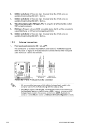
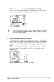
... the fan connectors on the fan connectors! 3. The signal is for a chassis-mounted intrusion detection sensor or switch. CHASSIS P8H67-M2/TPM/SI P8H67-M2/TPM/SI Chassis intrusion connector +5VSB_MB Chassis Signal GND Chapter 1: Product introduction 1-11 Insufficient air flow inside the system may damage the ...motherboard components. CPU_FAN CPU FAN PWM CPU FAN IN CPU FAN PWR GND P8H67-M2/TPM/SI CHA_FAN GND +12V Rotation P8H67-M2/TPM/SI Fan connectors Do not forget to connect the fan cables to use the chassis intrusion detection feature. Connect...
... the fan connectors on the fan connectors! 3. The signal is for a chassis-mounted intrusion detection sensor or switch. CHASSIS P8H67-M2/TPM/SI P8H67-M2/TPM/SI Chassis intrusion connector +5VSB_MB Chassis Signal GND Chapter 1: Product introduction 1-11 Insufficient air flow inside the system may damage the ...motherboard components. CPU_FAN CPU FAN PWM CPU FAN IN CPU FAN PWR GND P8H67-M2/TPM/SI CHA_FAN GND +12V Rotation P8H67-M2/TPM/SI Fan connectors Do not forget to connect the fan cables to use the chassis intrusion detection feature. Connect...
User Manual
Page 22
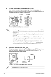
...the Recommended Power Supply Wattage Calculator at http://support.asus. Connect the S/PDIF Out module cable to this connector, then install the module to fit these connectors in only one orientation. ATX12V EATXPWR +12V DC +12V DC P8H67-M2/TPM/SI GND GND +3 Volts +12 Volts +12 Volts...) and provides a minimum power of the system chassis. +5V SPDIFOUT GND P8Q67-M DO/USB3/TPM SPDIF_OUT P8Q67-M DO/USB3/TPM Digital audio connector The S/PDIF module is purchased separately. 1-12 ASUS P8H67-M2 Series 4. Otherwise, the system will not boot up if the power is for your system, refer...
...the Recommended Power Supply Wattage Calculator at http://support.asus. Connect the S/PDIF Out module cable to this connector, then install the module to fit these connectors in only one orientation. ATX12V EATXPWR +12V DC +12V DC P8H67-M2/TPM/SI GND GND +3 Volts +12 Volts +12 Volts...) and provides a minimum power of the system chassis. +5V SPDIFOUT GND P8Q67-M DO/USB3/TPM SPDIF_OUT P8Q67-M DO/USB3/TPM Digital audio connector The S/PDIF module is purchased separately. 1-12 ASUS P8H67-M2 Series 4. Otherwise, the system will not boot up if the power is for your system, refer...
User Manual
Page 23
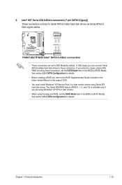
... ATA hard disk drives. See section 2.5.4 SATA Configuration for details. SATA6G_1 GND RSATA_TXP1 RSATA_TXN1 GND RSATA_RXP1 RSATA_RXN1 GND GND RSATA_RXN2 RSATA_RXP2 GND RSATA_TXN2 RSATA_TXP2 GND P8H67-M2/TPM/SI SATA6G_2 P8H67-M2/TPM/SI Intel® SATA 6.0Gb/s connectors • These connectors are using Windows® XP SP3 or later version. • When using these connectors. The Serial...
... ATA hard disk drives. See section 2.5.4 SATA Configuration for details. SATA6G_1 GND RSATA_TXP1 RSATA_TXN1 GND RSATA_RXP1 RSATA_RXN1 GND GND RSATA_RXN2 RSATA_RXP2 GND RSATA_TXN2 RSATA_TXP2 GND P8H67-M2/TPM/SI SATA6G_2 P8H67-M2/TPM/SI Intel® SATA 6.0Gb/s connectors • These connectors are using Windows® XP SP3 or later version. • When using these connectors. The Serial...
User Manual
Page 24
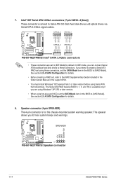
...connect Serial ATA boot/data hard disk drives to [AHCI Mode]. SPEAKER +5V GND GND Speaker Out P8H67-M2/TPM/SI PIN 1 P8H67-M2/TPM/SI Speaker connector 1-14 ASUS P8H67-M2 Series In IDE mode, you intend to create a Serial ATA RAID set using these connectors. See ...RSATA_TXP3 RSATA_TXN3 GND RSATA_RXP3 RSATA_RXN3 GND GND RSATA_RXN2 RSATA_RXP2 GND RSATA_TXN2 RSATA_TXP2 GND GND RSATA_RXN4 RSATA_RXP4 GND RSATA_TXN4 RSATA_TXP4 GND P8H67-M2/TPM/SI SATA3G_4 SATA3G_2 P8H67-M2/TPM/SI Intel® SATA 3.0Gb/s connectors • These connectors are using Windows® XP SP3 or later version...
...connect Serial ATA boot/data hard disk drives to [AHCI Mode]. SPEAKER +5V GND GND Speaker Out P8H67-M2/TPM/SI PIN 1 P8H67-M2/TPM/SI Speaker connector 1-14 ASUS P8H67-M2 Series In IDE mode, you intend to create a Serial ATA RAID set using these connectors. See ...RSATA_TXP3 RSATA_TXN3 GND RSATA_RXP3 RSATA_RXN3 GND GND RSATA_RXN2 RSATA_RXP2 GND RSATA_TXN2 RSATA_TXP2 GND GND RSATA_RXN4 RSATA_RXP4 GND RSATA_TXN4 RSATA_TXP4 GND P8H67-M2/TPM/SI SATA3G_4 SATA3G_2 P8H67-M2/TPM/SI Intel® SATA 3.0Gb/s connectors • These connectors are using Windows® XP SP3 or later version...
User Manual
Page 25
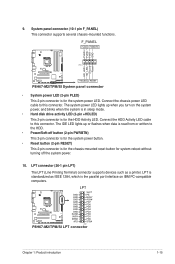
... activity LED (2-pin +HDLED) This 2-pin connector is the parallel port interface on IBM PC-compatible computers. Ground Reset PIN 1 P8H67-M2/TPM/SI +HDLED RESET P8H67-M2/TPM/SI System panel connector • System power LED (2-pin PLED) This 2-pin connector is for the chassis-mounted reset button for the system... SLCT GND PE GND BUSY GND ACK# GND PD7 GND PD6 GND PD5 GND PD4 GND PD3 P8H67-M2/TPM/SI SLIN# PD2 INIT# PD1 ERR# PD0 AFD STB# PIN 1 P8H67-M2/TPM/SI LPT connector Chapter 1: Product introduction 1-15 The system power LED lights up or flashes when data ...
... activity LED (2-pin +HDLED) This 2-pin connector is the parallel port interface on IBM PC-compatible computers. Ground Reset PIN 1 P8H67-M2/TPM/SI +HDLED RESET P8H67-M2/TPM/SI System panel connector • System power LED (2-pin PLED) This 2-pin connector is for the chassis-mounted reset button for the system... SLCT GND PE GND BUSY GND ACK# GND PD7 GND PD6 GND PD5 GND PD4 GND PD3 P8H67-M2/TPM/SI SLIN# PD2 INIT# PD1 ERR# PD0 AFD STB# PIN 1 P8H67-M2/TPM/SI LPT connector Chapter 1: Product introduction 1-15 The system power LED lights up or flashes when data ...
User Manual
Page 26
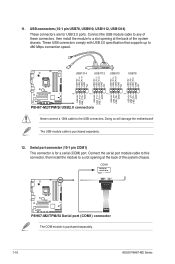
...COM1 PIN 1 P8H67-M2/TPM/SI P8H67-M2/TPM/SI Serial port (COM1) connector The COM module is purchased separately. 12. USB connectors (10-1 pin USB78, USB910, USB1112, USB1314) These connectors are for a serial (COM) port. The USB module cable is purchased separately. 1-16 ASUS P8H67-M2 Series 11. ...USB1314 USB1112 USB910 USB78 USB+5V USB_P14USB_P14+ GND NC USB+5V USB_P12USB_P12+ GND NC USB+5V USB_P10USB_P10+ GND NC USB+5V USB_P8USB_P8+ GND NC P8H67-M2/TPM/SI PIN 1 PIN 1 PIN 1 PIN 1 USB+5V...
...COM1 PIN 1 P8H67-M2/TPM/SI P8H67-M2/TPM/SI Serial port (COM1) connector The COM module is purchased separately. 12. USB connectors (10-1 pin USB78, USB910, USB1112, USB1314) These connectors are for a serial (COM) port. The USB module cable is purchased separately. 1-16 ASUS P8H67-M2 Series 11. ...USB1314 USB1112 USB910 USB78 USB+5V USB_P14USB_P14+ GND NC USB+5V USB_P12USB_P12+ GND NC USB+5V USB_P10USB_P10+ GND NC USB+5V USB_P8USB_P8+ GND NC P8H67-M2/TPM/SI PIN 1 PIN 1 PIN 1 PIN 1 USB+5V...

User Manual
Page 30
... Info MODEL: P8H67-M2/TPM/SI File Path: fs0:\ Drive fs0:\ VER: 0201 Folder Info 03/21/2011 10:23p 8388608 Exit DATE: 03/21/2011 P8H67M2T.ROM File Info MODEL: Help Info VER: DATE [Enter] Select or Load [Tab] Switch [Up/Down/PageUp/PageDown/Home/End] Move [Esc] Exit [F2] Backup 2-2 ASUS P8H67-M2 Series Always...
... Info MODEL: P8H67-M2/TPM/SI File Path: fs0:\ Drive fs0:\ VER: 0201 Folder Info 03/21/2011 10:23p 8388608 Exit DATE: 03/21/2011 P8H67M2T.ROM File Info MODEL: Help Info VER: DATE [Enter] Select or Load [Tab] Switch [Up/Down/PageUp/PageDown/Home/End] Move [Esc] Exit [F2] Backup 2-2 ASUS P8H67-M2 Series Always...
User Manual
Page 31
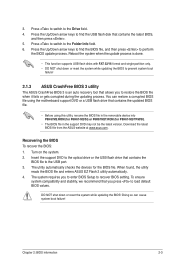
...drive that allows you to load default BIOS values. Recovering the BIOS To recover the BIOS: 1. The utility automatically checks the devices for P8H67-M2/TPM/SI). • The BIOS file in the support DVD may not be the latest version. When found, the utility reads the BIOS file and ...enters ASUS EZ Flash 2 utility automatically. 4. Press to switch to prevent system boot failure! 2.1.3 ASUS CrashFree BIOS 3 utility The ASUS CrashFree BIOS 3 is done. • This function supports USB flash disks with FAT 32/...
...drive that allows you to load default BIOS values. Recovering the BIOS To recover the BIOS: 1. The utility automatically checks the devices for P8H67-M2/TPM/SI). • The BIOS file in the support DVD may not be the latest version. When found, the utility reads the BIOS file and ...enters ASUS EZ Flash 2 utility automatically. 4. Press to switch to prevent system boot failure! 2.1.3 ASUS CrashFree BIOS 3 utility The ASUS CrashFree BIOS 3 is done. • This function supports USB flash disks with FAT 32/...
User Manual
Page 33
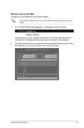
... any user-assigned filename with no more than eight alphanumeric characters for the filename and three alphanumeric characters for DOS V1.18 Current ROM BOARD: P8H67-M2/TPM/SI VER: 0201 DATE: 03/21/2011 Update ROM BOARD: Unknown VER: Unknown DATE: Unknown PATH: A:\ BIOS backup is not write-protected and has enough free...
... any user-assigned filename with no more than eight alphanumeric characters for the filename and three alphanumeric characters for DOS V1.18 Current ROM BOARD: P8H67-M2/TPM/SI VER: 0201 DATE: 03/21/2011 Update ROM BOARD: Unknown VER: Unknown DATE: Unknown PATH: A:\ BIOS backup is not write-protected and has enough free...

User Manual
Page 34
... version 1.04 or later, the utility automatically exits to the DOS prompt after updating the BIOS file if you have disconnected them. 2-6 ASUS P8H67-M2 Series BIOS Updater checks the selected BIOS file and prompts you sure to exit BIOS Updater. Select Yes and press . Select the Load Optimized... disk drives after updating BIOS. • Ensure to load the BIOS default settings to section 2.9 Exit menu for DOS V1.18 Current ROM BOARD: P8H67-M2/TPM/SI VER: 0201 DATE: 03/21/2011 Update ROM BOARD: Unknown VER: Unknown DATE: Unknown PATH: A:\ A: P8H67M2T.ROM 8388608 2011-03-21 17...
... version 1.04 or later, the utility automatically exits to the DOS prompt after updating the BIOS file if you have disconnected them. 2-6 ASUS P8H67-M2 Series BIOS Updater checks the selected BIOS file and prompts you sure to exit BIOS Updater. Select Yes and press . Select the Load Optimized... disk drives after updating BIOS. • Ensure to load the BIOS default settings to section 2.9 Exit menu for DOS V1.18 Current ROM BOARD: P8H67-M2/TPM/SI VER: 0201 DATE: 03/21/2011 Update ROM BOARD: Unknown VER: Unknown DATE: Unknown PATH: A:\ A: P8H67M2T.ROM 8388608 2011-03-21 17...
User Manual
Page 36
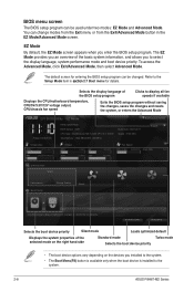
EZ Mode Friday [10/08/2010] P8H67-M2/TPM/SI BIOS Version : 0201 CPU Type : Intel(R) Core(TM) i5-2400 CPU @ 3.10GHz Total Memory : 1024 MB (DDR3 1333MHz) Build Date : 03/21/2011 Speed : 3100 ... appears when you installed to the system. • The Boot Menu(F8) button is available only when the boot device is installed to the system. 2-8 ASUS P8H67-M2 Series The default screen for details. To access the Advanced Mode, click Exit/Advanced Mode, then select Advanced Mode. Selects the display language of the...
EZ Mode Friday [10/08/2010] P8H67-M2/TPM/SI BIOS Version : 0201 CPU Type : Intel(R) Core(TM) i5-2400 CPU @ 3.10GHz Total Memory : 1024 MB (DDR3 1333MHz) Build Date : 03/21/2011 Speed : 3100 ... appears when you installed to the system. • The Boot Menu(F8) button is available only when the boot device is installed to the system. 2-8 ASUS P8H67-M2 Series The default screen for details. To access the Advanced Mode, click Exit/Advanced Mode, then select Advanced Mode. Selects the display language of the...
User Manual
Page 56
... Date : Apr. 11, 2011 Ver. 110101 EC Declaration of the FCC Rules. Country: TAIWAN Authorized representative in Europe: ASUS COMPUTER GmbH Address, City: HARKORT STR. 21-23, 40880 RATINGEN Country: GERMANY declare the following directives: 2004/108/EC-EMC... Supplementary Information: This device complies with the essential requirements of the following apparatus: Product name : Motherboard Model name : P8H67-M2/SI, P8H67-M2/TPM/SI conform with part 15 of Conformity We, the undersigned, Manufacturer: Address, City: ASUSTek COMPUTER INC. Operation is subject ...
... Date : Apr. 11, 2011 Ver. 110101 EC Declaration of the FCC Rules. Country: TAIWAN Authorized representative in Europe: ASUS COMPUTER GmbH Address, City: HARKORT STR. 21-23, 40880 RATINGEN Country: GERMANY declare the following directives: 2004/108/EC-EMC... Supplementary Information: This device complies with the essential requirements of the following apparatus: Product name : Motherboard Model name : P8H67-M2/SI, P8H67-M2/TPM/SI conform with part 15 of Conformity We, the undersigned, Manufacturer: Address, City: ASUSTek COMPUTER INC. Operation is subject ...


