
User Manual
Page 3
Contents Notices...v Safety information vi About this guide vi P7H55-M LE Series specifications summary viii Chapter 1: Product introduction 1.1 Before you proceed 1-1 1.2 Motherboard overview 1-2 1.2.1 Motherboard layout 1-2 1.2.2 Layout contents 1-2 ... panel ports 1-9 1.7.2 Internal connectors 1-10 1.8 Software support 1-17 1.8.1 Installing an operating system 1-17 1.8.2 Support DVD information 1-17 Chapter 2: BIOS information 2.1 Managing and updating your BIOS 2-1 2.1.1 ASUS Update 2-1 2.1.2 ASUS EZ Flash 2 2-2 2.1.3 ASUS BIOS Updater 2-3 2.1.4 ASUS CrashFree BIOS 3 2-6 iii
Contents Notices...v Safety information vi About this guide vi P7H55-M LE Series specifications summary viii Chapter 1: Product introduction 1.1 Before you proceed 1-1 1.2 Motherboard overview 1-2 1.2.1 Motherboard layout 1-2 1.2.2 Layout contents 1-2 ... panel ports 1-9 1.7.2 Internal connectors 1-10 1.8 Software support 1-17 1.8.1 Installing an operating system 1-17 1.8.2 Support DVD information 1-17 Chapter 2: BIOS information 2.1 Managing and updating your BIOS 2-1 2.1.1 ASUS Update 2-1 2.1.2 ASUS EZ Flash 2 2-2 2.1.3 ASUS BIOS Updater 2-3 2.1.4 ASUS CrashFree BIOS 3 2-6 iii
User Manual
Page 4
Contents 2.2 BIOS setup program 2-7 2.3 Main menu 2-8 2.3.1 System Time [xx:xx:xx 2-8 2.3.2 System Date [Day xx/xx/xxxx 2-8 2.3.3 Legacy Diskette A [1.44M, 3.5 in 2-8 2.3.4 Language [English 2-8 2.3.5 SATA 1-6 ...2.6 Boot menu 2-17 2.6.1 Boot Device Priority 2-17 2.6.2 Boot Settings Configuration 2-17 2.6.3 Security 2-18 2.7 Tools menu 2-19 2.8 Exit menu 2-20 P7P55/P7H57/P7H55 series motherboardsinstallation notices.......... 2-21 Intel® LGA1156 processor and chipset combination instruction.. 2-21 Memory configuration 2-21 Configurations for the PCI Express x16 slots 2-21 iv
Contents 2.2 BIOS setup program 2-7 2.3 Main menu 2-8 2.3.1 System Time [xx:xx:xx 2-8 2.3.2 System Date [Day xx/xx/xxxx 2-8 2.3.3 Legacy Diskette A [1.44M, 3.5 in 2-8 2.3.4 Language [English 2-8 2.3.5 SATA 1-6 ...2.6 Boot menu 2-17 2.6.1 Boot Device Priority 2-17 2.6.2 Boot Settings Configuration 2-17 2.6.3 Security 2-18 2.7 Tools menu 2-19 2.8 Exit menu 2-20 P7P55/P7H57/P7H55 series motherboardsinstallation notices.......... 2-21 Intel® LGA1156 processor and chipset combination instruction.. 2-21 Memory configuration 2-21 Configurations for the PCI Express x16 slots 2-21 iv
User Manual
Page 6
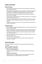
...power supply is set to the correct voltage in any area where it supports. • Chapter 2: BIOS information This chapter tells how to change system settings through the BIOS Setup menus. Do not place the product in your retailer. vi Contact a qualified service technician or ...the power supply is organized This guide contains the following parts: • Chapter 1: Product introduction This chapter describes the features of the BIOS parameters are unplugged. • Seek professional assistance before using an adapter or extension cord. How this guide This user guide contains the ...
...power supply is set to the correct voltage in any area where it supports. • Chapter 2: BIOS information This chapter tells how to change system settings through the BIOS Setup menus. Do not place the product in your retailer. vi Contact a qualified service technician or ...the power supply is organized This guide contains the following parts: • Chapter 1: Product introduction This chapter describes the features of the BIOS parameters are unplugged. • Seek professional assistance before using an adapter or extension cord. How this guide This user guide contains the ...
User Manual
Page 8
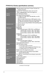
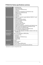
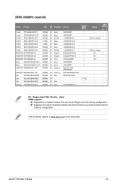
... 12 x USB 2.0/1.1 ports (6 ports at the mid-board, 6 ports at the back panel) ASUS CrashFree BIOS 3 Anti-Surge protection ASUS EZ Flash 2 ASUS Q-Fan 2 ASUS AI NET 2 ASUS MyLogo 2 (continued on the next page) viii resolution: 1920 x 1200 @60Hz - resolution: 2048 x 1536 @75Hz P7H55-M LX: Multi-VGA output support: DVI-D, and RGB ports - We recommend a maximum of...
... 12 x USB 2.0/1.1 ports (6 ports at the mid-board, 6 ports at the back panel) ASUS CrashFree BIOS 3 Anti-Surge protection ASUS EZ Flash 2 ASUS Q-Fan 2 ASUS AI NET 2 ASUS MyLogo 2 (continued on the next page) viii resolution: 1920 x 1200 @60Hz - resolution: 2048 x 1536 @75Hz P7H55-M LX: Multi-VGA output support: DVI-D, and RGB ports - We recommend a maximum of...
User Manual
Page 9
... x S/PDIF Out connector (for P7H55-M LE and P7H55-M LX only) 1 x COM connector (for P7H55-M LE and P7H55-M LX only) 1 x IDE connector (for P7H55-M LE only) 1 x Floppy disk drive connector (for P7H55-M LE only) 1 x LPT connector (for P7H55-M LE only) 64 Mb Flash ROM, AMI BIOS, PnP, DMI v2.0, WfM ...2.0, ACPI v2.0a, SM BIOS v2.5 WOL, PXE, PME Wake up, WOR by Ring 2 x Serial ATA cables 1 x I/O shield 1 x IDE cable (for P7H55-M LE only) 1 x User Manual 1 x Support DVD Drivers ASUS PC Probe II ASUS...
... x S/PDIF Out connector (for P7H55-M LE and P7H55-M LX only) 1 x COM connector (for P7H55-M LE and P7H55-M LX only) 1 x IDE connector (for P7H55-M LE only) 1 x Floppy disk drive connector (for P7H55-M LE only) 1 x LPT connector (for P7H55-M LE only) 64 Mb Flash ROM, AMI BIOS, PnP, DMI v2.0, WfM ...2.0, ACPI v2.0a, SM BIOS v2.5 WOL, PXE, PME Wake up, WOR by Ring 2 x Serial ATA cables 1 x I/O shield 1 x IDE cable (for P7H55-M LE only) 1 x User Manual 1 x Support DVD Drivers ASUS PC Probe II ASUS...
User Manual
Page 11
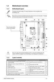
... power connectors (24-pin EATXPWR, 4-pin ATX12V) 3. Front panel audio connector (10-1 pin AAFP) 1-16 Page 1-11 1-1 1-12 1-8 1-10 1-11 1-14 ASUS P7H55-M LE Series 1-2 Ensure that you install the motherboard into the holes indicated by circles to secure the motherboard to the rear part of the chassis...FLOPPY LAN1_USB12 CHA_FAN AUDIO RTL 8112L VIA VT1708S AAFP CPU_FAN ICS 954 A4 Lithium Cell CMOS Power PCIEX16 P7H55-M LE PCI1 PCI2 PCIEX4_1 SPDIF_OUT USB1112 USB910 Intel® H55 64Mb BIOS SATA1 SATA2 SATA3 SATA4 USB78 CLRTC SATA5 SATA6 SB_PWR F_PANEL 2 8 9 10 15 14 13 ...
... power connectors (24-pin EATXPWR, 4-pin ATX12V) 3. Front panel audio connector (10-1 pin AAFP) 1-16 Page 1-11 1-1 1-12 1-8 1-10 1-11 1-14 ASUS P7H55-M LE Series 1-2 Ensure that you install the motherboard into the holes indicated by circles to secure the motherboard to the rear part of the chassis...FLOPPY LAN1_USB12 CHA_FAN AUDIO RTL 8112L VIA VT1708S AAFP CPU_FAN ICS 954 A4 Lithium Cell CMOS Power PCIEX16 P7H55-M LE PCI1 PCI2 PCIEX4_1 SPDIF_OUT USB1112 USB910 Intel® H55 64Mb BIOS SATA1 SATA2 SATA3 SATA4 USB78 CLRTC SATA5 SATA6 SB_PWR F_PANEL 2 8 9 10 15 14 13 ...
User Manual
Page 13
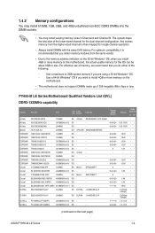
...Kit of 3) SS - - For optimum compatibility, it is then mapped for the dual-channel configuration. APACER AM5D5808DEWSBG - - - - - - - - - - Timing DIMM (BIOS) 8-8-8-24 8-8-8-24 9-9-9-24 9-9-9-24 9-9-9-24 9-9-9-24 9 9-9-9-24 9-9-9-24 9 6-6-6-20 9 6-6-6-20 6-6-6-20 7-7-7-24 - - 7-7-7-18 9-9-9-24 Voltage DIMM Support A* B* - ...Chip DS Brand Chip No. Use a maximum of 3GB system memory if you install 4GB or more memory on the next page) ASUS P7H55-M LE Series 1-4 Corsair - - - - - - - Any excess memory from the same vendor. • Due to ...
...Kit of 3) SS - - For optimum compatibility, it is then mapped for the dual-channel configuration. APACER AM5D5808DEWSBG - - - - - - - - - - Timing DIMM (BIOS) 8-8-8-24 8-8-8-24 9-9-9-24 9-9-9-24 9-9-9-24 9-9-9-24 9 9-9-9-24 9-9-9-24 9 6-6-6-20 9 6-6-6-20 6-6-6-20 7-7-7-24 - - 7-7-7-18 9-9-9-24 Voltage DIMM Support A* B* - ...Chip DS Brand Chip No. Use a maximum of 3GB system memory if you install 4GB or more memory on the next page) ASUS P7H55-M LE Series 1-4 Corsair - - - - - - - Any excess memory from the same vendor. • Due to ...
User Manual
Page 14
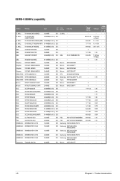
... Samsung K4B1G0846D-HCH9 Samsung SEC 846 HCH9 K4B1G08460 Samsung SEC 913 HCH9 K4B1G0846E Samsung K4B1G0846D-HCH9 Samsung SEC 913 HCH9 K4B1G0846E Micron 9GF27D9KPT Timing DIMM (BIOS) - Voltage - DDR3-1333MHz capability Vendor G.SKILL G.SKILL G.SKILL G.SKILL G.SKILL GEIL GEIL GEIL Part No.
... Samsung K4B1G0846D-HCH9 Samsung SEC 846 HCH9 K4B1G08460 Samsung SEC 913 HCH9 K4B1G0846E Samsung K4B1G0846D-HCH9 Samsung SEC 913 HCH9 K4B1G0846E Micron 9GF27D9KPT Timing DIMM (BIOS) - Voltage - DDR3-1333MHz capability Vendor G.SKILL G.SKILL G.SKILL G.SKILL G.SKILL GEIL GEIL GEIL Part No.
User Manual
Page 15
... for the latest QVL. DDR3-1066MHz capability Vendor Part No. Single-sided / DS - ASUS P7H55-M LE Series 1-6 SS Micron DS Micron SS ELPIDA SS Elpida SS Elpida DS Elpida DS ELPIDA SS Kingston...-AC-E J5308BASE-AC-E J5308BASE-AC-E J1108EDSE-DJ-F D1288JEKAPGA7U D1288JEKAPGA7U H5TQ2G83AFR 9GF22D9KPT 9HF22D9KPT SEC 901 HCF8 K4B1G0846E 846 K4B2G0846B-HCF8 N2CB1G80CN-BE H5TQ1G83AFP G7C Timing DIMM (BIOS) 7 7 7 7 7 7 7 - 7-7-7-20 - Voltage DIMM Support A* C* - •• - •• 1.35V(low voltage) • • - • - •• - •• 1.35V(low ...
... for the latest QVL. DDR3-1066MHz capability Vendor Part No. Single-sided / DS - ASUS P7H55-M LE Series 1-6 SS Micron DS Micron SS ELPIDA SS Elpida SS Elpida DS Elpida DS ELPIDA SS Kingston...-AC-E J5308BASE-AC-E J5308BASE-AC-E J1108EDSE-DJ-F D1288JEKAPGA7U D1288JEKAPGA7U H5TQ2G83AFR 9GF22D9KPT 9HF22D9KPT SEC 901 HCF8 K4B1G0846E 846 K4B2G0846B-HCF8 N2CB1G80CN-BE H5TQ1G83AFP G7C Timing DIMM (BIOS) 7 7 7 7 7 7 7 - 7-7-7-20 - Voltage DIMM Support A* C* - •• - •• 1.35V(low voltage) • • - • - •• - •• 1.35V(low ...
User Manual
Page 16
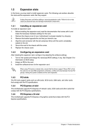
...chassis). 3. See Chapter 2 for the expansion card. When using PCI cards on the slot. 5. Secure the card to use. 4. Turn on BIOS setup. 2. Remove the bracket opposite the slot that comes with the screw. 6. Install the software drivers for information on the system and change ...the necessary BIOS settings, if any. Assign an IRQ to the card. 3. Before installing the expansion card, read the documentation that you physical injury and...
...chassis). 3. See Chapter 2 for the expansion card. When using PCI cards on the slot. 5. Secure the card to use. 4. Turn on BIOS setup. 2. Remove the bracket opposite the slot that comes with the screw. 6. Install the software drivers for information on the system and change ...the necessary BIOS settings, if any. Assign an IRQ to the card. 3. Before installing the expansion card, read the documentation that you physical injury and...
User Manual
Page 17
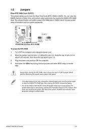
...CMOS RTC RAM data. Shut down the key during the boot process and enter BIOS setup to pins 2-3. You can clear the CMOS memory of date, time, and system setup parameters by erasing the CMOS RTC RAM data. ASUS P7H55-M LE Series 1-8 Removing the cap will cause system boot failure! • If... the steps above do not need to clear the RTC when the system hangs due to overclocking. Hold down and cut off the AC power, then reboot the system, the BIOS automatically resets parameter ...
...CMOS RTC RAM data. Shut down the key during the boot process and enter BIOS setup to pins 2-3. You can clear the CMOS memory of date, time, and system setup parameters by erasing the CMOS RTC RAM data. ASUS P7H55-M LE Series 1-8 Removing the cap will cause system boot failure! • If... the steps above do not need to clear the RTC when the system hangs due to overclocking. Hold down and cut off the AC power, then reboot the system, the BIOS automatically resets parameter ...

User Manual
Page 23
...The FDD cable is set the item to this connector, ensure that supports either High Definition Audio or AC`97 audio standard. P7H55-M LE Floppy disk drive connector ASUS P7H55-M LE Series 1-14 If you want to connect an AC97 front panel audio module to [AC97]. 7. SENSE2_RETUR SENSE1_RETUR PRESENCE#... compliant definition P7H55-M LE Front panel audio connector If you want to connect a high-definition front panel audio module to this connector, set to PIN 1. Insert one end of the front panel audio I /O module that the Front Panel Type item in the BIOS is purchased separately...
...The FDD cable is set the item to this connector, ensure that supports either High Definition Audio or AC`97 audio standard. P7H55-M LE Floppy disk drive connector ASUS P7H55-M LE Series 1-14 If you want to connect an AC97 front panel audio module to [AC97]. 7. SENSE2_RETUR SENSE1_RETUR PRESENCE#... compliant definition P7H55-M LE Front panel audio connector If you want to connect a high-definition front panel audio module to this connector, set to PIN 1. Insert one end of the front panel audio I /O module that the Front Panel Type item in the BIOS is purchased separately...
User Manual
Page 27
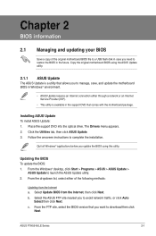
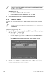
... avoid network traffic, or click Auto Select then click Next. Select Update BIOS from the Internet a. b. Select the ASUS FTP site nearest you to launch the ASUS Update utility. 2. From the FTP site, select the BIOS version that comes with the motherboard package. c. ASUS P7H55-M LE Series 2-1 Place the support DVD into the optical drive. Chapter...
... avoid network traffic, or click Auto Select then click Next. Select Update BIOS from the Internet a. b. Select the ASUS FTP site nearest you to launch the ASUS Update utility. 2. From the FTP site, select the BIOS version that comes with the motherboard package. c. ASUS P7H55-M LE Series 2-1 Place the support DVD into the optical drive. Chapter...
User Manual
Page 28
...press to switch between drives until the correct BIOS file is found . Follow the onscreen instructions to update the BIOS without using an OS‑based utility. Press to enable it. ASUSTek EZ Flash 2 BIOS ROM Utility V4.14 Current ROM BOARD: P7H55-M LX VER: 0301 (H:00 B:00) ... 2 in either of updating itself through the Internet. Updating from a file, then click Next. Locate the BIOS file from the ASUS website at www.asus.com. When the correct BIOS file is found , EZ Flash 2 performs the BIOS update process and automatically reboots the system when done. 2-2 Chapter...
...press to switch between drives until the correct BIOS file is found . Follow the onscreen instructions to update the BIOS without using an OS‑based utility. Press to enable it. ASUSTek EZ Flash 2 BIOS ROM Utility V4.14 Current ROM BOARD: P7H55-M LX VER: 0301 (H:00 B:00) ... 2 in either of updating itself through the Internet. Updating from a file, then click Next. Locate the BIOS file from the ASUS website at www.asus.com. When the correct BIOS file is found , EZ Flash 2 performs the BIOS update process and automatically reboots the system when done. 2-2 Chapter...
User Manual
Page 29
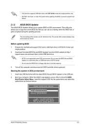
... to a floppy disk due to prevent system boot failure! 2.1.3 ASUS BIOS Updater The ASUS BIOS Updater allows you can use as a backup when the BIOS fails or gets corrupted during the updating process. Boot your computer. When the ASUS Logo appears, press to boot using defaults ASUS P7H55-M LE Series 2-3 Please select boot device: SATA:XXXXXXXXXXXXXXXX CDROM:XXXXXXXXXXXXXXX...
... to a floppy disk due to prevent system boot failure! 2.1.3 ASUS BIOS Updater The ASUS BIOS Updater allows you can use as a backup when the BIOS fails or gets corrupted during the updating process. Boot your computer. When the ASUS Logo appears, press to boot using defaults ASUS P7H55-M LE Series 2-3 Please select boot device: SATA:XXXXXXXXXXXXXXXX CDROM:XXXXXXXXXXXXXXX...
User Manual
Page 30
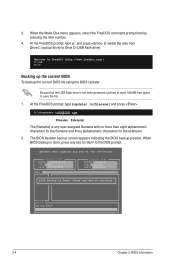
... for DOS V1.00b [09/06/22] Current ROM BOARD: P7H55-M LX VER: 0301 DATE: 07/12/2010 Update ROM BOARD: Unknown VER: Unknown DATE: Unknown PATH: A:\ BIOS backup is done! 3. C:\>d: D:\> Backing up the current BIOS To backup the current BIOS file using the BIOS Updater Ensure that the USB flash drive is done, press...
... for DOS V1.00b [09/06/22] Current ROM BOARD: P7H55-M LX VER: 0301 DATE: 07/12/2010 Update ROM BOARD: Unknown VER: Unknown DATE: Unknown PATH: A:\ BIOS backup is done! 3. C:\>d: D:\> Backing up the current BIOS To backup the current BIOS file using the BIOS Updater Ensure that the USB flash drive is done, press...
User Manual
Page 31
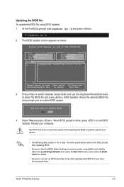
...if you have disconnected them. Select the Load Setup Defaults item under the Exit BIOS menu. D:\>bupdater /pc /g 2. ASUS P7H55-M LE Series 2-5 Updating the BIOS file To update the BIOS file using BIOS Updater 1. The BIOS Updater screen appears as below. Yes No 4. See section 2.8 Exit menu for... DOS V1.00b [09/06/22] Current ROM BOARD: P7H55-M LX VER: 0301 DATE: 07/...
...if you have disconnected them. Select the Load Setup Defaults item under the Exit BIOS menu. D:\>bupdater /pc /g 2. ASUS P7H55-M LE Series 2-5 Updating the BIOS file To update the BIOS file using BIOS Updater 1. The BIOS Updater screen appears as below. Yes No 4. See section 2.8 Exit menu for... DOS V1.00b [09/06/22] Current ROM BOARD: P7H55-M LX VER: 0301 DATE: 07/...
User Manual
Page 32
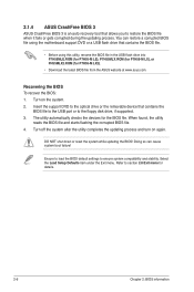
... flash drive into P7H55MLE.ROM (for P7H55-M LE), P7H55MLX.ROM (for P7H55-M LX), or PH55MLX2.ROM (for P7H55-M LX2). • Download the latest BIOS file from the ASUS website at www.asus.com. Turn off the system after the utility completes the updating process and turn on the system. 2. 2.1.4 ASUS CrashFree BIOS 3 ASUS CrashFree BIOS 3 is an auto recovery tool...
... flash drive into P7H55MLE.ROM (for P7H55-M LE), P7H55MLX.ROM (for P7H55-M LX), or PH55MLX2.ROM (for P7H55-M LX2). • Download the latest BIOS file from the ASUS website at www.asus.com. Turn off the system after the utility completes the updating process and turn on the system. 2. 2.1.4 ASUS CrashFree BIOS 3 ASUS CrashFree BIOS 3 is an auto recovery tool...
User Manual
Page 33
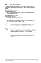
... compatibility and stability. Do this motherboard. Select the Load Setups Default item under the Exit Menu. ASUS P7H55-M LE Series 2-7 Entering BIOS Setup at startup To enter BIOS Setup at www.asus.com to your screen. • Visit the ASUS website at startup: • Press during the Power-On Self Test (POST). See section 2.8 Exit Menu...
... compatibility and stability. Do this motherboard. Select the Load Setups Default item under the Exit Menu. ASUS P7H55-M LE Series 2-7 Entering BIOS Setup at startup To enter BIOS Setup at www.asus.com to your screen. • Visit the ASUS website at startup: • Press during the Power-On Self Test (POST). See section 2.8 Exit Menu...
User Manual
Page 34
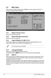
... [00:31:48] [Fri 04/10/2009] [1.44M, 3.5 in BIOS. Select Screen Select Item +- Configuration options: [Disabled] [360K, 5.25 in.] [1.2M , 5.25 in.] [720K , 3.5 in.] [1.44M, 3.5 in.] [2.88M, 3.5 in.] This item appears only on P7H55-M LE. 2.3.4 Language [English] Allows you to choose the display language... Time [xx:xx:xx] Allows you to set the system date. 2.3.3 Legacy Diskette A [1.44M, 3.5 in the system. 2-8 Chapter 2: BIOS information The BIOS automatically detects the values opposite the dimmed items (Device, Vendor, Size, LBA Mode, Block Mode, PIO Mode, Async DMA, Ultra DMA, and...
... [00:31:48] [Fri 04/10/2009] [1.44M, 3.5 in BIOS. Select Screen Select Item +- Configuration options: [Disabled] [360K, 5.25 in.] [1.2M , 5.25 in.] [720K , 3.5 in.] [1.44M, 3.5 in.] [2.88M, 3.5 in.] This item appears only on P7H55-M LE. 2.3.4 Language [English] Allows you to choose the display language... Time [xx:xx:xx] Allows you to set the system date. 2.3.3 Legacy Diskette A [1.44M, 3.5 in the system. 2-8 Chapter 2: BIOS information The BIOS automatically detects the values opposite the dimmed items (Device, Vendor, Size, LBA Mode, Block Mode, PIO Mode, Async DMA, Ultra DMA, and...


