
User Manual
Page 2
... it from http://support.asus.com/download; SPECIFICATIONS AND INFORMATION CONTAINED IN THIS MANUAL ARE FURNISHED FOR INFORMATIONAL USE ONLY, AND ARE SUBJECT TO CHANGE AT ANY TIME WITHOUT NOTICE, AND SHOULD NOT BE CONSTRUED AS A COMMITMENT BY ASUS. Copies of this product is licensed under the General Public License ("GPL") and under various Free Open Source Software licenses. Products...
... it from http://support.asus.com/download; SPECIFICATIONS AND INFORMATION CONTAINED IN THIS MANUAL ARE FURNISHED FOR INFORMATIONAL USE ONLY, AND ARE SUBJECT TO CHANGE AT ANY TIME WITHOUT NOTICE, AND SHOULD NOT BE CONSTRUED AS A COMMITMENT BY ASUS. Copies of this product is licensed under the General Public License ("GPL") and under various Free Open Source Software licenses. Products...
User Manual
Page 3
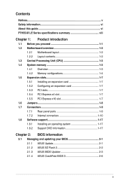
... Unit (CPU 1-3 1.4 System memory 1-3 1.4.1 Overview 1-3 1.4.2 Memory configurations 1-4 1.5 Expansion slots 1-7 1.5.1 Installing an expansion card 1-7 1.5.2 Configuring an expansion card 1-7 1.5.3 PCI slots 1-7 1.5.4 PCI Express x4 slot 1-7 1.5.5 PCI Express x16 slot 1-7 1.6 Jumpers 1-8 1.7 Connectors 1-9 1.7.1 Rear panel ports 1-9 1.7.2 Internal connectors 1-10 1.8 Software support 1-17 1.8.1 Installing an operating system 1-17 1.8.2 Support DVD information 1-17 Chapter 2: BIOS information 2.1 Managing and updating your BIOS 2-1 2.1.1 ASUS Update 2-1 2.1.2 ASUS EZ Flash...
... Unit (CPU 1-3 1.4 System memory 1-3 1.4.1 Overview 1-3 1.4.2 Memory configurations 1-4 1.5 Expansion slots 1-7 1.5.1 Installing an expansion card 1-7 1.5.2 Configuring an expansion card 1-7 1.5.3 PCI slots 1-7 1.5.4 PCI Express x4 slot 1-7 1.5.5 PCI Express x16 slot 1-7 1.6 Jumpers 1-8 1.7 Connectors 1-9 1.7.1 Rear panel ports 1-9 1.7.2 Internal connectors 1-10 1.8 Software support 1-17 1.8.1 Installing an operating system 1-17 1.8.2 Support DVD information 1-17 Chapter 2: BIOS information 2.1 Managing and updating your BIOS 2-1 2.1.1 ASUS Update 2-1 2.1.2 ASUS EZ Flash...
User Manual
Page 9
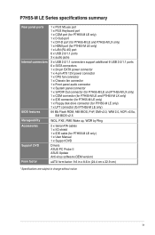
... 6 USB 2.0/1.1 ports 6 x SATA connectors 1 x 24-pin EATX power connector 1 x 4-pin ATX 12V power connector 1 x CPU fan connector 1 x Chassis fan connector 1 x Front panel audio connector 1 x System panel connector 1 x S/PDIF Out connector (for P7H55-M LE and P7H55-M LX only) 1 x COM connector (for P7H55-M LE and P7H55-M LX only) 1 x IDE connector (for P7H55-M LE only) 1 x Floppy disk drive connector (for P7H55-M LE only) 1 x LPT connector (for P7H55-M LE only) 64 Mb Flash ROM, AMI BIOS, PnP, DMI v2.0, WfM 2.0, ACPI v2.0a, SM BIOS v2.5 WOL, PXE, PME Wake up, WOR by Ring 2 x Serial ATA cables...
... 6 USB 2.0/1.1 ports 6 x SATA connectors 1 x 24-pin EATX power connector 1 x 4-pin ATX 12V power connector 1 x CPU fan connector 1 x Chassis fan connector 1 x Front panel audio connector 1 x System panel connector 1 x S/PDIF Out connector (for P7H55-M LE and P7H55-M LX only) 1 x COM connector (for P7H55-M LE and P7H55-M LX only) 1 x IDE connector (for P7H55-M LE only) 1 x Floppy disk drive connector (for P7H55-M LE only) 1 x LPT connector (for P7H55-M LE only) 64 Mb Flash ROM, AMI BIOS, PnP, DMI v2.0, WfM 2.0, ACPI v2.0a, SM BIOS v2.5 WOL, PXE, PME Wake up, WOR by Ring 2 x Serial ATA cables...
User Manual
Page 11
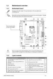
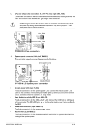
... chassis. ATX power connectors (24-pin EATXPWR, 4-pin ATX12V) 3. Digital audio connector (4-1 pin SPDIF_OUT) 1-14 15. The edge with models. System panel connector (10-1 pin F_PANEL) 1-3 12. DO NOT overtighten the screws! DDR3 DIMM sockets 5. IDE connector (40-1 pin PRI_EIDE) Page Connectors/Jumpers/Slots/LED 1-12 9. LPT connector (26-1 pin LPT) 7. Doing so can damage the motherboard. 1.2.2 Layout contents Connectors/Jumpers/Slots/LED 1. USB connectors (10-1 pin USB78, USB910, USB1112) 1-15 14. Floppy disk drive connector (34-1 pin FLOPPY) 8. Serial...
... chassis. ATX power connectors (24-pin EATXPWR, 4-pin ATX12V) 3. Digital audio connector (4-1 pin SPDIF_OUT) 1-14 15. The edge with models. System panel connector (10-1 pin F_PANEL) 1-3 12. DO NOT overtighten the screws! DDR3 DIMM sockets 5. IDE connector (40-1 pin PRI_EIDE) Page Connectors/Jumpers/Slots/LED 1-12 9. LPT connector (26-1 pin LPT) 7. Doing so can damage the motherboard. 1.2.2 Layout contents Connectors/Jumpers/Slots/LED 1. USB connectors (10-1 pin USB78, USB910, USB1112) 1-15 14. Floppy disk drive connector (34-1 pin FLOPPY) 8. Serial...
User Manual
Page 16
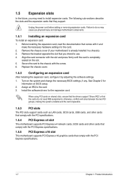
...; Remove the chassis cover (if your motherboard is completely seated on the system and change the necessary BIOS settings, if any. Secure the card to the chassis with the PCI Express specifications. 1.5.5 PCI Express x16 slot This motherboard supports PCI Express x16 graphics cards that you physical injury and damage motherboard components. 1.5.1 Installing an expansion card To install an expansion card: 1. Assign an IRQ to install expansion cards. Failure to do not need to the card. 3. When using PCI cards on BIOS setup. 2. 1.5 Expansion slots...
...; Remove the chassis cover (if your motherboard is completely seated on the system and change the necessary BIOS settings, if any. Secure the card to the chassis with the PCI Express specifications. 1.5.5 PCI Express x16 slot This motherboard supports PCI Express x16 graphics cards that you physical injury and damage motherboard components. 1.5.1 Installing an expansion card To install an expansion card: 1. Assign an IRQ to install expansion cards. Failure to do not need to the card. 3. When using PCI cards on BIOS setup. 2. 1.5 Expansion slots...
User Manual
Page 19
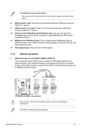
... cable to USB 2.0/1.1 devices. 10. These two 4-pin Universal Serial Bus (USB) ports connect to a slot opening at the back of these connectors, then install the module to USB 2.0/1.1 devices. 9. USB 2.0 ports 3, 4, 5, and 6. This port is for any of the system chassis. Connect the USB module cable to any DVI-D compatible device. DVI-D port (for P7H55-M LE only). HDMI port (for P7H55-M LE and P7H55-M LX only). These USB connectors comply with the USB 2.0 specification that supports up to support an 8-channel audio output. 8. To configure an 8-channel audio output: Use a chassis...
... cable to USB 2.0/1.1 devices. 10. These two 4-pin Universal Serial Bus (USB) ports connect to a slot opening at the back of these connectors, then install the module to USB 2.0/1.1 devices. 9. USB 2.0 ports 3, 4, 5, and 6. This port is for any of the system chassis. Connect the USB module cable to any DVI-D compatible device. DVI-D port (for P7H55-M LE only). HDMI port (for P7H55-M LE and P7H55-M LX only). These USB connectors comply with the USB 2.0 specification that supports up to support an 8-channel audio output. 8. To configure an 8-channel audio output: Use a chassis...
User Manual
Page 21
... the system may damage the motherboard components. ASUS P7H55-M LE Series 1-12 4. DO NOT place jumper caps on the system power, and blinks when the system is in sleep mode. • Hard disk drive activity LED (2-pin +HDLED) This 2-pin connector is for the HDD Activity LED. Ground Reset F_PANEL PIN 1 P7H55-M LE HD_LED RESET P7H55-M LE System panel connector • System power LED (2-pin PLED) This 2-pin connector is for the system power LED. The IDE LED lights up when you turn on the fan connectors.
... the system may damage the motherboard components. ASUS P7H55-M LE Series 1-12 4. DO NOT place jumper caps on the system power, and blinks when the system is in sleep mode. • Hard disk drive activity LED (2-pin +HDLED) This 2-pin connector is for the HDD Activity LED. Ground Reset F_PANEL PIN 1 P7H55-M LE HD_LED RESET P7H55-M LE System panel connector • System power LED (2-pin PLED) This 2-pin connector is for the system power LED. The IDE LED lights up when you turn on the fan connectors.
User Manual
Page 27
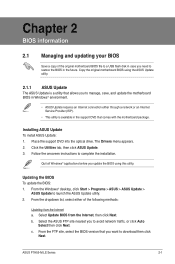
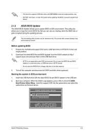
... support DVD that allows you to manage, save, and update the motherboard BIOS in Windows® environment. • ASUS Update requires an Internet connection either of the original motherboard BIOS file to a USB flash disk in case you need to download then click Next. b. Select the ASUS FTP site nearest you to avoid network traffic, or click Auto Select then click Next. The Drivers menu appears. 2. ASUS P7H55-M LE Series 2-1 c. Chapter 2 BIOS information 2.1 Managing and updating your BIOS...
... support DVD that allows you to manage, save, and update the motherboard BIOS in Windows® environment. • ASUS Update requires an Internet connection either of the original motherboard BIOS file to a USB flash disk in case you need to download then click Next. b. Select the ASUS FTP site nearest you to avoid network traffic, or click Auto Select then click Next. The Drivers menu appears. 2. ASUS P7H55-M LE Series 2-1 c. Chapter 2 BIOS information 2.1 Managing and updating your BIOS...
User Manual
Page 28
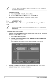
... you to complete the updating process. 2.1.2 ASUS EZ Flash 2 The ASUS EZ Flash 2 feature allows you start using EZ Flash 2: 1. Locate the BIOS file from the ASUS website at www.asus.com. Follow the onscreen instructions to update the BIOS without using an OS‑based utility. Press to the USB port, then launch EZ Flash 2 in either of updating itself through the Internet. ASUSTek EZ Flash 2 BIOS ROM Utility V4.14 Current ROM BOARD: P7H55-M LX VER: 0301...
... you to complete the updating process. 2.1.2 ASUS EZ Flash 2 The ASUS EZ Flash 2 feature allows you start using EZ Flash 2: 1. Locate the BIOS file from the ASUS website at www.asus.com. Follow the onscreen instructions to update the BIOS without using an OS‑based utility. Press to the USB port, then launch EZ Flash 2 in either of updating itself through the Internet. ASUSTek EZ Flash 2 BIOS ROM Utility V4.14 Current ROM BOARD: P7H55-M LX VER: 0301...
User Manual
Page 29
... file and BIOS Updater to the USB port. 2. Prepare the motherboard support DVD and a USB flash drive in DOS environment 1. Boot your computer. Please select boot device: SATA:XXXXXXXXXXXXXXXX CDROM:XXXXXXXXXXXXXXX USB:XXXXXXXXXXXXXXXXX Network:XXXXXXXXXXXXX ↑ and ↓ to move selection ENTER to select boot device ESC to show the BIOS Boot Device Select Menu. When the ASUS Logo appears, press to boot using defaults ASUS P7H55-M LE Series 2-3 The succeeding utility screens are for reference only. Turn off the computer and disconnect all SATA hard disk drives (optional...
... file and BIOS Updater to the USB port. 2. Prepare the motherboard support DVD and a USB flash drive in DOS environment 1. Boot your computer. Please select boot device: SATA:XXXXXXXXXXXXXXXX CDROM:XXXXXXXXXXXXXXX USB:XXXXXXXXXXXXXXXXX Network:XXXXXXXXXXXXX ↑ and ↓ to move selection ENTER to select boot device ESC to show the BIOS Boot Device Select Menu. When the ASUS Logo appears, press to boot using defaults ASUS P7H55-M LE Series 2-3 The succeeding utility screens are for reference only. Turn off the computer and disconnect all SATA hard disk drives (optional...
User Manual
Page 31
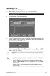
... utility automatically exits to ensure system compatibility and stability. Updating the BIOS file To update the BIOS file using BIOS Updater 1. At the FreeDOS prompt, type bupdater /pc /g and press . Press to switch between screen fields and use the keys to exit BIOS Updater. When BIOS update is done, press to select the BIOS file and press . Yes No 4. ASUSTek BIOS Updater for details. • Ensure to connect all SATA hard disk drives after updating BIOS. • Ensure to load the BIOS default settings to...
... utility automatically exits to ensure system compatibility and stability. Updating the BIOS file To update the BIOS file using BIOS Updater 1. At the FreeDOS prompt, type bupdater /pc /g and press . Press to switch between screen fields and use the keys to exit BIOS Updater. When BIOS update is done, press to select the BIOS file and press . Yes No 4. ASUSTek BIOS Updater for details. • Ensure to connect all SATA hard disk drives after updating BIOS. • Ensure to load the BIOS default settings to...
User Manual
Page 32
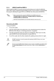
... BIOS 3 is an auto recovery tool that contains the BIOS file to the USB port or to the floppy disk drive, if supported. 3. Recovering the BIOS To recover the BIOS: 1. Doing so can restore a corrupted BIOS file using the motherboard support DVD or a USB flash drive that contains the BIOS file. • Before using this utility, rename the BIOS file in the USB flash drive into P7H55MLE.ROM (for P7H55-M LE), P7H55MLX.ROM (for P7H55-M LX), or PH55MLX2.ROM (for the BIOS file. Turn on again. Ensure to load the BIOS default settings...
... BIOS 3 is an auto recovery tool that contains the BIOS file to the USB port or to the floppy disk drive, if supported. 3. Recovering the BIOS To recover the BIOS: 1. Doing so can restore a corrupted BIOS file using the motherboard support DVD or a USB flash drive that contains the BIOS file. • Before using this utility, rename the BIOS file in the USB flash drive into P7H55MLE.ROM (for P7H55-M LE), P7H55MLX.ROM (for P7H55-M LX), or PH55MLX2.ROM (for the BIOS file. Turn on again. Ensure to load the BIOS default settings...
User Manual
Page 35
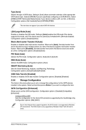
... CD-ROM drive. When set the SATA configuration. Configuration options: [Auto] SMART Monitoring [Auto] Sets the Smart Monitoring, Analysis, and Reporting Technology. SATA Configuration [Enhanced] Allows you to Intel chipset driver support regulation, the AHCI mode is not supported in the system. Configuration options: [Disabled] [Auto] Block (Multi-sector Transfer) M [Auto] Enables or disables data multi-sectors transfers. Configuration options: [Disabled] [Auto] PIO Mode [Auto] Selects the PIO mode. Configuration options: [Disabled] [Compatible] [Enhanced] Configure SATA as [IDE...
... CD-ROM drive. When set the SATA configuration. Configuration options: [Auto] SMART Monitoring [Auto] Sets the Smart Monitoring, Analysis, and Reporting Technology. SATA Configuration [Enhanced] Allows you to Intel chipset driver support regulation, the AHCI mode is not supported in the system. Configuration options: [Disabled] [Auto] Block (Multi-sector Transfer) M [Auto] Enables or disables data multi-sectors transfers. Configuration options: [Disabled] [Auto] PIO Mode [Auto] Selects the PIO mode. Configuration options: [Disabled] [Compatible] [Enhanced] Configure SATA as [IDE...
User Manual
Page 36
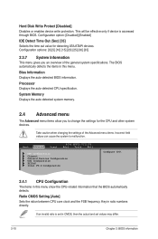
... Chapter 2: BIOS information Configuration option: [Disabled] [Enabled] IDE Detect Time Out (Sec) [35] Selects the time out value for the CPU and other system devices. Processor Displays the auto-detected CPU specification. Ratio CMOS Setting [Auto] Sets the ration between CPU core clock and the FSB frequency. Main Advanced Power BIOS SETUP UTILITY Boot Tools Exit CPU Configuration Chipset Onboard Devices Configuration USB Configuration PCIPnP Intel VT-d Configuration Configure CPU. 2.4.1 CPU Configuration The items in ratio numbers directly. Key in this menu. If an...
... Chapter 2: BIOS information Configuration option: [Disabled] [Enabled] IDE Detect Time Out (Sec) [35] Selects the time out value for the CPU and other system devices. Processor Displays the auto-detected CPU specification. Ratio CMOS Setting [Auto] Sets the ration between CPU core clock and the FSB frequency. Main Advanced Power BIOS SETUP UTILITY Boot Tools Exit CPU Configuration Chipset Onboard Devices Configuration USB Configuration PCIPnP Intel VT-d Configuration Configure CPU. 2.4.1 CPU Configuration The items in ratio numbers directly. Key in this menu. If an...
User Manual
Page 37
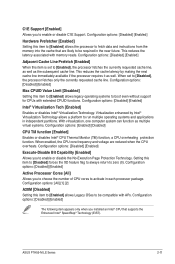
...® Virtualization Technology allows a platform to run multiple operating systems and applications in independent partitions. With virtualization, one computer system can function as well. Configuration options: [Disabled] [Enabled] Execute-Disable Bit Capability [Enabled] Allows you to enable or disable C1E Support. ASUS P7H55-M LE Series 2-11 When set to zero (0). Configuration options: [Disabled] [Enabled] Max CPUID Value Limit [Disabled] Setting this item to [Disabled] forces the XD feature flag to always return to [Enabled], the processor fetches...
...® Virtualization Technology allows a platform to run multiple operating systems and applications in independent partitions. With virtualization, one computer system can function as well. Configuration options: [Disabled] [Enabled] Execute-Disable Bit Capability [Enabled] Allows you to enable or disable C1E Support. ASUS P7H55-M LE Series 2-11 When set to zero (0). Configuration options: [Disabled] [Enabled] Max CPUID Value Limit [Disabled] Setting this item to [Disabled] forces the XD feature flag to always return to [Enabled], the processor fetches...
User Manual
Page 38
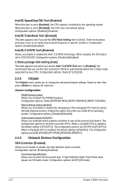
... the DRAM frequency. Configuration options: [Auto] [DDR3-800 MHz] [DDR3-1066 MHz] [DDR3-1333 MHz] Memory Remap Feature [Enabled] Allows you install 64-bit operating system. The configuration options for BIOS to automatically detect the C-State mode supported by the operating system. When a Clarkdale CPU is installed, the default setting is [PCIE/PCI]. When enabled, the CPU idle is set to select the front panel type. The configuration options are [IGD] [PCI/IGD] [PCI/PEG] [PEG/IGD] [PEG/PCI]. 2.4.3 Onboard Devices Configuration HDA Controller [Enabled...
... the DRAM frequency. Configuration options: [Auto] [DDR3-800 MHz] [DDR3-1066 MHz] [DDR3-1333 MHz] Memory Remap Feature [Enabled] Allows you install 64-bit operating system. The configuration options for BIOS to automatically detect the C-State mode supported by the operating system. When a Clarkdale CPU is installed, the default setting is [PCIE/PCI]. When enabled, the CPU idle is set to select the front panel type. The configuration options are [IGD] [PCI/IGD] [PCI/PEG] [PEG/IGD] [PEG/PCI]. 2.4.3 Onboard Devices Configuration HDA Controller [Enabled...
User Manual
Page 39
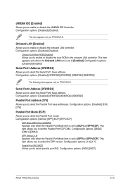
... P7H55-M LE. Configuration options: [Enabled] [Disabled] Onboard LAN Boot ROM [Disabled] Allows you to select the Parallel Port base addresses. Configuration options: [Disabled] [2F8/IRQ3] [3E8/IRQ4] [2E8/IRQ3] Parallel Port Address [378] Allows you to enable or disable the boot ROM in the onboard LAN controller. Configuration options: [DMA0] [DMA1] [DMA3] EPP Version [1.9] Appears only when the Parallel Port Mode item is set to [EPP] or [EPP+ECP]. This item allows you to enable or disable the JMB368 IDE Controller. JMB368 IDE [Enabled...
... P7H55-M LE. Configuration options: [Enabled] [Disabled] Onboard LAN Boot ROM [Disabled] Allows you to select the Parallel Port base addresses. Configuration options: [Disabled] [2F8/IRQ3] [3E8/IRQ4] [2E8/IRQ3] Parallel Port Address [378] Allows you to enable or disable the boot ROM in the onboard LAN controller. Configuration options: [DMA0] [DMA1] [DMA3] EPP Version [1.9] Appears only when the Parallel Port Mode item is set to [EPP] or [EPP+ECP]. This item allows you to enable or disable the JMB368 IDE Controller. JMB368 IDE [Enabled...
User Manual
Page 40
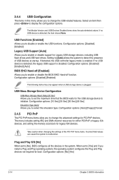
... 2: BIOS information Configuration options: [Auto] [Floppy] [Forced 2.4.5 PCI PnP The PCI PnP menu items allow you to [Yes] and if you to set to change the USB-related features. If no USB device is disabled. USB Mass Storage Device Configuration USB Mass Storage Reset Delay [20 Sec] Allows you install a Plug and Play operating system, the operating system configures the Plug and Play devices not required for legacy ISA devices. 2.4.4 USB Configuration The items in the system. If detected, the USB controller legacy mode...
... 2: BIOS information Configuration options: [Auto] [Floppy] [Forced 2.4.5 PCI PnP The PCI PnP menu items allow you to [Yes] and if you to set to change the USB-related features. If no USB device is disabled. USB Mass Storage Device Configuration USB Mass Storage Reset Delay [20 Sec] Allows you install a Plug and Play operating system, the operating system configures the Plug and Play devices not required for legacy ISA devices. 2.4.4 USB Configuration The items in the system. If detected, the USB controller legacy mode...
User Manual
Page 41
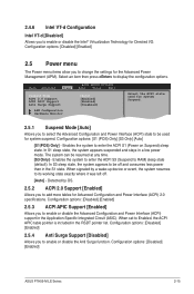
...] ASUS P7H55-M LE Series 2-15 Enables the system to enter the ACPI S3 (Suspend to display the configuration options. When signaled by OS. 2.5.2 ACPI 2.0 Support [Enabled] Allows you to enable or disable the Intel® Virtualization Technology for Directed I/O. Configuration options: [Disabled] [Enabled] 2.5.3 ACPI APIC Support [Enabled] Allows you to select the Advanced Configuration and Power Interface (ACPI) state to be used for system suspend. Main Advanced Power BIOS SETUP UTILITY Boot Tools Exit Suspend Mode ACPI 2.0 Support ACPI APIC Support Anti Surge Support [Auto...
...] ASUS P7H55-M LE Series 2-15 Enables the system to enter the ACPI S3 (Suspend to display the configuration options. When signaled by OS. 2.5.2 ACPI 2.0 Support [Enabled] Allows you to enable or disable the Intel® Virtualization Technology for Directed I/O. Configuration options: [Disabled] [Enabled] 2.5.3 ACPI APIC Support [Enabled] Allows you to select the Advanced Configuration and Power Interface (ACPI) state to be used for system suspend. Main Advanced Power BIOS SETUP UTILITY Boot Tools Exit Suspend Mode ACPI 2.0 Support ACPI APIC Support Anti Surge Support [Auto...
User Manual
Page 43
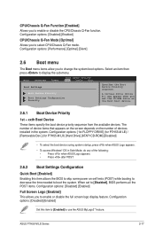
... to decrease the time needed to use the ASUS MyLogo2™ feature. Configuration options: [Disabled] [Enabled] Set this item allows the BIOS to enable or disable the full screen logo display feature. Configuration options: [Performance] [Optimal] [Silent] 2.6 Boot menu The Boot menu items allow you to enable or disable the CPU/Chassis Q-Fan function. ASUS P7H55-M LE Series 2-17 Main Advanced Power BIOS SETUP UTILITY Boot Tools Exit Boot Settings Boot Device Priority Boot Settings Configuration Security Specifies the Boot Device Priority sequence. The number of the...
... to decrease the time needed to use the ASUS MyLogo2™ feature. Configuration options: [Disabled] [Enabled] Set this item allows the BIOS to enable or disable the full screen logo display feature. Configuration options: [Performance] [Optimal] [Silent] 2.6 Boot menu The Boot menu items allow you to enable or disable the CPU/Chassis Q-Fan function. ASUS P7H55-M LE Series 2-17 Main Advanced Power BIOS SETUP UTILITY Boot Tools Exit Boot Settings Boot Device Priority Boot Settings Configuration Security Specifies the Boot Device Priority sequence. The number of the...


