
User Manual
Page 1
P7F-M WS Motherboard
P7F-M WS Motherboard

User Manual
Page 3
Contents Notices...vii Safety information viii About this guide ix Typography x P7F-M WS specifications summary xi Chapter 1: Product introduction 1.1 Welcome 1-3 1.2 Package contents 1-3 1.3 Serial number label 1-4 1.4 Special features 1-4 1.4.1 Product highlights 1-4 1.4.2 Innovative ASUS features 1-6 Chapter 2: Hardware information 2.1 Before you proceed 2-3 2.2 Motherboard overview 2-4 2.2.1 Placement direction 2-4 2.2.2 Screw holes 2-4 2.2.3 Motherboard layout 2-5 2.2.4 Layout contents 2-6 2.3 Central Processing Unit (CPU 2-8 2.3.1 Installing the CPU...
Contents Notices...vii Safety information viii About this guide ix Typography x P7F-M WS specifications summary xi Chapter 1: Product introduction 1.1 Welcome 1-3 1.2 Package contents 1-3 1.3 Serial number label 1-4 1.4 Special features 1-4 1.4.1 Product highlights 1-4 1.4.2 Innovative ASUS features 1-6 Chapter 2: Hardware information 2.1 Before you proceed 2-3 2.2 Motherboard overview 2-4 2.2.1 Placement direction 2-4 2.2.2 Screw holes 2-4 2.2.3 Motherboard layout 2-5 2.2.4 Layout contents 2-6 2.3 Central Processing Unit (CPU 2-8 2.3.1 Installing the CPU...

User Manual
Page 15
...list below. 1.2 Package contents Check your motherboard package for buying an ASUS® P7F-M WS motherboard! Before you for the following items. Standard Gift Box Pack P7F-M WS Cables SATA data cable 6 Accessories IO shield 1 Card ASUS MIO audio card 1 Application CD Support CD.... 1 pcs per carton Standard Bulk Pack P7F-M WS -1 -1 1 10 pcs per carton Items ASUS MIO audio card Description Discrete 8 channel audio card provides the clearest high quality sounds If any of ASUS quality motherboards! ASUS P7F-M WS 1-3 The motherboard delivers a host of new features and latest...
...list below. 1.2 Package contents Check your motherboard package for buying an ASUS® P7F-M WS motherboard! Before you for the following items. Standard Gift Box Pack P7F-M WS Cables SATA data cable 6 Accessories IO shield 1 Card ASUS MIO audio card 1 Application CD Support CD.... 1 pcs per carton Standard Bulk Pack P7F-M WS -1 -1 1 10 pcs per carton Items ASUS MIO audio card Description Discrete 8 channel audio card provides the clearest high quality sounds If any of ASUS quality motherboards! ASUS P7F-M WS 1-3 The motherboard delivers a host of new features and latest...

User Manual
Page 16
...great graphics performance. The Intel® EM64T feature allows your problems. P7F-M WS xxS1xxxxxxxxx Made in China 合格 1.4 Special features 1.4.1 Product highlights Intel® LGA1156 Xeon 3400 Processor Ready This motherboard supports the latest Intel® Xeon 3400 processors in the world.... 1.3 Serial number label Before requesting support from the ASUS Technical Support team, you must take note of the most powerful ...
...great graphics performance. The Intel® EM64T feature allows your problems. P7F-M WS xxS1xxxxxxxxx Made in China 合格 1.4 Special features 1.4.1 Product highlights Intel® LGA1156 Xeon 3400 Processor Ready This motherboard supports the latest Intel® Xeon 3400 processors in the world.... 1.3 Serial number label Before requesting support from the ASUS Technical Support team, you must take note of the most powerful ...

User Manual
Page 17
... more flexible cables with USB 1.1. USB 2.0 technology The motherboard implements the Universal Serial Bus (USB) 2.0 specification, dramatically increasing the connection speed from 1.8 V for DDR2 to just 1.5V for your networking needs. ASUS P7F-M WS 1-5 This voltage reduction limits the power consumption and ...heat generation of DDR3 which provide a total solution for DDR3. Serial ATA II technology The motherboard supports the Serial ATA II 3 Gb/s technology through...
... more flexible cables with USB 1.1. USB 2.0 technology The motherboard implements the Universal Serial Bus (USB) 2.0 specification, dramatically increasing the connection speed from 1.8 V for DDR2 to just 1.5V for your networking needs. ASUS P7F-M WS 1-5 This voltage reduction limits the power consumption and ...heat generation of DDR3 which provide a total solution for DDR3. Serial ATA II technology The motherboard supports the Serial ATA II 3 Gb/s technology through...

User Manual
Page 20
Diagnosis card installation (optional 2-29 ASUS P7F-M WS Chapter summary 2 2.1 Before you proceed 2-3 2.2 Motherboard overview 2-4 2.3 Central Processing Unit (CPU 2-8 2.4 System memory 2-13 2.5 Expansion slots 2-15 2.6 Jumpers 2-19 2.7 Connectors 2-22 2.8 G.P.
Diagnosis card installation (optional 2-29 ASUS P7F-M WS Chapter summary 2 2.1 Before you proceed 2-3 2.2 Motherboard overview 2-4 2.3 Central Processing Unit (CPU 2-8 2.4 System memory 2-13 2.5 Expansion slots 2-15 2.6 Jumpers 2-19 2.7 Connectors 2-22 2.8 G.P.
User Manual
Page 21
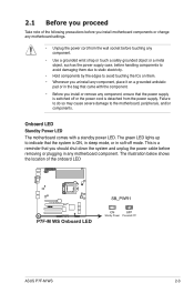
... on a grounded antistatic pad or in any motherboard component. Failure to do so may cause severe...to the motherboard, peripherals, and/or components. Onboard LED Standby Power LED The motherboard comes ...with the component. • Before you should shut down the system and unplug the power cable before removing or plugging in the bag that came with a standby power LED. The illustration below shows the location of the following precautions before you install motherboard... components or change any motherboard settings. • Unplug the...
... on a grounded antistatic pad or in any motherboard component. Failure to do so may cause severe...to the motherboard, peripherals, and/or components. Onboard LED Standby Power LED The motherboard comes ...with the component. • Before you should shut down the system and unplug the power cable before removing or plugging in the bag that came with a standby power LED. The illustration below shows the location of the following precautions before you install motherboard... components or change any motherboard settings. • Unplug the...

User Manual
Page 23
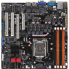
2.2.3 Motherboard layout ASUS P7F-M WS 2-5
2.2.3 Motherboard layout ASUS P7F-M WS 2-5

User Manual
Page 29
.... The LGA1156 socket is closest to the CPU fan connector. If you purchased a separate CPU heatsink and fan assembly, ensure that you have installed the motherboard to the chassis before you install the CPU fan and heatsink assembly. A B A A B 1 B A 1 Orient the heatsink and fan assembly such ...install. • Use an LGA1156-compatible CPU heatsink and fan assembly only. To install the CPU heatsink and fan: 1. ASUS P7F-M WS 2-11 Place the heatsink on the motherboard. If you buy a CPU separately, ensure that you buy a boxed Intel® processor, the package includes the CPU fan...
.... The LGA1156 socket is closest to the CPU fan connector. If you purchased a separate CPU heatsink and fan assembly, ensure that you have installed the motherboard to the chassis before you install the CPU fan and heatsink assembly. A B A A B 1 B A 1 Orient the heatsink and fan assembly such ...install. • Use an LGA1156-compatible CPU heatsink and fan assembly only. To install the CPU heatsink and fan: 1. ASUS P7F-M WS 2-11 Place the heatsink on the motherboard. If you buy a CPU separately, ensure that you buy a boxed Intel® processor, the package includes the CPU fan...

User Manual
Page 31
DDR3 modules are not supported ASUS P7F-M WS 2-13 RDIMM* DIMM Slot DIMM Populated DIMM Type Speed Rank per DIMM ...(DDR3) Dual Inline Memory Modules (DIMM) sockets. DO NOT combine RDIMM and UDIMM. • The motherboard supports x8 DRAM Only and x4 & x16 DRAM are developed for better performance with the same CAS latency. 2.4 System memory 2.4.1 Overview ...The motherboard comes with ECC/Non-ECC DDR3 DIMMs into the DIMM sockets using the memory configurations in this section...
DDR3 modules are not supported ASUS P7F-M WS 2-13 RDIMM* DIMM Slot DIMM Populated DIMM Type Speed Rank per DIMM ...(DDR3) Dual Inline Memory Modules (DIMM) sockets. DO NOT combine RDIMM and UDIMM. • The motherboard supports x8 DRAM Only and x4 & x16 DRAM are developed for better performance with the same CAS latency. 2.4 System memory 2.4.1 Overview ...The motherboard comes with ECC/Non-ECC DDR3 DIMMs into the DIMM sockets using the memory configurations in this section...

User Manual
Page 33
... the slot that the cards do so may need IRQ assignments. Secure the card to the chassis with the screw you physical injury and damage motherboard components. 2.5.1 Installing an expansion card To install an expansion card: 1. Replace the system cover. 2.5.2 Configuring an expansion card After installing the expansion card, configure the... slot and press firmly until the card is already installed in a chassis). 3. Keep the screw for the card. 2. Remove the system unit cover (if your motherboard is completely seated on the system and change the necessary BIOS settings, if any...
... the slot that the cards do so may need IRQ assignments. Secure the card to the chassis with the screw you physical injury and damage motherboard components. 2.5.1 Installing an expansion card To install an expansion card: 1. Replace the system cover. 2.5.2 Configuring an expansion card After installing the expansion card, configure the... slot and press firmly until the card is already installed in a chassis). 3. Keep the screw for the card. 2. Remove the system unit cover (if your motherboard is completely seated on the system and change the necessary BIOS settings, if any...
User Manual
Page 43
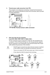
Connect the thermal sensor cable to this connector and place the other end to the device, which you want to the fan connectors. ASUS P7F-M WS 2-25 CPU, front and rear fan connectors (4-pin CPU_FAN1, FRNT_FAN1-3, REAR_FAN1) The fan connectors support cooling fans of 350 mA-740 mA (8.88 W max... are not jumpers! Connect the fan cables to the fan connectors on the fan connectors! • All fans feature the ASUS Fan Speed Control technology. DO NOT place jumper caps on the motherboard, ensuring that the black wire of each cable matches the ground pin of 1.75 A-3.7 A (44.4 W max.) at +12V. ...
Connect the thermal sensor cable to this connector and place the other end to the device, which you want to the fan connectors. ASUS P7F-M WS 2-25 CPU, front and rear fan connectors (4-pin CPU_FAN1, FRNT_FAN1-3, REAR_FAN1) The fan connectors support cooling fans of 350 mA-740 mA (8.88 W max... are not jumpers! Connect the fan cables to the fan connectors on the fan connectors! • All fans feature the ASUS Fan Speed Control technology. DO NOT place jumper caps on the motherboard, ensuring that the black wire of each cable matches the ground pin of 1.75 A-3.7 A (44.4 W max.) at +12V. ...

User Manual
Page 47
Diagnosis card installation (optional) 2.8.1 G.P. Reset Button. Press to avoid electrical shock hazard. 1. ASUS P7F-M WS 2-29 Locate the TPM connector (20-1 pin TPM) on the connector completely. Diagnosis card Ensure to turn off the power supply unit before installing ... 0 and 1 Power Switch. Press to the PCI slots, align the card connector with the TPM connector and press firmly until the card sits on the motherboard. 2. 2.8 G.P.
Diagnosis card installation (optional) 2.8.1 G.P. Reset Button. Press to avoid electrical shock hazard. 1. ASUS P7F-M WS 2-29 Locate the TPM connector (20-1 pin TPM) on the connector completely. Diagnosis card Ensure to turn off the power supply unit before installing ... 0 and 1 Power Switch. Press to the PCI slots, align the card connector with the TPM connector and press firmly until the card sits on the motherboard. 2. 2.8 G.P.

User Manual
Page 55
...End] Move [Tab] Switch [B] Backup [V] Drive Info [Esc] Exit ASUS P7F-M WS 4-3 4.1 Managing and updating your BIOS The following utilities allow you need to restore the BIOS in the future. Save a copy of the original motherboard BIOS file to a bootable USB flash disk drive in DOS mode using... the BUPDATER utility. 4.1.1 ASUS EZ Flash 2 utility The ASUS EZ Flash 2 feature allows you start using a USB flash disk.) 2. BUPDATER utility...
...End] Move [Tab] Switch [B] Backup [V] Drive Info [Esc] Exit ASUS P7F-M WS 4-3 4.1 Managing and updating your BIOS The following utilities allow you need to restore the BIOS in the future. Save a copy of the original motherboard BIOS file to a bootable USB flash disk drive in DOS mode using... the BUPDATER utility. 4.1.1 ASUS EZ Flash 2 utility The ASUS EZ Flash 2 feature allows you start using a USB flash disk.) 2. BUPDATER utility...

User Manual
Page 59
Do this motherboard. ASUS P7F-M WS 4-7 If you scroll through the various sub-menus and make it as possible. Being a menu-driven program, it lets you wish to enter Setup ... how to configure your system using the navigation keys. • The default BIOS settings for this motherboard apply for most conditions to "Run Setup." The Firmware chip on your screen. • Visit the ASUS website (www.asus.com) to make your selections from the available options using this program. The Setup program is...
Do this motherboard. ASUS P7F-M WS 4-7 If you scroll through the various sub-menus and make it as possible. Being a menu-driven program, it lets you wish to enter Setup ... how to configure your system using the navigation keys. • The default BIOS settings for this motherboard apply for most conditions to "Run Setup." The Firmware chip on your screen. • Visit the ASUS website (www.asus.com) to make your selections from the available options using this program. The Setup program is...

User Manual
Page 83
... to configure the ASUS Smart Fan feature that smartly adjusts the fan speeds for more efficient system operation. CPU/MB/TR1 Temperature [xxxºC/xxxºF] The onboard hardware monitor automatically detects and displays the motherboard component and CPU ... fans, front fans, and rear fans in rotations per minute (RPM). Fan Speed Control [Generic Mode] Allows you to the motherboard, the field shows [N/A]. CPU Fan1; Configuration options: [Full Speed Mode] [High Density Mode] [Generic Mode] [Whisper Mode...Ignored] if you do not wish to detect this item. ASUS P7F-M WS 4-31
... to configure the ASUS Smart Fan feature that smartly adjusts the fan speeds for more efficient system operation. CPU/MB/TR1 Temperature [xxxºC/xxxºF] The onboard hardware monitor automatically detects and displays the motherboard component and CPU ... fans, front fans, and rear fans in rotations per minute (RPM). Fan Speed Control [Generic Mode] Allows you to the motherboard, the field shows [N/A]. CPU Fan1; Configuration options: [Full Speed Mode] [High Density Mode] [Generic Mode] [Whisper Mode...Ignored] if you do not wish to detect this item. ASUS P7F-M WS 4-31

User Manual
Page 93
...without parity (redundancy data) having to a second drive. Refer to section 6.1 Creating a RAID driver disk for this setup. ASUS P7F-M WS 5-3 5.1 Setting up RAID The motherboard comes with the total capacity over 2TB can only be set as a data disk only. • If you want to install... a Windows® operating system to create a RAID driver disk and load the RAID driver during OS installation. The motherboard supports the following RAID configurations: RAID 0, RAID 1, RAID 10 and RAID 5. • You must be of RAID 5 configuration include better HDD ...
...without parity (redundancy data) having to a second drive. Refer to section 6.1 Creating a RAID driver disk for this setup. ASUS P7F-M WS 5-3 5.1 Setting up RAID The motherboard comes with the total capacity over 2TB can only be set as a data disk only. • If you want to install... a Windows® operating system to create a RAID driver disk and load the RAID driver during OS installation. The motherboard supports the following RAID configurations: RAID 0, RAID 1, RAID 10 and RAID 5. • You must be of RAID 5 configuration include better HDD ...
User Manual
Page 107
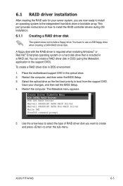
... drive or bootable array. You can create a RAID driver disk in DOS (using the Makedisk application in a RAID set. Restart the computer. Place the motherboard support DVD in DOS environment 1. You have to boot from the support DVD. Select the optical drive as the first boot priority to use a USB... to install the RAID controller drivers during OS installation. 6.1.1 Creating a RAID driver disk The system does not include a floppy drive. The Makedisk menu appears. ASUS P7F-M WS 6-3 This part provides instructions on a hard disk drive that is included in the support DVD).
... drive or bootable array. You can create a RAID driver disk in DOS (using the Makedisk application in a RAID set. Restart the computer. Place the motherboard support DVD in DOS environment 1. You have to boot from the support DVD. Select the optical drive as the first boot priority to use a USB... to install the RAID controller drivers during OS installation. 6.1.1 Creating a RAID driver disk The system does not include a floppy drive. The Makedisk menu appears. ASUS P7F-M WS 6-3 This part provides instructions on a hard disk drive that is included in the support DVD).

User Manual
Page 117
ASUS P7F-M WS 6-13 The screen display and driver options vary under different operating system versions. Visit the ASUS website (www.asus.com) for updates. 6.4.1 Running the support DVD Place the support DVD to activate the devices. Install the necessary drivers to ...support DVD to change at any time without notice. Double-click the ASSETUP.EXE to avail all motherboard features. 6.4 Management applications and utilities installation The support DVD that came with the motherboard package contains the drivers, management applications, and utilities that you can install to run the DVD....
ASUS P7F-M WS 6-13 The screen display and driver options vary under different operating system versions. Visit the ASUS website (www.asus.com) for updates. 6.4.1 Running the support DVD Place the support DVD to activate the devices. Install the necessary drivers to ...support DVD to change at any time without notice. Double-click the ASSETUP.EXE to avail all motherboard features. 6.4 Management applications and utilities installation The support DVD that came with the motherboard package contains the drivers, management applications, and utilities that you can install to run the DVD....


