
Motherboard Installation Guide
Page 1
P5VDC-X Motherboard
P5VDC-X Motherboard

Motherboard Installation Guide
Page 3
Contents Notices vi Safety information vii About this guide viii P5VDC-X specifications summary x Chapter 1: Product introduction 1.1 Welcome 1-2 1.2 Package contents 1-2 1.3 Special features 1-2 1.3.1 Product highlights 1-2 1.3.2 Innovative ASUS features 1-4 1.4 Before you proceed 1-5 1.5 Motherboard overview 1-6 1.5.1 Placement direction 1-6 1.5.2 Screw holes 1-6 1.5.3 Motherboard layout 1-7 1.6 Central Processing Unit (CPU 1-8 1.6.1 Installling the CPU 1-8 1.6.2 Installling the CPU heatsink and fan 1-11 1.6.3 Uninstalling the...
Contents Notices vi Safety information vii About this guide viii P5VDC-X specifications summary x Chapter 1: Product introduction 1.1 Welcome 1-2 1.2 Package contents 1-2 1.3 Special features 1-2 1.3.1 Product highlights 1-2 1.3.2 Innovative ASUS features 1-4 1.4 Before you proceed 1-5 1.5 Motherboard overview 1-6 1.5.1 Placement direction 1-6 1.5.2 Screw holes 1-6 1.5.3 Motherboard layout 1-7 1.6 Central Processing Unit (CPU 1-8 1.6.1 Installling the CPU 1-8 1.6.2 Installling the CPU heatsink and fan 1-11 1.6.3 Uninstalling the...

Motherboard Installation Guide
Page 7
...or removing devices to the correct voltage in your area. Contact a qualified service technician or your retailer. Operation safety • Before installing the motherboard and adding devices on a stable surface. • If you are unplugged. • Seek professional assistance before using an adapter or extension ...cord. If you add a device. • Before connecting or removing signal cables from the motherboard, ensure that your power supply is broken, do not try to fix it , carefully read all the manuals that the power cables for...
...or removing devices to the correct voltage in your area. Contact a qualified service technician or your retailer. Operation safety • Before installing the motherboard and adding devices on a stable surface. • If you are unplugged. • Seek professional assistance before using an adapter or extension ...cord. If you add a device. • Before connecting or removing signal cables from the motherboard, ensure that your power supply is broken, do not try to fix it , carefully read all the manuals that the power cables for...

Motherboard Installation Guide
Page 8
... following parts: • Chapter 1: Product introduction This chapter describes the features of the support CD that comes with the motherboard package. Where to find more information Refer to perform when installing system components. viii Detailed descriptions of the BIOS parameters are... not part of the jumpers and connectors on ASUS hardware and software products. ASUS websites The ASUS website provides updated information on the motherboard. • Chapter 2: BIOS setup This chapter tells how to the ASUS contact information. 2. How this guide This user guide ...
... following parts: • Chapter 1: Product introduction This chapter describes the features of the support CD that comes with the motherboard package. Where to find more information Refer to perform when installing system components. viii Detailed descriptions of the BIOS parameters are... not part of the jumpers and connectors on ASUS hardware and software products. ASUS websites The ASUS website provides updated information on the motherboard. • Chapter 2: BIOS setup This chapter tells how to the ASUS contact information. 2. How this guide This user guide ...
Motherboard Installation Guide
Page 13
This chapter describes the motherboard features and the new technologies it supports. 1Product introduction ASUS P5VDC-X 1-1
This chapter describes the motherboard features and the new technologies it supports. 1Product introduction ASUS P5VDC-X 1-1
Motherboard Installation Guide
Page 14
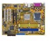
...® 4 processor in your motherboard package for the following items. Motherboard ASUS P5VDC-X motherboard Cables 1 x Serial ATA cable 1 x Serial ATA power cable 1 x Ultra DMA 133/100/66 cable 1 x Floppy disk drive cable Accessories I/O shield Application CD ASUS motherboard support CD Documentation User guide If any of ASUS quality motherboards! Thank you start installing the motherboard, and hardware devices on the...
...® 4 processor in your motherboard package for the following items. Motherboard ASUS P5VDC-X motherboard Cables 1 x Serial ATA cable 1 x Serial ATA power cable 1 x Ultra DMA 133/100/66 cable 1 x Floppy disk drive cable Accessories I/O shield Application CD ASUS motherboard support CD Documentation User guide If any of ASUS quality motherboards! Thank you start installing the motherboard, and hardware devices on the...
Motherboard Installation Guide
Page 15
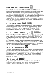
... required bandwidth for two SATA connectors. Dual Channel DDR and DDRII support Employing the Double Data Rate (DDR) memory technology, the motherboard supports up to 2GB of 533MHz, DDR2 memory provides bandwidth up to 4.3GB/ s. Doubled by the dual-channel architecture, the ..., and low power consumption. Serial ATA RAID technology Serial ATA is faster than current Parallel ATA, while providing 100% software compatibility. ASUS P5VDC-X 1-3 Allows you to your network or broadband connection with copper interconnect. See page 1-15 for today and tomorrow. See page 1-22...
... required bandwidth for two SATA connectors. Dual Channel DDR and DDRII support Employing the Double Data Rate (DDR) memory technology, the motherboard supports up to 2GB of 533MHz, DDR2 memory provides bandwidth up to 4.3GB/ s. Doubled by the dual-channel architecture, the ..., and low power consumption. Serial ATA RAID technology Serial ATA is faster than current Parallel ATA, while providing 100% software compatibility. ASUS P5VDC-X 1-3 Allows you to your network or broadband connection with copper interconnect. See page 1-15 for today and tomorrow. See page 1-22...
Motherboard Installation Guide
Page 16
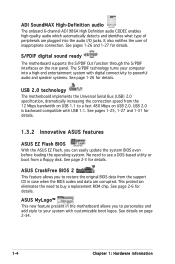
... into the audio I/O jacks. S/PDIF digital sound ready The motherboard supports the S/PDIF Out function through the S/PDIF interfaces on USB 2.0. See pages 1-25, 1-27 and 1-31 for details. 1.3.2 Innovative ASUS features ASUS EZ Flash BIOS With the ASUS EZ Flash, you to personalize and add style to use a... DOS-based utility or boot from the support CD in the motherboard allows you can easily update the system BIOS even before loading ...
... into the audio I/O jacks. S/PDIF digital sound ready The motherboard supports the S/PDIF Out function through the S/PDIF interfaces on USB 2.0. See pages 1-25, 1-27 and 1-31 for details. 1.3.2 Innovative ASUS features ASUS EZ Flash BIOS With the ASUS EZ Flash, you to personalize and add style to use a... DOS-based utility or boot from the support CD in the motherboard allows you can easily update the system BIOS even before loading ...
Motherboard Installation Guide
Page 17
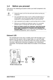
...to static electricity. • Hold components by the edges to indicate that the system is ON, in sleep mode, or in any motherboard component. The illustration below shows the location of the following precautions before you install components into the system. • Unplug the power...Line In Center:Line Out Below:Mic In P5VDC-X R P5VDC-X Onboard LED SB_PWR ON Standby Power OFF Powered Off ASUS P5VDC-X 1-5 This is switched off mode. 1.4 Before you proceed Take note of the onboard LED. Failure to do so may cause severe damage to the motherboard, peripherals, and/or components.
...to static electricity. • Hold components by the edges to indicate that the system is ON, in sleep mode, or in any motherboard component. The illustration below shows the location of the following precautions before you install components into the system. • Unplug the power...Line In Center:Line Out Below:Mic In P5VDC-X R P5VDC-X Onboard LED SB_PWR ON Standby Power OFF Powered Off ASUS P5VDC-X 1-5 This is switched off mode. 1.4 Before you proceed Take note of the onboard LED. Failure to do so may cause severe damage to the motherboard, peripherals, and/or components.

Motherboard Installation Guide
Page 18
...chassis Top:Line In Center:Line Out Below:Mic In P5VDC-X R 1-6 Chapter 1: Hardware information Doing so can cause you physical injury and damage motherboard components. 1.5.1 Placement direction When installing the motherboard, make sure that you install the motherboard, study the configuration of your chassis to... ensure that the motherboard fits into it into the holes indicated by circles to secure the motherboard to do so can damage the motherboard. Place this side towards the rear of the chassis as indicated in the image ...
...chassis Top:Line In Center:Line Out Below:Mic In P5VDC-X R 1-6 Chapter 1: Hardware information Doing so can cause you physical injury and damage motherboard components. 1.5.1 Placement direction When installing the motherboard, make sure that you install the motherboard, study the configuration of your chassis to... ensure that the motherboard fits into it into the holes indicated by circles to secure the motherboard to do so can damage the motherboard. Place this side towards the rear of the chassis as indicated in the image ...

Motherboard Installation Guide
Page 20
...P5VDC-X R P5VDC-X CPU Socket 775 Before installing the CPU, make sure that the socket box is facing towards you and the load lever is missing, or if you see any damage to the socket contacts resulting from incorrect CPU installation/removal, or misplacement/loss/incorrect removal of the motherboard..., make sure that the PnP cap is shipment/ transit-related. • Keep the cap after installing the motherboard. ASUS will shoulder the cost of repair only if the damage is on the ...
...P5VDC-X R P5VDC-X CPU Socket 775 Before installing the CPU, make sure that the socket box is facing towards you and the load lever is missing, or if you see any damage to the socket contacts resulting from incorrect CPU installation/removal, or misplacement/loss/incorrect removal of the motherboard..., make sure that the PnP cap is shipment/ transit-related. • Keep the cap after installing the motherboard. ASUS will shoulder the cost of repair only if the damage is on the ...
Motherboard Installation Guide
Page 22
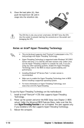
... Linux, use the Hyper-Threading Technology on Intel® Hyper-Threading Technology • This motherboard supports Intel® Pentium® 4 processor in BIOS before installing a supported operating system. • For more information on the socket and damaging the CPU. Under ...
... Linux, use the Hyper-Threading Technology on Intel® Hyper-Threading Technology • This motherboard supports Intel® Pentium® 4 processor in BIOS before installing a supported operating system. • For more information on the socket and damaging the CPU. Under ...
Motherboard Installation Guide
Page 23
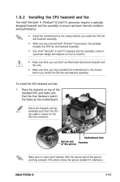
... of the groove Motherboard hole Fastener Make sure to orient each fastener with the narrow end of the installed CPU, and make sure that the four fasteners match the holes on top of the groove pointing outward. (The photo shows the groove shaded for emphasis.) ASUS P5VDC-X 1-11 To install... the CPU heatsink and fan: 1. Orient the heatsink and fan assembly such that you have installed the motherboard to the chassis before you install the CPU fan and heatsink assembly. • ...
... of the groove Motherboard hole Fastener Make sure to orient each fastener with the narrow end of the installed CPU, and make sure that the four fasteners match the holes on top of the groove pointing outward. (The photo shows the groove shaded for emphasis.) ASUS P5VDC-X 1-11 To install... the CPU heatsink and fan: 1. Orient the heatsink and fan assembly such that you have installed the motherboard to the chassis before you install the CPU fan and heatsink assembly. • ...

Motherboard Installation Guide
Page 24
A A B A B B A 3. 2. Hardware monitoring errors can occur if you fail to secure the heatsink and B fan assembly in a diagonal sequence to plug this connector. 1-12 Chapter 1: Hardware information Push down two fasteners at a time in place. Connect the CPU fan cable to connect the CPU fan connector! Top:Line In Center:Line Out Below:Mic In P5VDC-X R CPU_FAN GND CPU FAN PWR CPU FAN IN CPU FAN PWM P5VDC-X CPU FAN Connector Do not forget to the connector on the motherboard labeled CPU_FAN.
A A B A B B A 3. 2. Hardware monitoring errors can occur if you fail to secure the heatsink and B fan assembly in a diagonal sequence to plug this connector. 1-12 Chapter 1: Hardware information Push down two fasteners at a time in place. Connect the CPU fan cable to connect the CPU fan connector! Top:Line In Center:Line Out Below:Mic In P5VDC-X R CPU_FAN GND CPU FAN PWR CPU FAN IN CPU FAN PWM P5VDC-X CPU FAN Connector Do not forget to the connector on the motherboard labeled CPU_FAN.
Motherboard Installation Guide
Page 25
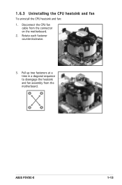
Rotate each fastener counterclockwise. 3. B A B B A ASUS P5VDC-X 1-13 1.6.3 Uninstalling the CPU heatsink and fan To uninstall the CPU heatsink and fan: 1. Pull up two fasteners at a time in a diagonal sequence to disengage the heatsink B and fan assembly from the connector on the motherboard. 2. Disconnect the CPU fan cable from the A A motherboard.
Rotate each fastener counterclockwise. 3. B A B B A ASUS P5VDC-X 1-13 1.6.3 Uninstalling the CPU heatsink and fan To uninstall the CPU heatsink and fan: 1. Pull up two fasteners at a time in a diagonal sequence to disengage the heatsink B and fan assembly from the connector on the motherboard. 2. Disconnect the CPU fan cable from the A A motherboard.

Motherboard Installation Guide
Page 26
Narrow end of the groove 1-14 Chapter 1: Hardware information Remove the heatsink and fan assembly from the motherboard. 5. When reset, each fastener clockwise to reset the orientation. Rotate each fastener should be oriented as shown, with the narrow groove directed outward. 4.
Narrow end of the groove 1-14 Chapter 1: Hardware information Remove the heatsink and fan assembly from the motherboard. 5. When reset, each fastener clockwise to reset the orientation. Rotate each fastener should be oriented as shown, with the narrow groove directed outward. 4.
Motherboard Installation Guide
Page 27
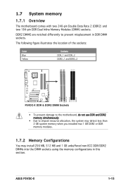
... Blue Yellow Sockets DDR_1 and DDR_2 DDR2_1 and DDR2_2 Top:Line In Center:Line Out Below:Mic In P5VDC-X R DDR2_B1 DDR2_A1 DDR_B1 DDR_A1 P5VDC-X DDR & DDR2 DIMM Sockets • To prevent damage to the motherboard, do not use DDR and DDR2 memory simultaneously. • Due to prevent misplacement in this section. 1.7 System memory... MB, 512 MB and 1 GB unbuffered non-ECC DDR/DDR2 DIMMs into the DIMM sockets using the memory configurations in DDR DIMM sockets. ASUS P5VDC-X 1-15
... Blue Yellow Sockets DDR_1 and DDR_2 DDR2_1 and DDR2_2 Top:Line In Center:Line Out Below:Mic In P5VDC-X R DDR2_B1 DDR2_A1 DDR_B1 DDR_A1 P5VDC-X DDR & DDR2 DIMM Sockets • To prevent damage to the motherboard, do not use DDR and DDR2 memory simultaneously. • Due to prevent misplacement in this section. 1.7 System memory... MB, 512 MB and 1 GB unbuffered non-ECC DDR/DDR2 DIMMs into the DIMM sockets using the memory configurations in DDR DIMM sockets. ASUS P5VDC-X 1-15

Motherboard Installation Guide
Page 30
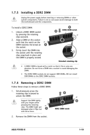
.... 1 1 DDR DIMM notch Support the DIMM lightly with your fingers when pressing the retaining clips. Firmly insert the DIMM into a socket to both the motherboard and the components. 1.
.... 1 1 DDR DIMM notch Support the DIMM lightly with your fingers when pressing the retaining clips. Firmly insert the DIMM into a socket to both the motherboard and the components. 1.
Motherboard Installation Guide
Page 31
... Follow these steps to remove a DDR2 DIMM. 1. The DIMM might get damaged when it fits in only one direction. ASUS P5VDC-X 1-19 Simultaneously press the retaining clips outward to both the motherboard and the components. Do not force a DIMM into the socket until the retaining clips snap back in place and the...
... Follow these steps to remove a DDR2 DIMM. 1. The DIMM might get damaged when it fits in only one direction. ASUS P5VDC-X 1-19 Simultaneously press the retaining clips outward to both the motherboard and the components. Do not force a DIMM into the socket until the retaining clips snap back in place and the...
Motherboard Installation Guide
Page 32
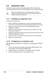
... install expansion cards. Remove the bracket opposite the slot that they support. 1.8 Expansion slots In the future, you may cause you physical injury and damage motherboard components. 1.8.1 Installing an expansion card To install an expansion card: 1. Before installing the expansion card, read the documentation that came with the screw you ... card, configure it and make the necessary hardware settings for information on the next page. 3. Remove the system unit cover (if your motherboard is completely seated on the system and change the necessary BIOS settings, if any.
... install expansion cards. Remove the bracket opposite the slot that they support. 1.8 Expansion slots In the future, you may cause you physical injury and damage motherboard components. 1.8.1 Installing an expansion card To install an expansion card: 1. Before installing the expansion card, read the documentation that came with the screw you ... card, configure it and make the necessary hardware settings for information on the next page. 3. Remove the system unit cover (if your motherboard is completely seated on the system and change the necessary BIOS settings, if any.


