
Motherboard Installation Guide
Page 3
... vii About this guide viii P5VDC-X specifications summary x Chapter 1: Product introduction 1.1 Welcome 1-2 1.2 Package contents 1-2 1.3 Special features 1-2 1.3.1 Product highlights 1-2 1.3.2 Innovative ASUS features 1-4 1.4 Before you proceed 1-5 1.5 Motherboard overview 1-6 1.5.1 Placement direction 1-6 1.5.2 Screw holes 1-6 1.5.3 Motherboard layout 1-7 1.6 Central Processing Unit (CPU 1-8 1.6.1 Installling the CPU 1-8 1.6.2 Installling the CPU heatsink and fan 1-11 1.6.3 Uninstalling the CPU heatsink and fan 1-13 1.7 System...
... vii About this guide viii P5VDC-X specifications summary x Chapter 1: Product introduction 1.1 Welcome 1-2 1.2 Package contents 1-2 1.3 Special features 1-2 1.3.1 Product highlights 1-2 1.3.2 Innovative ASUS features 1-4 1.4 Before you proceed 1-5 1.5 Motherboard overview 1-6 1.5.1 Placement direction 1-6 1.5.2 Screw holes 1-6 1.5.3 Motherboard layout 1-7 1.6 Central Processing Unit (CPU 1-8 1.6.1 Installling the CPU 1-8 1.6.2 Installling the CPU heatsink and fan 1-11 1.6.3 Uninstalling the CPU heatsink and fan 1-13 1.7 System...
Motherboard Installation Guide
Page 4
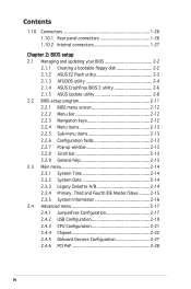
... 1-27 Chapter 2: BIOS setup 2.1 Managing and updating your BIOS 2-2 2.1.1 Creating a bootable floppy disk 2-2 2.1.2 ASUS EZ Flash utility 2-3 2.1.3 AFUDOS utility 2-4 2.1.4 ASUS CrashFree BIOS 2 utility 2-6 2.1.5 ASUS Update utility 2-8 2.2 BIOS setup program 2-11 2.2.1 BIOS menu screen 2-12 2.2.2 Menu bar 2-12 2.2.3 Navigation keys 2-12... 2-16 2.4 Advanced menu 2-17 2.4.1 JumperFree Configuration 2-17 2.4.2 USB Configuration 2-19 2.4.3 CPU Configuration 2-21 2.4.4 Chipset 2-22 2.4.5 Onboard Devices Configuration 2-27 2.4.6 PCI PnP 2-28 iv
... 1-27 Chapter 2: BIOS setup 2.1 Managing and updating your BIOS 2-2 2.1.1 Creating a bootable floppy disk 2-2 2.1.2 ASUS EZ Flash utility 2-3 2.1.3 AFUDOS utility 2-4 2.1.4 ASUS CrashFree BIOS 2 utility 2-6 2.1.5 ASUS Update utility 2-8 2.2 BIOS setup program 2-11 2.2.1 BIOS menu screen 2-12 2.2.2 Menu bar 2-12 2.2.3 Navigation keys 2-12... 2-16 2.4 Advanced menu 2-17 2.4.1 JumperFree Configuration 2-17 2.4.2 USB Configuration 2-19 2.4.3 CPU Configuration 2-21 2.4.4 Chipset 2-22 2.4.5 Onboard Devices Configuration 2-27 2.4.6 PCI PnP 2-28 iv
Motherboard Installation Guide
Page 11
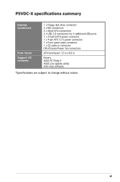
xi P5VDC-X specifications summary Internal connectors Form factor Support CD contents 1 x Floppy disk drive connector 2 x IDE connectors 2 x Serial ATA connectors 2 x USB 2.0 connectors for 4 additional USB ports 1 x 24-pin EATX power connector 1 x 4-pin ATX 12 V power connector 1 x Front panel audio connector 1 x CD audio-in connector CPU/Chassis/Power fan connectors ATX form factor: 12 in x 8.6 in Drivers ASUS PC Probe II ASUS Live Update utility Anti-virus software *Specifications are subject to change without notice.
xi P5VDC-X specifications summary Internal connectors Form factor Support CD contents 1 x Floppy disk drive connector 2 x IDE connectors 2 x Serial ATA connectors 2 x USB 2.0 connectors for 4 additional USB ports 1 x 24-pin EATX power connector 1 x 4-pin ATX 12 V power connector 1 x Front panel audio connector 1 x CD audio-in connector CPU/Chassis/Power fan connectors ATX form factor: 12 in x 8.6 in Drivers ASUS PC Probe II ASUS Live Update utility Anti-virus software *Specifications are subject to change without notice.
Motherboard Installation Guide
Page 14
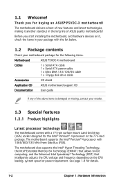
...any of ASUS quality motherboards! The motherboard also supports the Intel® Hyper-Threading Technology, the Intel® Extended Memory 64 Technology (EM64T) that allows 64-bit computing, and the Enhanced Intel Speedstep® Technology (EIST) that intelligently adjusts the CPU voltage ...Product highlights Latest processor technology The motherboard comes with 1066/800/533 MHz Front Side Bus (FSB). See page 1-8 for buying an ASUS® P5VDC-X motherboard! The motherboard delivers a host of new features and latest technologies, making it , check the items in the 775-land package...
...any of ASUS quality motherboards! The motherboard also supports the Intel® Hyper-Threading Technology, the Intel® Extended Memory 64 Technology (EM64T) that allows 64-bit computing, and the Enhanced Intel Speedstep® Technology (EIST) that intelligently adjusts the CPU voltage ...Product highlights Latest processor technology The motherboard comes with 1066/800/533 MHz Front Side Bus (FSB). See page 1-8 for buying an ASUS® P5VDC-X motherboard! The motherboard delivers a host of new features and latest technologies, making it , check the items in the 775-land package...
Motherboard Installation Guide
Page 15
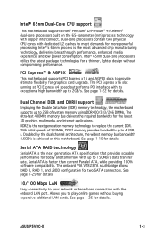
...allows RAID 0, RAID 1, and JBOD configuration for details. With up to provide ultimate flexibility for more powerful processing. ASUS P5VDC-X 1-3 See page 1-26 for details. Intel®ʼs 65nm process is the next generation ATA specification that provides scalable ... Data Rate (DDR) memory technology, the motherboard supports up to meet demands for graphics card upgrade. Intel® 65nm Dual-Core CPU support This motherboard supports Intel® Pentium® D/Pentium® 4/Celeron® dual-core processors built on this motherboard. Intel®...
...allows RAID 0, RAID 1, and JBOD configuration for details. With up to provide ultimate flexibility for more powerful processing. ASUS P5VDC-X 1-3 See page 1-26 for details. Intel®ʼs 65nm process is the next generation ATA specification that provides scalable ... Data Rate (DDR) memory technology, the motherboard supports up to meet demands for graphics card upgrade. Intel® 65nm Dual-Core CPU support This motherboard supports Intel® Pentium® D/Pentium® 4/Celeron® dual-core processors built on this motherboard. Intel®...

Motherboard Installation Guide
Page 20
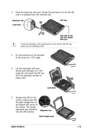
... on the socket and the socket contacts are not bent. Top:Line In Center:Line Out Below:Mic In P5VDC-X R P5VDC-X CPU Socket 775 Before installing the CPU, make sure that the socket box is facing towards you and the load lever is on your retailer immediately if the... if you see any damage to the socket contacts resulting from incorrect CPU installation/removal, or misplacement/loss/incorrect removal of the PnP cap. 1.6.1 Installing the CPU To install a CPU: 1. Contact your left. 1-8 Chapter 1: Hardware information ASUS will shoulder the cost of the motherboard, make sure that the PnP...
... on the socket and the socket contacts are not bent. Top:Line In Center:Line Out Below:Mic In P5VDC-X R P5VDC-X CPU Socket 775 Before installing the CPU, make sure that the socket box is facing towards you and the load lever is on your retailer immediately if the... if you see any damage to the socket contacts resulting from incorrect CPU installation/removal, or misplacement/loss/incorrect removal of the PnP cap. 1.6.1 Installing the CPU To install a CPU: 1. Contact your left. 1-8 Chapter 1: Hardware information ASUS will shoulder the cost of the motherboard, make sure that the PnP...
Motherboard Installation Guide
Page 21
...Load plate 5. Position the CPU on the socket, making sure that the gold triangle fixes on the bottom-left (B) until it is released from the load plate window to the socket pins, do not remove the PnP cap unless you . Alignment key Gold triangle mark ASUS P5VDC-X 1-9 Retention tab A ...Load lever PnP Cap B This side of the arrow to a 100º angle (A), then push the PnP cap from the retention tab. The socket alignment keys should face you are installing a CPU. 3.
...Load plate 5. Position the CPU on the socket, making sure that the gold triangle fixes on the bottom-left (B) until it is released from the load plate window to the socket pins, do not remove the PnP cap unless you . Alignment key Gold triangle mark ASUS P5VDC-X 1-9 Retention tab A ...Load lever PnP Cap B This side of the arrow to a 100º angle (A), then push the PnP cap from the retention tab. The socket alignment keys should face you are installing a CPU. 3.
Motherboard Installation Guide
Page 22
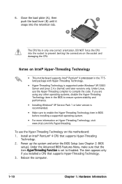
...BIOS before installing a supported operating system. • For more information on Hyper-Threading Technology, visit www.intel.com/info/hyperthreading. If you installed a CPU that supports Hyper-Threading Technology. 3. Power up the system and enter the BIOS Setup (see Chapter 2: BIOS setup). Under the Advanced BIOS Features Menu...;ts in only one correct orientation. Under Linux, use the Hyper-Threading Technology on the socket and damaging the CPU. DO NOT force the CPU into the retention tab. The item appears only if you are using any other operating systems, disable the Hyper-Threading...
...BIOS before installing a supported operating system. • For more information on Hyper-Threading Technology, visit www.intel.com/info/hyperthreading. If you installed a CPU that supports Hyper-Threading Technology. 3. Power up the system and enter the BIOS Setup (see Chapter 2: BIOS setup). Under the Advanced BIOS Features Menu...;ts in only one correct orientation. Under Linux, use the Hyper-Threading Technology on the socket and damaging the CPU. DO NOT force the CPU into the retention tab. The item appears only if you are using any other operating systems, disable the Hyper-Threading...
Motherboard Installation Guide
Page 23
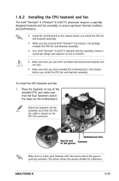
... such that you have installed the motherboard to the chassis before you install the CPU fan and heatsink assembly. • When you buy a boxed Intel® Pentium® 4 processor, the package includes the CPU fan and heatsink assembly. • Your Intel® Pentium® 4 LGA775...that the four fasteners match the holes on top of the groove pointing outward. (The photo shows the groove shaded for emphasis.) ASUS P5VDC-X 1-11 1.6.2 Installing the CPU heatsink and fan The Intel® Pentium® 4 /Pentium® D LGA775 processor requires a specially designed heatsink and fan ...
... such that you have installed the motherboard to the chassis before you install the CPU fan and heatsink assembly. • When you buy a boxed Intel® Pentium® 4 processor, the package includes the CPU fan and heatsink assembly. • Your Intel® Pentium® 4 LGA775...that the four fasteners match the holes on top of the groove pointing outward. (The photo shows the groove shaded for emphasis.) ASUS P5VDC-X 1-11 1.6.2 Installing the CPU heatsink and fan The Intel® Pentium® 4 /Pentium® D LGA775 processor requires a specially designed heatsink and fan ...

Motherboard Installation Guide
Page 24
Top:Line In Center:Line Out Below:Mic In P5VDC-X R CPU_FAN GND CPU FAN PWR CPU FAN IN CPU FAN PWM P5VDC-X CPU FAN Connector Do not forget to the connector on the motherboard labeled CPU_FAN. A A B A B B A 3. Connect the CPU fan cable to connect the CPU fan connector! Hardware monitoring errors can occur if you fail to secure the heatsink and B fan assembly in a diagonal sequence to plug this connector. 1-12 Chapter 1: Hardware information 2. Push down two fasteners at a time in place.
Top:Line In Center:Line Out Below:Mic In P5VDC-X R CPU_FAN GND CPU FAN PWR CPU FAN IN CPU FAN PWM P5VDC-X CPU FAN Connector Do not forget to the connector on the motherboard labeled CPU_FAN. A A B A B B A 3. Connect the CPU fan cable to connect the CPU fan connector! Hardware monitoring errors can occur if you fail to secure the heatsink and B fan assembly in a diagonal sequence to plug this connector. 1-12 Chapter 1: Hardware information 2. Push down two fasteners at a time in place.
Motherboard Installation Guide
Page 25
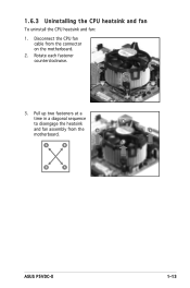
Rotate each fastener counterclockwise. 3. B A B B A ASUS P5VDC-X 1-13 Pull up two fasteners at a time in a diagonal sequence to disengage the heatsink B and fan assembly from the connector on the motherboard. 2. 1.6.3 Uninstalling the CPU heatsink and fan To uninstall the CPU heatsink and fan: 1. Disconnect the CPU fan cable from the A A motherboard.
Rotate each fastener counterclockwise. 3. B A B B A ASUS P5VDC-X 1-13 Pull up two fasteners at a time in a diagonal sequence to disengage the heatsink B and fan assembly from the connector on the motherboard. 2. 1.6.3 Uninstalling the CPU heatsink and fan To uninstall the CPU heatsink and fan: 1. Disconnect the CPU fan cable from the A A motherboard.

Motherboard Installation Guide
Page 36
Move the jumper cap from pins 1-2 (default) to overclocking. Top:Line In Center:Line Out Below:Mic In P5VDC-X R P5VDC-X Clear RTC RAM CLRTC 12 23 Normal (Default) Clear CMOS You do not need to clear the RTC when the system hangs due to pins 2-3. .... Except when clearing the RTC RAM, never remove the cap on pins 2-3 for about 5~10 seconds, then move the cap back to overclocking, use the C.P.R. (CPU Parameter Recall) feature. You can automatically reset parameter settings to clear the Real Time Clock (RTC) RAM in CMOS, which include system setup information such...
Move the jumper cap from pins 1-2 (default) to overclocking. Top:Line In Center:Line Out Below:Mic In P5VDC-X R P5VDC-X Clear RTC RAM CLRTC 12 23 Normal (Default) Clear CMOS You do not need to clear the RTC when the system hangs due to pins 2-3. .... Except when clearing the RTC RAM, never remove the cap on pins 2-3 for about 5~10 seconds, then move the cap back to overclocking, use the C.P.R. (CPU Parameter Recall) feature. You can automatically reset parameter settings to clear the Real Time Clock (RTC) RAM in CMOS, which include system setup information such...
Motherboard Installation Guide
Page 37
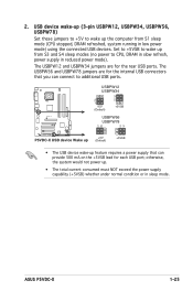
USB device wake-up (3-pin USBPW12, USBPW34, USBPW56, USBPW78) Set these jumpers to +5V to additional USB ports. ASUS P5VDC-X 1-25 The USBPW12 and USBPW34 jumpers are for the rear USB ports. The USBPW56 and USBPW78 jumpers are for the internal USB connectors...connected USB devices. Top:Line In Center:Line Out Below:Mic In P5VDC-X R USBPW12 USBPW34 2 1 +5V (Default) 3 2 +5VSB USBPW56 USBPW78 12 23 P5VDC-X USB device Wake up +5V (Default) +5VSB • The USB device wake-up from S1 sleep mode (CPU stopped, DRAM refreshed, system running in sleep mode. 2. otherwise, ...
USB device wake-up (3-pin USBPW12, USBPW34, USBPW56, USBPW78) Set these jumpers to +5V to additional USB ports. ASUS P5VDC-X 1-25 The USBPW12 and USBPW34 jumpers are for the rear USB ports. The USBPW56 and USBPW78 jumpers are for the internal USB connectors...connected USB devices. Top:Line In Center:Line Out Below:Mic In P5VDC-X R USBPW12 USBPW34 2 1 +5V (Default) 3 2 +5VSB USBPW56 USBPW78 12 23 P5VDC-X USB device Wake up +5V (Default) +5VSB • The USB device wake-up from S1 sleep mode (CPU stopped, DRAM refreshed, system running in sleep mode. 2. otherwise, ...

Motherboard Installation Guide
Page 42
... 1-30 Chapter 1: Hardware information 4. Top:Line In Center:Line Out Below:Mic In P5VDC-X R CPU_FAN GND CPU FAN PWR CPU FAN IN CPU FAN PWM PWR_FAN GND +12V Rotation CHA_FAN Rotation +12V GND P5VDC-X FAN Connectors 5. Do not forget to connect the fan cables to receive stereo audio ...inside the system may damage the motherboard components. Connect the fan cables to the fan connectors on the fan connectors! These are not jumpers! CPU, Chassis and Power Fan connectors (4-pin CPU_FAN, 3-pin CHA_FAN, 3-pin PWR_FAN) The fan connectors support cooling fans of 350mA~740mA (8.88W ...
... 1-30 Chapter 1: Hardware information 4. Top:Line In Center:Line Out Below:Mic In P5VDC-X R CPU_FAN GND CPU FAN PWR CPU FAN IN CPU FAN PWM PWR_FAN GND +12V Rotation CHA_FAN Rotation +12V GND P5VDC-X FAN Connectors 5. Do not forget to connect the fan cables to receive stereo audio ...inside the system may damage the motherboard components. Connect the fan cables to the fan connectors on the fan connectors! These are not jumpers! CPU, Chassis and Power Fan connectors (4-pin CPU_FAN, 3-pin CHA_FAN, 3-pin PWR_FAN) The fan connectors support cooling fans of 350mA~740mA (8.88W ...
Motherboard Installation Guide
Page 62
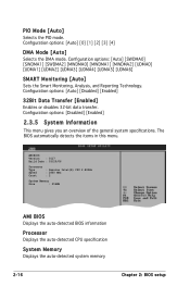
... the general system specifications. AMIBIOS Version : 0117 Build Date : 03/20/06 Processor Type : Genuine Intel(R) CPU 2.80GHz Speed : 2800 MHz Count : 2 System Memory Size : 256MB AMI BIOS Displays the auto-detected BIOS information Processor Displays the auto-detected... CPU specification System Memory Displays the auto-detected system memory 2-16 Chapter 2: BIOS setup Configuration options: [Auto] [Disabled...
... the general system specifications. AMIBIOS Version : 0117 Build Date : 03/20/06 Processor Type : Genuine Intel(R) CPU 2.80GHz Speed : 2800 MHz Count : 2 System Memory Size : 256MB AMI BIOS Displays the auto-detected BIOS information Processor Displays the auto-detected... CPU specification System Memory Displays the auto-detected system memory 2-16 Chapter 2: BIOS setup Configuration options: [Auto] [Disabled...

Motherboard Installation Guide
Page 63
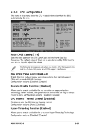
... can cause the system to malfunction. Frequencies higher than CPU manufacturer recommends are not guaranteed to achieve desired CPU internal frequency. Configuration options: [Manual] [Standard] [Overclock 5%] [Overclock 10%] [Overclock 20%] [Overclock 30%] ASUS P5VDC-X 2-17 JumperFree Configuration USB Configuration CPU Configuration Chipset Onboard Devices Configuration...
... can cause the system to malfunction. Frequencies higher than CPU manufacturer recommends are not guaranteed to achieve desired CPU internal frequency. Configuration options: [Manual] [Standard] [Overclock 5%] [Overclock 10%] [Overclock 20%] [Overclock 30%] ASUS P5VDC-X 2-17 JumperFree Configuration USB Configuration CPU Configuration Chipset Onboard Devices Configuration...

Motherboard Installation Guide
Page 64
... bus. Use the and keys to the table below for the correct Front Side Bus and CPU External Frequency settings. FSB/CPU External Frequency Synchronization Front Side Bus FSB 1066 FSB 800 FSB 533 CPU External Frequency 266 MHz 200 MHz 133 MHz AGP/PCI Frequency [Auto] Sets the AGP/PCI...: [Auto] [66.6/33.3] [75.0/37.5] [88.0/44.0] PCIE Frequency [Sync] Allows you set the AI Overclocking item to [Manual]. Refer to adjust the CPU frequency. You can also type the desired CPU frequency using the numeric keypad. The following item appears only when you to select the PCIE frequency mode...
... bus. Use the and keys to the table below for the correct Front Side Bus and CPU External Frequency settings. FSB/CPU External Frequency Synchronization Front Side Bus FSB 1066 FSB 800 FSB 533 CPU External Frequency 266 MHz 200 MHz 133 MHz AGP/PCI Frequency [Auto] Sets the AGP/PCI...: [Auto] [66.6/33.3] [75.0/37.5] [88.0/44.0] PCIE Frequency [Sync] Allows you set the AI Overclocking item to [Manual]. Refer to adjust the CPU frequency. You can also type the desired CPU frequency using the numeric keypad. The following item appears only when you to select the PCIE frequency mode...
Motherboard Installation Guide
Page 67
... [Enabled] Allows you to boot legacy operating systems that supports the lock free feature. Configuration options: [Disabled] [Enabled] ASUS P5VDC-X 2-21 The following item appears only when you install a CPU that cannot support CPUs with extended CPUID functions. The default value of this item to enable or disable the no execution...
... [Enabled] Allows you to boot legacy operating systems that supports the lock free feature. Configuration options: [Disabled] [Enabled] ASUS P5VDC-X 2-21 The following item appears only when you install a CPU that cannot support CPUs with extended CPUID functions. The default value of this item to enable or disable the no execution...
Motherboard Installation Guide
Page 75
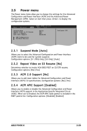
... disable the Advanced Configuration and Power Interface (ACPI) support in the RSDT pointer list. Configuration options: [Disabled] [Enabled] ASUS P5VDC-X 2-29 Select an item then press to invoke VGA BIOS POST on S3/STR resume. Configuration options: [No] [Yes] 2.5.4 ...2.5.2 Repost Video on S3 Resume ACPI 2.0 Support ACPI APIC Support APM Configuration Hardware Monitor [Auto] [No] [No] [Enabled] Configure CPU. 2.5.1 Suspend Mode [Auto] Select Screen Select Item Enter Go to Sub-screen F1 General Help F10 Save and Exit ESC Exit Allows you to change...
... disable the Advanced Configuration and Power Interface (ACPI) support in the RSDT pointer list. Configuration options: [Disabled] [Enabled] ASUS P5VDC-X 2-29 Select an item then press to invoke VGA BIOS POST on S3/STR resume. Configuration options: [No] [Yes] 2.5.4 ...2.5.2 Repost Video on S3 Resume ACPI 2.0 Support ACPI APIC Support APM Configuration Hardware Monitor [Auto] [No] [No] [Enabled] Configure CPU. 2.5.1 Suspend Mode [Auto] Select Screen Select Item Enter Go to Sub-screen F1 General Help F10 Save and Exit ESC Exit Allows you to change...
Motherboard Installation Guide
Page 76
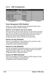
... the Power Management/APM function. This feature requires an ATX power supply that provides at least 1A on AC Power Loss [Enabled] [Last State] Configure CPU. 2.5.5 APM Configuration Power Management/APM Restore on the +5VSB lead.
... the Power Management/APM function. This feature requires an ATX power supply that provides at least 1A on AC Power Loss [Enabled] [Last State] Configure CPU. 2.5.5 APM Configuration Power Management/APM Restore on the +5VSB lead.


