
User Manual
Page 1
Motherboard
Motherboard

User Manual
Page 1
P5QL-EM Motherboard
P5QL-EM Motherboard
User Manual
Page 3
Contents Notices...vi Safety information vii About this guide vii P5QL-EM specifications summary ix Chapter 1 Product introduction 1.1 Welcome 1-1 1.2 Package contents 1-1 1.3 Special features 1-1 1.3.1 Product highlights 1-1 1.3.2 ASUS Special features 1-2 1.4 Before you proceed 1-4 1.5 Motherboard overview 1-5 1.5.1 Placement direction 1-5 1.5.2 Screw holes 1-5 1.5.3 Motherboard layout 1-6 1.5.4 Layout contents 1-7 1.6 Central Processing Unit (CPU 1-7 1.6.1 Installing the CPU 1-8 1.6.2 Installing the CPU heatsink and fan 1-10 1.6.3 Uninstalling...
Contents Notices...vi Safety information vii About this guide vii P5QL-EM specifications summary ix Chapter 1 Product introduction 1.1 Welcome 1-1 1.2 Package contents 1-1 1.3 Special features 1-1 1.3.1 Product highlights 1-1 1.3.2 ASUS Special features 1-2 1.4 Before you proceed 1-4 1.5 Motherboard overview 1-5 1.5.1 Placement direction 1-5 1.5.2 Screw holes 1-5 1.5.3 Motherboard layout 1-6 1.5.4 Layout contents 1-7 1.6 Central Processing Unit (CPU 1-7 1.6.1 Installing the CPU 1-8 1.6.2 Installing the CPU heatsink and fan 1-10 1.6.3 Uninstalling...
User Manual
Page 6
... a Class B digital device, pursuant to assure compliance with Part 15 of Communications. If this equipment. Canadian Department of the FCC Rules. DO NOT throw the motherboard in municipal waste. These limits are designed to enable proper reuse of the monitor to the graphics card is subject to the following measures: •...
... a Class B digital device, pursuant to assure compliance with Part 15 of Communications. If this equipment. Canadian Department of the FCC Rules. DO NOT throw the motherboard in municipal waste. These limits are designed to enable proper reuse of the monitor to the graphics card is subject to the following measures: •...
User Manual
Page 7
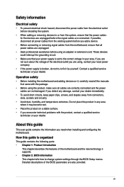
...About this guide is organized This guide contains the following parts: • Chapter 1: Product introduction This chapter describes the features of the motherboard and the new technology it supports. • Chapter 2: BIOS information This chapter tells how to fix it by yourself. Detailed descriptions ...of the electrical outlet you add a device. • Before connecting or removing signal cables from the motherboard, ensure that came with the product, contact a qualified service technician or your retailer. If you are not sure about the voltage of...
...About this guide is organized This guide contains the following parts: • Chapter 1: Product introduction This chapter describes the features of the motherboard and the new technology it supports. • Chapter 2: BIOS information This chapter tells how to fix it by yourself. Detailed descriptions ...of the electrical outlet you add a device. • Before connecting or removing signal cables from the motherboard, ensure that came with the product, contact a qualified service technician or your retailer. If you are not sure about the voltage of...

User Manual
Page 9
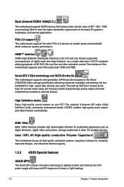
...; Hyper-Threading Technology *Refer to www.asus.com for yellow DIMMs when overclock to the total of four ranks(four sides in total) of 352MB Supports HDMI™ Technology with HDCP compliant with max. resolution 1920 x 1080p (@ 60Hz) Supports DVI-D with HDCP compliant with max. P5QL-EM specifications summary CPU. resolution 1900 x 1200... 4 x 240-pin DIMM sockets support unbufferred non-ECC DDR2-1066 (O.C.) / 800 / 667 / memory modules Supports up to 8 GB system memory * Due to chipset limitation, this motherboard only supports up to DDR2-1066.
...; Hyper-Threading Technology *Refer to www.asus.com for yellow DIMMs when overclock to the total of four ranks(four sides in total) of 352MB Supports HDMI™ Technology with HDCP compliant with max. resolution 1920 x 1080p (@ 60Hz) Supports DVI-D with HDCP compliant with max. P5QL-EM specifications summary CPU. resolution 1900 x 1200... 4 x 240-pin DIMM sockets support unbufferred non-ECC DDR2-1066 (O.C.) / 800 / 667 / memory modules Supports up to 8 GB system memory * Due to chipset limitation, this motherboard only supports up to DDR2-1066.

User Manual
Page 11
... with the list below. 1.2 Package contents Check your retailer. 1.3 Special features 1.3.1 Product highlights Green ASUS This motherboard and its packaging comply with the ASUS vision of ASUS quality motherboards! ASUS P5QL-EM 1-1 This is in 1 Serial ATA power cable 1 x Floppy disk drive cable 1 x I/O shield ASUS motherboard support DVD User Manual If any of the above items is one of Hazardous...
... with the list below. 1.2 Package contents Check your retailer. 1.3 Special features 1.3.1 Product highlights Green ASUS This motherboard and its packaging comply with the ASUS vision of ASUS quality motherboards! ASUS P5QL-EM 1-1 This is in 1 Serial ATA power cable 1 x Floppy disk drive cable 1 x I/O shield ASUS motherboard support DVD User Manual If any of the above items is one of Hazardous...
User Manual
Page 12
...-Go This motherboard supports next-generation SATA hard drives based on your PC! High Definition Audio Enjoy high-quality sound system on the Serial ATA(SATA) 3Gb/s storage specification,delivering enhanced scalability and doubling the bus bandwidth for durability, improved lifespan, and enhanced thermal capacity. 1.3.2 ASUS Special features ASUS EPU The ASUS EPU utilizes...
...-Go This motherboard supports next-generation SATA hard drives based on your PC! High Definition Audio Enjoy high-quality sound system on the Serial ATA(SATA) 3Gb/s storage specification,delivering enhanced scalability and doubling the bus bandwidth for durability, improved lifespan, and enhanced thermal capacity. 1.3.2 ASUS Special features ASUS EPU The ASUS EPU utilizes...

User Manual
Page 13
... Messengers (IM) like MSN, Skype, Google talk, QQ, and Yahoo! ASUS CrashFree BIOS 3 The ASUS CrashFree BIOS 3 allows users to USB drives only. ASUS P5QL-EM 1-3 See page 2-3 for details. This utility saves users' the cost and hassle of buying a replacement BIOS chip. It's a unique motherboard built-in touch with friends, or quickly check on the...
... Messengers (IM) like MSN, Skype, Google talk, QQ, and Yahoo! ASUS CrashFree BIOS 3 The ASUS CrashFree BIOS 3 allows users to USB drives only. ASUS P5QL-EM 1-3 See page 2-3 for details. This utility saves users' the cost and hassle of buying a replacement BIOS chip. It's a unique motherboard built-in touch with friends, or quickly check on the...
User Manual
Page 14
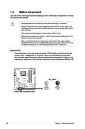
... antistatic pad or in the bag that came with a standby power LED that lights up to the motherboard, peripherals, and/or components. P5QL-EM P5QL-EM.Onboard.LED R SB_PWR ON Standby Power OFF Powered Off 1-4 Chapter 1: Product introduction Failure to do ...so may cause severe damage to indicate that the system is ON, in sleep mode, or in any component, ensure that the ATX power supply is detached from the power supply. Onboard LED The motherboard...
... antistatic pad or in the bag that came with a standby power LED that lights up to the motherboard, peripherals, and/or components. P5QL-EM P5QL-EM.Onboard.LED R SB_PWR ON Standby Power OFF Powered Off 1-4 Chapter 1: Product introduction Failure to do ...so may cause severe damage to indicate that the system is ON, in sleep mode, or in any component, ensure that the ATX power supply is detached from the power supply. Onboard LED The motherboard...
User Manual
Page 15
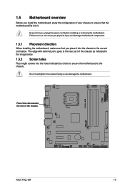
... with external ports goes to the rear part of the chassis as indicated in the correct orientation. the rear of the chassis P5QL-EM R ASUS P5QL-EM 1-5 Doing so can cause you physical injury and damage motherboard components. 1.5.1 Placement direction When installing the motherboard, make sure that you unplug the power cord before installing or removing the...
... with external ports goes to the rear part of the chassis as indicated in the correct orientation. the rear of the chassis P5QL-EM R ASUS P5QL-EM 1-5 Doing so can cause you physical injury and damage motherboard components. 1.5.1 Placement direction When installing the motherboard, make sure that you unplug the power cord before installing or removing the...
User Manual
Page 16
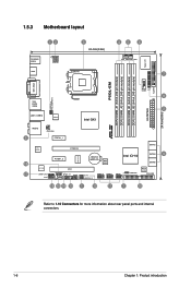
1.5.3 Motherboard layout 123 3 24.4cm(9.6in) 45 6 PS/2KBMS USB56 HDMI ATX12V LGA775 CPU_FAN PWR_FAN 7 Super I/O FLOPPY DDR2 DIMM_B1 (64 bit,240-pin module) DDR2 DIMM_B2 (64 bit,240-pin module) DDR2 DIMM_A1 (64 bit,240-pin module) DDR2 DIMM_A2 (64 bit,240-pin module) P5QL-EM DVI_VGA USBPW1-4 PS2_USBPW5-6 1394 ESATA USB34 LAN1_USB12...
1.5.3 Motherboard layout 123 3 24.4cm(9.6in) 45 6 PS/2KBMS USB56 HDMI ATX12V LGA775 CPU_FAN PWR_FAN 7 Super I/O FLOPPY DDR2 DIMM_B1 (64 bit,240-pin module) DDR2 DIMM_B2 (64 bit,240-pin module) DDR2 DIMM_A1 (64 bit,240-pin module) DDR2 DIMM_A2 (64 bit,240-pin module) P5QL-EM DVI_VGA USBPW1-4 PS2_USBPW5-6 1394 ESATA USB34 LAN1_USB12...

User Manual
Page 17
... before installing the CPU. • Connect the chassis fan cable to the CHA_FAN connector to the PnP cap/socket contacts/motherboard components. ASUS P5QL-EM 1-7 Serial port connectors (10-1 pin COM1) 7. ICH10 Serial ATA connectors (7-pin SATA1-6) 10. System panel connector (20...stability. • Upon purchase of repair only if the damage is shipment/ transit-related. • Keep the cap after installing the motherboard. ATX power connectors (24-pin EATXPWR, 4-pin ATX12V) 3. 1.5.4 Layout contents Connectors/Jumpers/Slots 1. LGA775 CPU Socket 4. DDR2 DIMM slots 5....
... before installing the CPU. • Connect the chassis fan cable to the CHA_FAN connector to the PnP cap/socket contacts/motherboard components. ASUS P5QL-EM 1-7 Serial port connectors (10-1 pin COM1) 7. ICH10 Serial ATA connectors (7-pin SATA1-6) 10. System panel connector (20...stability. • Upon purchase of repair only if the damage is shipment/ transit-related. • Keep the cap after installing the motherboard. ATX power connectors (24-pin EATXPWR, 4-pin ATX12V) 3. 1.5.4 Layout contents Connectors/Jumpers/Slots 1. LGA775 CPU Socket 4. DDR2 DIMM slots 5....
User Manual
Page 18
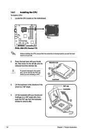
... to the socket pins, do not remove the PnP cap unless you and the load lever is on the motherboard. Retention tab A B Load lever PnP cap Load plate 4B 4A 3 1-8 Chapter 1: Product introduction P5QL-EM R P5QL-EM.CPU.Socket.775 Before installing the CPU, ensure that the socket box is facing towards you are installing...
... to the socket pins, do not remove the PnP cap unless you and the load lever is on the motherboard. Retention tab A B Load lever PnP cap Load plate 4B 4A 3 1-8 Chapter 1: Product introduction P5QL-EM R P5QL-EM.CPU.Socket.775 Before installing the CPU, ensure that the socket box is facing towards you are installing...

User Manual
Page 19
The motherboard supports Intel® LGA775 processors with preapplied thermal paste. DO NOT eat the Thermal Interface Material. To prevent contaminating the paste, DO NOT spread the ... Material to the exposed area of the socket then fit the socket alignment key into the A retention tab. If it snaps into the CPU notch. B ASUS P5QL-EM 1-9 CPU notch Gold triangle mark Alignment key 6.
The motherboard supports Intel® LGA775 processors with preapplied thermal paste. DO NOT eat the Thermal Interface Material. To prevent contaminating the paste, DO NOT spread the ... Material to the exposed area of the socket then fit the socket alignment key into the A retention tab. If it snaps into the CPU notch. B ASUS P5QL-EM 1-9 CPU notch Gold triangle mark Alignment key 6.

User Manual
Page 20
... a separate CPU heatsink and fan assembly, make sure that the four fasteners B match the holes on the motherboard. 2. The illustration above is for reference only. 3. P5QL-EM CPU_FAN Do not forget to the connector on top of CPU heatsink and fan assembly may differ, but the installation... steps and fucntions should remain the same. Place the heatsink on the motherboard labeled CPU_FAN. CPU FAN PWM CPU FAN IN CPU FAN PWR GND R P5QL-EM.CPU.Fan.Connector 1-10 Chapter 1: Product introduction Hardware monitoring errors can occur if you install...
... a separate CPU heatsink and fan assembly, make sure that the four fasteners B match the holes on the motherboard. 2. The illustration above is for reference only. 3. P5QL-EM CPU_FAN Do not forget to the connector on top of CPU heatsink and fan assembly may differ, but the installation... steps and fucntions should remain the same. Place the heatsink on the motherboard labeled CPU_FAN. CPU FAN PWM CPU FAN IN CPU FAN PWR GND R P5QL-EM.CPU.Fan.Connector 1-10 Chapter 1: Product introduction Hardware monitoring errors can occur if you install...

User Manual
Page 21
... and fan assembly from the motherboard. 1.7 System memory 1.7.1 Overview The motherboard comes with four Double Data Rate 2 (DDR2) Dual Inline Memory Modules (DIMM) sockets. A B B A 4. The figure illustrates the location of the DDR2 DIMM sockets: DIMM_A1 DIMM_A2 DIMM_B1 DIMM_B2 112 Pins P5QL-EM R 128 Pins P5QL-EM.240-pin.DDR2.DIMM.Sockets ASUS P5QL-EM 1-11 B 2. Rotate each fastener counterclockwise...
... and fan assembly from the motherboard. 1.7 System memory 1.7.1 Overview The motherboard comes with four Double Data Rate 2 (DDR2) Dual Inline Memory Modules (DIMM) sockets. A B B A 4. The figure illustrates the location of the DDR2 DIMM sockets: DIMM_A1 DIMM_A2 DIMM_B1 DIMM_B2 112 Pins P5QL-EM R 128 Pins P5QL-EM.240-pin.DDR2.DIMM.Sockets ASUS P5QL-EM 1-11 B 2. Rotate each fastener counterclockwise...
User Manual
Page 22
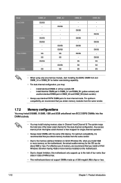
...one memory module, start installing the DDR2 DIMM from the higher-sized channel is recommended that you install 4GB or more memory installed on the motherboard, the actual usable memory for the OS can be about 3GB or less. install identical DIMM pair in DIMM_A1 and DIMM_B1 (yellow sockets)...single-channel operation. • Always install DIMMs with the same CAS latency. install identical DIMMs in total) of RAM at max. • This motherboard does not support DIMMs made up of the lower-sized channel for dual channel mode. The system maps the total size of 256 megabit (Mb...
...one memory module, start installing the DDR2 DIMM from the higher-sized channel is recommended that you install 4GB or more memory installed on the motherboard, the actual usable memory for the OS can be about 3GB or less. install identical DIMM pair in DIMM_A1 and DIMM_B1 (yellow sockets)...single-channel operation. • Always install DIMMs with the same CAS latency. install identical DIMMs in total) of RAM at max. • This motherboard does not support DIMMs made up of the lower-sized channel for dual channel mode. The system maps the total size of 256 megabit (Mb...

User Manual
Page 26
... Chapter 1: Product introduction Failure to do so can cause severe damage to avoid damaging the DIMM. 3. Firmly insert the DIMM into a socket to both the motherboard and the components. 1. Simultaneously press the retaining clips outward to unlock the DIMM. 1.7.3 Installing a DIMM Unplug the power supply before adding or removing DIMMs or...
... Chapter 1: Product introduction Failure to do so can cause severe damage to avoid damaging the DIMM. 3. Firmly insert the DIMM into a socket to both the motherboard and the components. 1. Simultaneously press the retaining clips outward to unlock the DIMM. 1.7.3 Installing a DIMM Unplug the power supply before adding or removing DIMMs or...

User Manual
Page 27
...Chapter 2 for the card. 2. 1.8 Expansion slots In the future, you may cause you physical injury and damage motherboard components. 1.8.1 Installing an expansion card To install an expansion card: 1. Before installing the expansion card, read the... documentation that came with the PCI Express specifications. 1.8.6 PCI Express x16 slot This motherboard supports a PCI Express x16 graphics card that they support. Failure to do not need to use . 4. ... the card. 3. Keep the screw for the expansion card. ASUS P5QL-EM 1-17 Turn on BIOS setup. 2.
...Chapter 2 for the card. 2. 1.8 Expansion slots In the future, you may cause you physical injury and damage motherboard components. 1.8.1 Installing an expansion card To install an expansion card: 1. Before installing the expansion card, read the... documentation that came with the PCI Express specifications. 1.8.6 PCI Express x16 slot This motherboard supports a PCI Express x16 graphics card that they support. Failure to do not need to use . 4. ... the card. 3. Keep the screw for the expansion card. ASUS P5QL-EM 1-17 Turn on BIOS setup. 2.


