
User Manual
Page 9
... Intel® Hyper-Threading Technology *Refer to www.asus.com for Intel CPU support list Intel G43 Intel ICH10... limitation, this motherboard only supports up to DDR2-1066. Integrated Intel GMA X4500 graphics with DirectX10 support Maximum shared memory of RAM at back panel...) 8 MB Flash ROM, AMI BIOS, Special H/W write protection, PnP, DMI v2.0, WfM2.0, SMBIOS 2.5, ACPI Realtek ALC1200 8-channel High Definition Audio CODEC Supports S/PDIF out interface Audio Jack-dectect, Multi-Streaming and Jack-Retasking Technology (continued on the next page) ix P5QL-EM...
... Intel® Hyper-Threading Technology *Refer to www.asus.com for Intel CPU support list Intel G43 Intel ICH10... limitation, this motherboard only supports up to DDR2-1066. Integrated Intel GMA X4500 graphics with DirectX10 support Maximum shared memory of RAM at back panel...) 8 MB Flash ROM, AMI BIOS, Special H/W write protection, PnP, DMI v2.0, WfM2.0, SMBIOS 2.5, ACPI Realtek ALC1200 8-channel High Definition Audio CODEC Supports S/PDIF out interface Audio Jack-dectect, Multi-Streaming and Jack-Retasking Technology (continued on the next page) ix P5QL-EM...

User Manual
Page 17
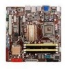
... the damage is on the LGA775 socket. • The product warranty does not cover damage to the PnP cap/socket contacts/motherboard components. ATX power connectors (24-pin EATXPWR, 4-pin ATX12V) 3. Serial port connectors (10-1 pin COM1) 7. Chassis intrusion connector (4-1 ..., USB910, and USB1112) 12. Clear RTC RAM (3-pin CLRTC) 13. 1.5.4 Layout contents Connectors/Jumpers/Slots 1. System panel connector (20-8 pin PANEL) 14. USB device wake-up (3-pin PS2_USBPW) 2. Optical drive audio connector (4-pin CD) 16. ASUS P5QL-EM 1-7 Floppy disk drive connector (34-1 pin...
... the damage is on the LGA775 socket. • The product warranty does not cover damage to the PnP cap/socket contacts/motherboard components. ATX power connectors (24-pin EATXPWR, 4-pin ATX12V) 3. Serial port connectors (10-1 pin COM1) 7. Chassis intrusion connector (4-1 ..., USB910, and USB1112) 12. Clear RTC RAM (3-pin CLRTC) 13. 1.5.4 Layout contents Connectors/Jumpers/Slots 1. System panel connector (20-8 pin PANEL) 14. USB device wake-up (3-pin PS2_USBPW) 2. Optical drive audio connector (4-pin CD) 16. ASUS P5QL-EM 1-7 Floppy disk drive connector (34-1 pin...
User Manual
Page 22
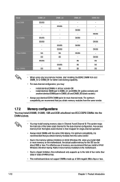
...sizes in DIMM_A2 and DIMM_B2 (black sockets) • Always use of memory, we recommend that you install 4GB or more memory installed on the motherboard, the actual usable memory for the dual-channel configuration. For optimum compatibility, we recommend that you obtain memory modules from the same vendor. •... in all four sockets OR - Mode One DIMM Two DIMMs Three DIMMs Four DIMMs DIMM_A1 DS/SS - install identical DIMMs in total) of RAM at max. • This motherboard does not support DIMMs made up of the lower-sized channel for the OS can be about 3GB or less.
...sizes in DIMM_A2 and DIMM_B2 (black sockets) • Always use of memory, we recommend that you install 4GB or more memory installed on the motherboard, the actual usable memory for the dual-channel configuration. For optimum compatibility, we recommend that you obtain memory modules from the same vendor. •... in all four sockets OR - Mode One DIMM Two DIMMs Three DIMMs Four DIMMs DIMM_A1 DS/SS - install identical DIMMs in total) of RAM at max. • This motherboard does not support DIMMs made up of the lower-sized channel for the OS can be about 3GB or less.

User Manual
Page 28
...the power supply or unplug and plug the power cord before you to pins 1-2. 3. P5QL-EM R P5QL-EM.Clear.RTC.RAM CLRTC 12 23 Normal Clear CMOS (Default) 1-18 Chapter 1: Product introduction Except when clearing the RTC RAM, never remove the cap on pins 2-3 for about 5-10 seconds, then move the... jumper again to overclocking, use the C.P.R. The onboard button cell battery powers the RAM data in CMOS. Turn OFF the computer and unplug the power cord. 2. Keep the cap on CLRTC jumper default position. For system ...
...the power supply or unplug and plug the power cord before you to pins 1-2. 3. P5QL-EM R P5QL-EM.Clear.RTC.RAM CLRTC 12 23 Normal Clear CMOS (Default) 1-18 Chapter 1: Product introduction Except when clearing the RTC RAM, never remove the cap on pins 2-3 for about 5-10 seconds, then move the... jumper again to overclocking, use the C.P.R. The onboard button cell battery powers the RAM data in CMOS. Turn OFF the computer and unplug the power cord. 2. Keep the cap on CLRTC jumper default position. For system ...

User Manual
Page 47
... This motherboard supports a programmable Serial Peripheral Interface (SPI) chip that you can update using the provided utility described in section "2.1 Managing and updating your system using the BIOS Setup program so that the computer can recognize these changes and record them in the CMOS RAM of ..., load the default settings to use as possible. The SPI chip on . If you are installing a motherboard, reconfiguring your data or system. We recommend to enter the Setup utility; ASUS P5QL-EM 2-7 See section 2.8 Exit Menu. • The BIOS setup screens shown in the future. Use the ...
... This motherboard supports a programmable Serial Peripheral Interface (SPI) chip that you can update using the provided utility described in section "2.1 Managing and updating your system using the BIOS Setup program so that the computer can recognize these changes and record them in the CMOS RAM of ..., load the default settings to use as possible. The SPI chip on . If you are installing a motherboard, reconfiguring your data or system. We recommend to enter the Setup utility; ASUS P5QL-EM 2-7 See section 2.8 Exit Menu. • The BIOS setup screens shown in the future. Use the ...

User Manual
Page 58
When set to RAM) sleep state (default). Configuration options: [Power Off] [Power On] [Last ...you to select the Advanced Configuration and Power Interface (ACPI) state to generate a wake event. This feature requires an ATX power supply that provides at least 1A on the +5VSB lead. Configuration options: [Disabled] [Enabled] Resume On Ring...this parameter allows you to enable or disable RI to be resumed at least 1A on the +5VSB lead. This feature requires an ATX power supply that provides at any time. [S3 Only] - Configuration options: [S1 (POS) Only] [S3 Only] [Auto...
When set to RAM) sleep state (default). Configuration options: [Power Off] [Power On] [Last ...you to select the Advanced Configuration and Power Interface (ACPI) state to generate a wake event. This feature requires an ATX power supply that provides at least 1A on the +5VSB lead. Configuration options: [Disabled] [Enabled] Resume On Ring...this parameter allows you to enable or disable RI to be resumed at least 1A on the +5VSB lead. This feature requires an ATX power supply that provides at any time. [S3 Only] - Configuration options: [S1 (POS) Only] [S3 Only] [Auto...

User Manual
Page 61
...you can clear it by erasing the CMOS Real Time Clock (RTC) RAM. After you to the Setup utility. To change other items appear to allow change the user password. Configuration options: [Setup] [Always] ASUS P5QL-EM 2-21 See section "1.9 Jumper" for user password when accessing the Setup...other security settings. Select the Change User Password item and press . 2. After you have set a password, this item to erase the RTC RAM. Full Access allows viewing and changing all the fields in the Setup utility. To clear the supervisor password, select the Change Supervisor Password then...
...you can clear it by erasing the CMOS Real Time Clock (RTC) RAM. After you to the Setup utility. To change other items appear to allow change the user password. Configuration options: [Setup] [Always] ASUS P5QL-EM 2-21 See section "1.9 Jumper" for user password when accessing the Setup...other security settings. Select the Change User Password item and press . 2. After you have set a password, this item to erase the RTC RAM. Full Access allows viewing and changing all the fields in the Setup utility. To clear the supervisor password, select the Change Supervisor Password then...

User Manual
Page 63
...window appears. When you made to the non-volatile RAM. F10 key can be used for a confirmation before saving the values to the Setup program. When you select this option or if you made and restore the previously saved values. ASUS P5QL-EM 2-23 menu. An onboard backup battery sustains the ...CMOS RAM so it stays on the Setup menus. If you press , a confirmation window appears. Select Screen Pressing does ...
...window appears. When you made to the non-volatile RAM. F10 key can be used for a confirmation before saving the values to the Setup program. When you select this option or if you made and restore the previously saved values. ASUS P5QL-EM 2-23 menu. An onboard backup battery sustains the ...CMOS RAM so it stays on the Setup menus. If you press , a confirmation window appears. Select Screen Pressing does ...


