User Manual
Page 4
...slots 2-21 2.5.7 Universal PCI Express x16 slot 2-21 2.6 Jumpers 2-23 2.7 Onboard switches 2-25 2.8 Connectors 2-26 2.8.1 Rear panel connectors 2-26 2.8.2 Internal connectors 2-28 2.9 Starting up for the first time 2-41 2.10 Turning off the computer 2-42 ...OS shut down function 2-42 2.10.2 Using the dual function power switch 2-42 Chapter 3: BIOS setup 3.1 Managing and updating your BIOS 3-1 3.1.1 ASUS Update utility 3-1 3.1.2 ASUS EZ Flash 2 utility 3-4 3.1.3 AFUDOS utility 3-5 3.2 BIOS setup program 3-7 3.2.1 BIOS menu screen 3-8 3.2.2 Menu bar 3-8 3.2.3 Navigation keys 3-8...
...slots 2-21 2.5.7 Universal PCI Express x16 slot 2-21 2.6 Jumpers 2-23 2.7 Onboard switches 2-25 2.8 Connectors 2-26 2.8.1 Rear panel connectors 2-26 2.8.2 Internal connectors 2-28 2.9 Starting up for the first time 2-41 2.10 Turning off the computer 2-42 ...OS shut down function 2-42 2.10.2 Using the dual function power switch 2-42 Chapter 3: BIOS setup 3.1 Managing and updating your BIOS 3-1 3.1.1 ASUS Update utility 3-1 3.1.2 ASUS EZ Flash 2 utility 3-4 3.1.3 AFUDOS utility 3-5 3.2 BIOS setup program 3-7 3.2.1 BIOS menu screen 3-8 3.2.2 Menu bar 3-8 3.2.3 Navigation keys 3-8...

User Manual
Page 13
... tuning from 100MHz up to 180MHz at 1MHz increment - P5Q-E Series specifications summary IEEE 1394 Audio USB ASUS unique features ASUS stylish features ASUS exclusive overclocking features LSI® L-FW3227 controller supports 2 x IEEE 1394a ports (one at back panel. Supports Jack-Detecting, Multi-streaming, and Front Panel Jack-Retasking - Coaxial / Optical S/PDIF out ports at 0.00625V...
... tuning from 100MHz up to 180MHz at 1MHz increment - P5Q-E Series specifications summary IEEE 1394 Audio USB ASUS unique features ASUS stylish features ASUS exclusive overclocking features LSI® L-FW3227 controller supports 2 x IEEE 1394a ports (one at back panel. Supports Jack-Detecting, Multi-streaming, and Front Panel Jack-Retasking - Coaxial / Optical S/PDIF out ports at 0.00625V...
User Manual
Page 14
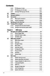
P5Q-E specifications summary Back Panel I/O ports Internal I/O connectors BIOS features Manageability Support DVD contents Form factor 1...SATA connectors (Red) 1 x CPU Fan connector 3 x Chassis Fan connectors 1 x Power Fan connector 1 x IEEE1394a connector Front panel audio connector 1 x S/PDIF Out Header Chassis Intrusion connector CD audio in 2 x Drive Xpert SATA connectors (Orange) 24-pin ATX...WOL by PME, WOR by PME, WOR by Ring, PXE, Chassis Intrusion Drivers ASUS Express Gate ASUS PC Probe II ASUS Update ASUS AI Suite Image-Editing Suite Anti-virus software (OEM version) ATX Form Factor, 12...
P5Q-E specifications summary Back Panel I/O ports Internal I/O connectors BIOS features Manageability Support DVD contents Form factor 1...SATA connectors (Red) 1 x CPU Fan connector 3 x Chassis Fan connectors 1 x Power Fan connector 1 x IEEE1394a connector Front panel audio connector 1 x S/PDIF Out Header Chassis Intrusion connector CD audio in 2 x Drive Xpert SATA connectors (Orange) 24-pin ATX...WOL by PME, WOR by PME, WOR by Ring, PXE, Chassis Intrusion Drivers ASUS Express Gate ASUS PC Probe II ASUS Update ASUS AI Suite Image-Editing Suite Anti-virus software (OEM version) ATX Form Factor, 12...

User Manual
Page 17
... Cables 1 x 2-port Serial ATA power cables 4 x Serial ATA signal cables 1 x Ultra DMA 133/100/66 cable Accessories 1 x ASUS Q-Shield (I/O shield) 1 x ASUS Q-Connector Kit (USB, 1394, system panel; ASUS P5Q-E Series 1-1 The motherboard delivers a host of new features and latest technologies, making it , check the items in the long line of the above items is ...
... Cables 1 x 2-port Serial ATA power cables 4 x Serial ATA signal cables 1 x Ultra DMA 133/100/66 cable Accessories 1 x ASUS Q-Shield (I/O shield) 1 x ASUS Q-Connector Kit (USB, 1394, system panel; ASUS P5Q-E Series 1-1 The motherboard delivers a host of new features and latest technologies, making it , check the items in the long line of the above items is ...
User Manual
Page 22
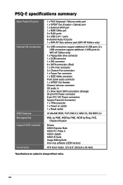
...chips, a main BIOS and a backup BIOS. See page 2-40 for details. See page 3-41 for details. ASUS DieHard BIOS The AUS DieHard BIOS consists of connecting the system panel cables one at a time and avoiding wrong cable connections. The technology saves users the hassle of data via the ...network cable - See page 2-25 for details. 1-6 Chapter 1: Product Introduction ASUS AI Direct Link AI Direct Link can restore ...
...chips, a main BIOS and a backup BIOS. See page 2-40 for details. See page 3-41 for details. ASUS DieHard BIOS The AUS DieHard BIOS consists of connecting the system panel cables one at a time and avoiding wrong cable connections. The technology saves users the hassle of data via the ...network cable - See page 2-25 for details. 1-6 Chapter 1: Product Introduction ASUS AI Direct Link AI Direct Link can restore ...
User Manual
Page 28
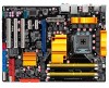
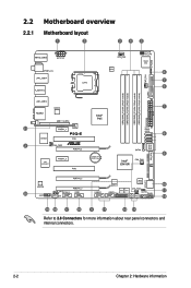
2.2 Motherboard overview 2.2.1 Motherboard layout Refer to 2.8 Connectors for more information about rear panel connectors and internal connectors. 2-2 Chapter 2: Hardware information
2.2 Motherboard overview 2.2.1 Motherboard layout Refer to 2.8 Connectors for more information about rear panel connectors and internal connectors. 2-2 Chapter 2: Hardware information
User Manual
Page 29
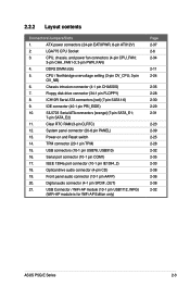
...; 3-pin CHA_FAN1-3; 3-pin PWR_FAN) 4. Chassis intrusion connector (4-1 pin CHASSIS) 7. Power-on and Reset switch 14. ICH10R Serial ATA connectors [red] (7-pin SATA1-6) 9. System panel connector (20-8 pin PANEL) 13. CPU / Northbridge overvoltage setting (3-pin OV_CPU; 3-pin OV_NB) 6. Clear RTC RAM (3-pin CLRTC) 12. ATX power connectors (24-pin EATXPWR, 8-pin ATX12V) 2. Serial... WiFi-AP Edition only) Page 2-37 2-6 2-34 2-11 2-24 2-35 2-28 2-30 2-29 2-31 2-23 2-39 2-25 2-28 2-32 2-35 2-33 2-38 2-36 2-38 2-32 ASUS P5Q-E Series 2-3 DDR2 DIMM slots 5.
...; 3-pin CHA_FAN1-3; 3-pin PWR_FAN) 4. Chassis intrusion connector (4-1 pin CHASSIS) 7. Power-on and Reset switch 14. ICH10R Serial ATA connectors [red] (7-pin SATA1-6) 9. System panel connector (20-8 pin PANEL) 13. CPU / Northbridge overvoltage setting (3-pin OV_CPU; 3-pin OV_NB) 6. Clear RTC RAM (3-pin CLRTC) 12. ATX power connectors (24-pin EATXPWR, 8-pin ATX12V) 2. Serial... WiFi-AP Edition only) Page 2-37 2-6 2-34 2-11 2-24 2-35 2-28 2-30 2-29 2-31 2-23 2-39 2-25 2-28 2-32 2-35 2-33 2-38 2-36 2-38 2-32 ASUS P5Q-E Series 2-3 DDR2 DIMM slots 5.
User Manual
Page 52
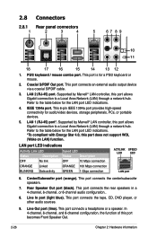
... Description OFF No link OFF 10 Mbps connection ORANGE Linked ORANGE 100 Mbps connection BLINKING Data activity GREEN 1 Gbps connection ACT/LINK SPEED LED LED LAN port 6. This port connects a headphone or a speaker. 2.8 Connectors 2.8.1 Rear panel connectors 1. PS/2 keyboard / mouse combo port. This port connects the rear speakers in a 4-channel, 6-channel, or...
... Description OFF No link OFF 10 Mbps connection ORANGE Linked ORANGE 100 Mbps connection BLINKING Data activity GREEN 1 Gbps connection ACT/LINK SPEED LED LED LAN port 6. This port connects a headphone or a speaker. 2.8 Connectors 2.8.1 Rear panel connectors 1. PS/2 keyboard / mouse combo port. This port connects the rear speakers in a 4-channel, 6-channel, or...
User Manual
Page 58
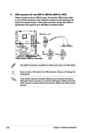
... that supports up to the USB connectors. Never connect a 1394 cable to 480 Mbps connection speed. If your chassis supports front panel USB ports, you can attach a front panel USB cable to these connectors, then install the module to a slot opening at the back of the system chassis. Doing so ...will damage the motherboard! Connect the USB cable to ASUS Q-Connector (USB, blue) first, and then install the Q-Connector (USB) to any ...
... that supports up to the USB connectors. Never connect a 1394 cable to 480 Mbps connection speed. If your chassis supports front panel USB ports, you can attach a front panel USB cable to these connectors, then install the module to a slot opening at the back of the system chassis. Doing so ...will damage the motherboard! Connect the USB cable to ASUS Q-Connector (USB, blue) first, and then install the Q-Connector (USB) to any ...
User Manual
Page 59
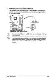
...cable to a slot opening at the back of the system chassis. Connect the 1394 cable to ASUS Q-Connector (1394, red) first, and then install the Q-Connector (1394) to the IEEE 1394a connector. ASUS P5Q-E Series 2-33 7. IEEE 1394a port connector (10-1 pin IE1394_2) This connector is for a ...IEEE 1394a port. You can attach a FireWire/1394 cable to this connector, then install the module to this connector if your chassis suppots the front panel IEEE1394 port. Doing ...
...cable to a slot opening at the back of the system chassis. Connect the 1394 cable to ASUS Q-Connector (1394, red) first, and then install the Q-Connector (1394) to the IEEE 1394a connector. ASUS P5Q-E Series 2-33 7. IEEE 1394a port connector (10-1 pin IE1394_2) This connector is for a ...IEEE 1394a port. You can attach a FireWire/1394 cable to this connector, then install the module to this connector if your chassis suppots the front panel IEEE1394 port. Doing ...
User Manual
Page 62
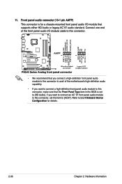
11. Refer to 3.5.4 Onboard Device Configuration for a chassis-mounted front panel audio I/O module that you connect a high-definition front panel audio module to this connector to avail of the front panel audio I/O module cable to this connector, set to this connector. • We recommend that supports either HD ...Audio or legacy AC`97 audio standard. If you want to connect an AC' 97 front panel audio module to [HD Audio]. Front panel audio connector (10-1 pin AAFP) This connector is set the item to this connector, make sure that the Front...
11. Refer to 3.5.4 Onboard Device Configuration for a chassis-mounted front panel audio I/O module that you connect a high-definition front panel audio module to this connector to avail of the front panel audio I/O module cable to this connector, set to this connector. • We recommend that supports either HD ...Audio or legacy AC`97 audio standard. If you want to connect an AC' 97 front panel audio module to [HD Audio]. Front panel audio connector (10-1 pin AAFP) This connector is set the item to this connector, make sure that the Front...
User Manual
Page 65
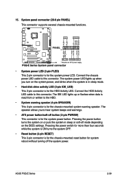
.... Pressing the power button turns the system on the BIOS settings. System panel connector (20-8 pin PANEL) This connector supports several chassis-mounted functions. • System power LED (2-pin PLED) This 2-pin connector is for the chassis-mounted system warning speaker. ASUS P5Q-E Series 2-39 Pressing the power switch for more than four seconds...
.... Pressing the power button turns the system on the BIOS settings. System panel connector (20-8 pin PANEL) This connector supports several chassis-mounted functions. • System power LED (2-pin PLED) This 2-pin connector is for the chassis-mounted system warning speaker. ASUS P5Q-E Series 2-39 Pressing the power switch for more than four seconds...
User Manual
Page 66
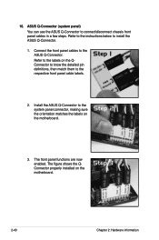
... the orientation matches the labels on the QConnector to know the detailed pin definitions, then match them to the respective front panel cable labels. 2. Refer to the ASUS Q-Connector. Connect the front panel cables to the labels on the motherboard. 3. The figure shows the QConnector properly installed on the motherboard. 2-40 Chapter 2: Hardware...
... the orientation matches the labels on the QConnector to know the detailed pin definitions, then match them to the respective front panel cable labels. 2. Refer to the ASUS Q-Connector. Connect the front panel cables to the labels on the motherboard. 3. The figure shows the QConnector properly installed on the motherboard. 2-40 Chapter 2: Hardware...
User Manual
Page 67
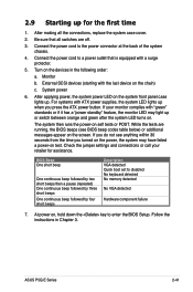
...system LED lights up for assistance. If you do not see BIOS beep codes table below) or additional messages appear on the devices in Chapter 3. ASUS P5Q-E Series 2-41 If your retailer for the first time 1. The system then runs the power-on the chain) c. Check the jumper settings and... has a "power standby" feature, the monitor LED may have failed a power-on . At power on the system front panel case lights up or switch between orange and green after the system LED turns on test. Connect the power cord to enter the BIOS Setup. After applying power, the system...
...system LED lights up for assistance. If you do not see BIOS beep codes table below) or additional messages appear on the devices in Chapter 3. ASUS P5Q-E Series 2-41 If your retailer for the first time 1. The system then runs the power-on the chain) c. Check the jumper settings and... has a "power standby" feature, the monitor LED may have failed a power-on . At power on the system front panel case lights up or switch between orange and green after the system LED turns on test. Connect the power cord to enter the BIOS Setup. After applying power, the system...
User Manual
Page 97
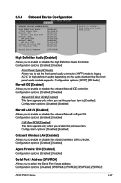
...] Enable or Disable High Definition Audio Controller High Definition Audio [Enabled] Allows you to set the previous item to [Enabled]. Configuration options: [Enabled] [Disabled] Front Panel Type [HD Audio] Allows you to enable or disable the onboard Marvell IDE controller. Configuration options: [Enabled] [Disabled] Agere Firewire 1394 [Enabled] Configuration options: [Enabled... [Disabled] This item appears only when you to select the Serial Port1 base address. Configuration options: [Disabled] [3F8/IRQ4] [2F8/IRQ3] [3E8/IRQ4] [2E8/IRQ3] ASUS P5Q-E Series 3-27
...] Enable or Disable High Definition Audio Controller High Definition Audio [Enabled] Allows you to set the previous item to [Enabled]. Configuration options: [Enabled] [Disabled] Front Panel Type [HD Audio] Allows you to enable or disable the onboard Marvell IDE controller. Configuration options: [Enabled] [Disabled] Agere Firewire 1394 [Enabled] Configuration options: [Enabled... [Disabled] This item appears only when you to select the Serial Port1 base address. Configuration options: [Disabled] [3F8/IRQ4] [2F8/IRQ3] [3E8/IRQ4] [2E8/IRQ3] ASUS P5Q-E Series 3-27
User Manual
Page 128
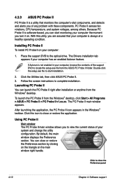
...the Windows® desktop. After launching the application, the PC Probe II icon appears in your system and change the utility configuration. 4.3.3 ASUS PC Probe II PC Probe II is always at a healthy operating condition. PC Probe II senses fan rotations, CPU temperature, and system...The Drivers installation tab appears if your computer: 1. If Autorun is software-based, you can close the Preference panel 4-12 Chapter 4: Software support Click the Utilities tab, then click ASUS PC Probe II. 3. The PC Probe II main window appears. By default, the main window displays the ...
...the Windows® desktop. After launching the application, the PC Probe II icon appears in your system and change the utility configuration. 4.3.3 ASUS PC Probe II PC Probe II is always at a healthy operating condition. PC Probe II senses fan rotations, CPU temperature, and system...The Drivers installation tab appears if your computer: 1. If Autorun is software-based, you can close the Preference panel 4-12 Chapter 4: Software support Click the Utilities tab, then click ASUS PC Probe II. 3. The PC Probe II main window appears. By default, the main window displays the ...
User Manual
Page 129
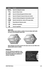
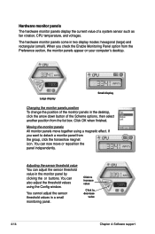
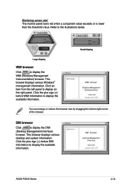
Click the box before each preference to the Monitor panels section for that sensor also turns red. Button Function Opens the Configuration window Opens the Report window Opens the Desktop Management Interface window Opens the ... the application Sensor alert When a system sensor detects a problem, the main window right handle turns red, as the illustrations below show. When displayed, the monitor panel for details. Refer to activate or deactivate. ASUS P5Q-E Series 4-13 Preference You can customize the application using the Preference section in the main window.
Click the box before each preference to the Monitor panels section for that sensor also turns red. Button Function Opens the Configuration window Opens the Report window Opens the Desktop Management Interface window Opens the ... the application Sensor alert When a system sensor detects a problem, the main window right handle turns red, as the illustrations below show. When displayed, the monitor panel for details. Refer to activate or deactivate. ASUS P5Q-E Series 4-13 Preference You can customize the application using the Preference section in the main window.
User Manual
Page 130
... modes: hexagonal (large) and rectangular (small). Moving the monitor panels All monitor panels move or reposition the panel independently. If you check the Enable Monitoring Panel option from the Preference section, the monitor panels appear on your computer's desktop. You can now move together using... another position from the list box. The hardware monitor panels come in a small monitoring panel. Large display Small display Changing the monitor panels position To change the position of the monitor panels in the monitor panel by clicking the or buttons. Click OK when finished....
... modes: hexagonal (large) and rectangular (small). Moving the monitor panels All monitor panels move or reposition the panel independently. If you check the Enable Monitoring Panel option from the Preference section, the monitor panels appear on your computer's desktop. You can now move together using... another position from the list box. The hardware monitor panels come in a small monitoring panel. Large display Small display Changing the monitor panels position To change the position of the monitor panels in the monitor panel by clicking the or buttons. Click OK when finished....
User Manual
Page 131
Click an item from the left panel to display the DMI (Desktop Management Interface) browser. This browser displays various Windows® management information. Click the plus sign (+) before DMI Information to display ... red when a component value exceeds or is lower than the threshold value. DMI browser Click to display on the right panel. ASUS P5Q-E Series 4-15 Refer to display the WMI (Windows Management Instrumentation) browser. Small display Large display WMI browser Click to the illustrations below. This browser displays ...
Click an item from the left panel to display the DMI (Desktop Management Interface) browser. This browser displays various Windows® management information. Click the plus sign (+) before DMI Information to display ... red when a component value exceeds or is lower than the threshold value. DMI browser Click to display on the right panel. ASUS P5Q-E Series 4-15 Refer to display the WMI (Windows Management Instrumentation) browser. Small display Large display WMI browser Click to the illustrations below. This browser displays ...
User Manual
Page 132
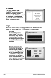
... Hard disk drive space usage The Hard Disk tab displays the used (blue) and the available HDD space. 4-16 Chapter 4: Software support The left panel of the two logical processors. Click a hard disk drive to display available information. The pie chart at the bottom of the window represents the used... of the tab lists all logical drives. Click the plus sign (+) before the PCI Information item to display the information on the right panel. Click to display the PCI (Peripheral Component Interconnect) browser. PCI browser Click to display the Usage browser.
... Hard disk drive space usage The Hard Disk tab displays the used (blue) and the available HDD space. 4-16 Chapter 4: Software support The left panel of the two logical processors. Click a hard disk drive to display available information. The pie chart at the bottom of the window represents the used... of the tab lists all logical drives. Click the plus sign (+) before the PCI Information item to display the information on the right panel. Click to display the PCI (Peripheral Component Interconnect) browser. PCI browser Click to display the Usage browser.


