
User Manual
Page 1
Motherboard P5Q-E Series
Motherboard P5Q-E Series
User Manual
Page 3
Contents Contents...iii Notices...viii Safety information ix About this guide x P5Q-E Series specifications summary xii Chapter 1: Product introduction 1.1 Welcome 1-1 1.2 Package contents 1-1 1.3 Special features 1-2 1.3.1 Product highlights 1-2 1.3.2 ASUS unique features 1-3 1.3.3 ASUS intelligent performance and overclocking features 1-7 Chapter 2: Hardware information 2.1 Before you proceed 2-1 2.2 Motherboard overview 2-2 2.2.1 Motherboard layout 2-2 2.2.2 Layout contents 2-3 2.2.3 Placement direction 2-4 2.2.4 Screw holes 2-4 2.3 Central Processing Unit (CPU 2-5 2.3.1 ...
Contents Contents...iii Notices...viii Safety information ix About this guide x P5Q-E Series specifications summary xii Chapter 1: Product introduction 1.1 Welcome 1-1 1.2 Package contents 1-1 1.3 Special features 1-2 1.3.1 Product highlights 1-2 1.3.2 ASUS unique features 1-3 1.3.3 ASUS intelligent performance and overclocking features 1-7 Chapter 2: Hardware information 2.1 Before you proceed 2-1 2.2 Motherboard overview 2-2 2.2.1 Motherboard layout 2-2 2.2.2 Layout contents 2-3 2.2.3 Placement direction 2-4 2.2.4 Screw holes 2-4 2.3 Central Processing Unit (CPU 2-5 2.3.1 ...

User Manual
Page 9
... about the voltage of the electrical outlet you add a device. • Before connecting or removing signal cables from the motherboard, ensure that all power cables are connected. Operation safety • Before installing the motherboard and adding devices on a stable surface. • If you detect any damage, contact your retailer. Do not place...
... about the voltage of the electrical outlet you add a device. • Before connecting or removing signal cables from the motherboard, ensure that all power cables are connected. Operation safety • Before installing the motherboard and adding devices on a stable surface. • If you detect any damage, contact your retailer. Do not place...

User Manual
Page 10
...Appendix describes the CPU features and technologies that may have to the ASUS contact information. 2. These documents are also provided. • Chapter 4: Software support This chapter describes the contents of the motherboard and the new technology it supports. • Chapter 2: Hardware ...the hardware setup procedures that you need when installing and configuring the motherboard. Detailed descriptions of the BIOS parameters are not part of the switches, jumpers, and connectors on ASUS hardware and software products. Optional documentation Your product package may include optional...
...Appendix describes the CPU features and technologies that may have to the ASUS contact information. 2. These documents are also provided. • Chapter 4: Software support This chapter describes the contents of the motherboard and the new technology it supports. • Chapter 2: Hardware ...the hardware setup procedures that you need when installing and configuring the motherboard. Detailed descriptions of the BIOS parameters are not part of the switches, jumpers, and connectors on ASUS hardware and software products. Optional documentation Your product package may include optional...

User Manual
Page 15
This chapter describes the motherboard features and the new technologies it supports. 1Product introduction
This chapter describes the motherboard features and the new technologies it supports. 1Product introduction

User Manual
Page 17
... Documentation User guide WiFi-AP Solo user guide (WiFi-AP Ediition Only) • The floppy disk drive cable is purchased separately. • If any of ASUS quality motherboards! Before you for the following items. Motherboard ASUS P5Q-E Series Cables 1 x 2-port Serial ATA power cables 4 x Serial ATA signal cables 1 x Ultra DMA 133/100/66 cable Accessories...
... Documentation User guide WiFi-AP Solo user guide (WiFi-AP Ediition Only) • The floppy disk drive cable is purchased separately. • If any of ASUS quality motherboards! Before you for the following items. Motherboard ASUS P5Q-E Series Cables 1 x 2-port Serial ATA power cables 4 x Serial ATA signal cables 1 x Ultra DMA 133/100/66 cable Accessories...
User Manual
Page 18
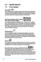
1.3 Special features 1.3.1 Product highlights Green ASUS This motherboard and its packaging comply with the European Union's Restriction on the use of available memory bandwidth and reduces the latency of Hazardous Substances (RoHS). See ... / 1066 / 800 FSB (Front Side Bus), PCIe 2.0, and multi-core CPUs. Intel® Core™2 Extreme / Core™ 2 Quad / Core™2 Duo Processor Support This motherboard supports the latest Intel® Core™ 2 Extreme / Core™ 2 Quad / Core™ 2 Duo processors in the new 45nm manufacturing process. See page 2-5 for details...
1.3 Special features 1.3.1 Product highlights Green ASUS This motherboard and its packaging comply with the European Union's Restriction on the use of available memory bandwidth and reduces the latency of Hazardous Substances (RoHS). See ... / 1066 / 800 FSB (Front Side Bus), PCIe 2.0, and multi-core CPUs. Intel® Core™2 Extreme / Core™ 2 Quad / Core™2 Duo Processor Support This motherboard supports the latest Intel® Core™ 2 Extreme / Core™ 2 Quad / Core™ 2 Duo processors in the new 45nm manufacturing process. See page 2-5 for details...

User Manual
Page 19
It's a unique motherboard built-in sleep mode, so users can utilize the most popular Instant Messengers (IM) like MSN, Skype, Google talk, QQ, and Yahoo! You can use Skype from bootup, Express Gate is in OS. What's more energy efficiency. ASUS 8-Phase Power Design Longer life & higher ...efficiency! High quality power components such as a network gateway for managing traffic between two separate networks. ASUS P5Q-E Series 1-3 Dual Gigabit LAN solution The integrated dual Gigabit LAN design allows a PC to serve as low RDS (on the weather...
It's a unique motherboard built-in sleep mode, so users can utilize the most popular Instant Messengers (IM) like MSN, Skype, Google talk, QQ, and Yahoo! You can use Skype from bootup, Express Gate is in OS. What's more energy efficiency. ASUS 8-Phase Power Design Longer life & higher ...efficiency! High quality power components such as a network gateway for managing traffic between two separate networks. ASUS P5Q-E Series 1-3 Dual Gigabit LAN solution The integrated dual Gigabit LAN design allows a PC to serve as low RDS (on the weather...

User Manual
Page 20
... users to dissipate heat these critical components generate. ASUS Quiet Thermal Solution ASUS Quiet Thermal solution makes system more stable and enhances the overclocking capability. The motherboard uses a special design on this motherboard is that lowers the temperature of the innovative heat...-noise cooling solution that the groundbreaking fanless design does not have lifetime problems as a chipset fan does. ASUS Power Saving Solution ASUS Power Saving solution intelligently and automatically provides balanced computing power and energy consumption. With auto phase switching for ...
... users to dissipate heat these critical components generate. ASUS Quiet Thermal Solution ASUS Quiet Thermal solution makes system more stable and enhances the overclocking capability. The motherboard uses a special design on this motherboard is that lowers the temperature of the innovative heat...-noise cooling solution that the groundbreaking fanless design does not have lifetime problems as a chipset fan does. ASUS Power Saving Solution ASUS Power Saving solution intelligently and automatically provides balanced computing power and energy consumption. With auto phase switching for ...
User Manual
Page 22
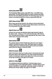
... or share large data files like movies or other media content. The ASUS DieHard BIOS can be stored in the CMOS or a separate file, giving users freedom to the motherboard. ASUS Q-Connector ASUS Q-Connector allows you to easily connect or disconnect the chassis front panel... cables to share and distribute their favorite settings. ASUS O.C. The technology saves users the hassle of connecting the system panel...
... or share large data files like movies or other media content. The ASUS DieHard BIOS can be stored in the CMOS or a separate file, giving users freedom to the motherboard. ASUS Q-Connector ASUS Q-Connector allows you to easily connect or disconnect the chassis front panel... cables to share and distribute their favorite settings. ASUS O.C. The technology saves users the hassle of connecting the system panel...

User Manual
Page 23
... each parameter. See pages 3-20-3-21 for details. ASUS P5Q-E Series 1-7 Update your screen. See page 4-23 for details. See page 3-35 and 4-9 for details. 1.3.3 ASUS intelligent performance and overclocking features AI Booster The ASUS AI Booster allows you to overclocking. When the system hangs...on your BIOS easily without the hassle of the motherboard BIOS allows automatic re-setting to the BIOS default settings in 0.02v steps to finetune voltages to overclocking, C.P.R. feature of booting the BIOS. ASUS MyLogo3™ This feature allows you to overclock the...
... each parameter. See pages 3-20-3-21 for details. ASUS P5Q-E Series 1-7 Update your screen. See page 4-23 for details. See page 3-35 and 4-9 for details. 1.3.3 ASUS intelligent performance and overclocking features AI Booster The ASUS AI Booster allows you to overclocking. When the system hangs...on your BIOS easily without the hassle of the motherboard BIOS allows automatic re-setting to the BIOS default settings in 0.02v steps to finetune voltages to overclocking, C.P.R. feature of booting the BIOS. ASUS MyLogo3™ This feature allows you to overclock the...

User Manual
Page 25
It includes description of the jumpers and connectors on the motherboard. 2 Hardware information This chapter lists the hardware setup procedures that you have to perform when installing system components.
It includes description of the jumpers and connectors on the motherboard. 2 Hardware information This chapter lists the hardware setup procedures that you have to perform when installing system components.

User Manual
Page 26
Chapter summary 2 2.1 Before you proceed 2-1 2.2 Motherboard overview 2-2 2.3 Central Processing Unit (CPU 2-5 2.4 System memory 2-11 2.5 Expansion slots 2-18 2.6 Jumpers 2-22 2.7 Onboard switches 2-24 2.8 Connectors 2-25 2.9 Starting up for the first time 2-40 2.10 Turning off the computer 2-41 ASUS P5Q-E Series
Chapter summary 2 2.1 Before you proceed 2-1 2.2 Motherboard overview 2-2 2.3 Central Processing Unit (CPU 2-5 2.4 System memory 2-11 2.5 Expansion slots 2-18 2.6 Jumpers 2-22 2.7 Onboard switches 2-24 2.8 Connectors 2-25 2.9 Starting up for the first time 2-40 2.10 Turning off the computer 2-41 ASUS P5Q-E Series

User Manual
Page 27
2.1 Before you proceed Take note of the following precautions before you install motherboard components or change any motherboard settings. • Unplug the power cord from the wall socket before touching any component. • Use a grounded wrist strap or touch a safely ...power supply case, before handling components to avoid damaging them due to static electricity. • Hold components by the edges to the motherboard, peripherals, and/or components. ASUS P5Q-E Series 2-1 Failure to do so may cause severe damage to avoid touching the ICs on them. • Whenever you uninstall any ...
2.1 Before you proceed Take note of the following precautions before you install motherboard components or change any motherboard settings. • Unplug the power cord from the wall socket before touching any component. • Use a grounded wrist strap or touch a safely ...power supply case, before handling components to avoid damaging them due to static electricity. • Hold components by the edges to the motherboard, peripherals, and/or components. ASUS P5Q-E Series 2-1 Failure to do so may cause severe damage to avoid touching the ICs on them. • Whenever you uninstall any ...
User Manual
Page 28
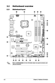
2.2 Motherboard overview 2.2.1 Motherboard layout Refer to 2.8 Connectors for more information about rear panel connectors and internal connectors. 2-2 Chapter 2: Hardware information
2.2 Motherboard overview 2.2.1 Motherboard layout Refer to 2.8 Connectors for more information about rear panel connectors and internal connectors. 2-2 Chapter 2: Hardware information

User Manual
Page 30
Doing so can damage the motherboard. DO NOT overtighten the screws! Place this side towards the rear of the chassis as indicated in the correct orientation. The edge with external ports goes to the chassis. 2.2.3 Placement direction When installing the motherboard, make sure that you place it into the chassis in the image below. 2.2.4 Screw holes Place nine (9) screws into the holes indicated by circles to secure the motherboard to the rear part of the chassis 2-4 Chapter 2: Hardware information
Doing so can damage the motherboard. DO NOT overtighten the screws! Place this side towards the rear of the chassis as indicated in the correct orientation. The edge with external ports goes to the chassis. 2.2.3 Placement direction When installing the motherboard, make sure that you place it into the chassis in the image below. 2.2.4 Screw holes Place nine (9) screws into the holes indicated by circles to secure the motherboard to the rear part of the chassis 2-4 Chapter 2: Hardware information
User Manual
Page 31
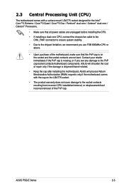
ASUS P5Q-E Series 2-5 ASUS will process Return Merchandise Authorization (RMA) requests only if the motherboard comes with a surface mount LGA775 socket designed for the Intel® Core™2 Extreme / Core™2 Quad / Core™2 Duo / Pentium® dual-core /...; Make sure that the PnP cap is shipment/transit-related. • Keep the cap after installing the motherboard. ASUS will shoulder the cost of the PnP cap. 2.3 Central Processing Unit (CPU) The motherboard comes with the cap on the socket and the socket contacts are not bent. Contact your retailer immediately if...
ASUS P5Q-E Series 2-5 ASUS will process Return Merchandise Authorization (RMA) requests only if the motherboard comes with a surface mount LGA775 socket designed for the Intel® Core™2 Extreme / Core™2 Quad / Core™2 Duo / Pentium® dual-core /...; Make sure that the PnP cap is shipment/transit-related. • Keep the cap after installing the motherboard. ASUS will shoulder the cost of the PnP cap. 2.3 Central Processing Unit (CPU) The motherboard comes with the cap on the socket and the socket contacts are not bent. Contact your retailer immediately if...

User Manual
Page 32
... 3. Lift the load plate with your thumb and forefinger to the left . 2. Press the load lever with your thumb (A), then move it is on the motherboard. To prevent damage to the socket pins, do not remove the PnP cap unless you and the load lever is released from the 4B load...
... 3. Lift the load plate with your thumb and forefinger to the left . 2. Press the load lever with your thumb (A), then move it is on the motherboard. To prevent damage to the socket pins, do not remove the PnP cap unless you and the load lever is released from the 4B load...
User Manual
Page 34
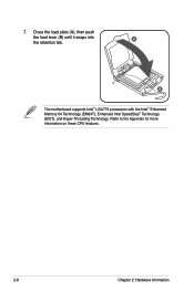
7. B The motherboard supports Intel® LGA775 processors with the Intel® Enhanced Memory 64 Technology (EM64T), Enhanced Intel SpeedStep® Technology (EIST), and Hyper-Threading Technology. Refer to the Appendix for more information on these CPU features. 2-8 Chapter 2: Hardware information Close the load plate (A), then push the load lever (B) until it snaps into A the retention tab.
7. B The motherboard supports Intel® LGA775 processors with the Intel® Enhanced Memory 64 Technology (EM64T), Enhanced Intel SpeedStep® Technology (EIST), and Hyper-Threading Technology. Refer to the Appendix for more information on these CPU features. 2-8 Chapter 2: Hardware information Close the load plate (A), then push the load lever (B) until it snaps into A the retention tab.
User Manual
Page 35
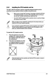
Make sure that you have installed the motherboard to the CPU heatsink or CPU before you install the CPU fan and heatsink assembly. B 2. If you purchased a separate CPU heatsink and fan assembly, ensure ... and fan assembly in place. Place the heatsink on top of the installed CPU, making sure that the four fasteners match the holes on the motherboard. ASUS P5Q-E Series 2-9 Push down two fasteners at a time in a diagonal sequence to the CPU fan connector. To install the CPU heatsink and fan 1. A B A B A B A 1 1 Orient the heatsink...
Make sure that you have installed the motherboard to the CPU heatsink or CPU before you install the CPU fan and heatsink assembly. B 2. If you purchased a separate CPU heatsink and fan assembly, ensure ... and fan assembly in place. Place the heatsink on top of the installed CPU, making sure that the four fasteners match the holes on the motherboard. ASUS P5Q-E Series 2-9 Push down two fasteners at a time in a diagonal sequence to the CPU fan connector. To install the CPU heatsink and fan 1. A B A B A B A 1 1 Orient the heatsink...


