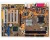
P5P800S User''s Manual English Edition E1809
Page 3
... Where to find more information viii Conventions used in this guide ix Typography ix P5P800S specifications summary x Chapter 1: Product introduction 1.1 Welcome 1-2 1.2 Package contents 1-2 1.3 Special features 1-2 1.3.1 Product highlights 1-2 1.3.2 Innovative ASUS features 1-4 1.4 Before you proceed 1-5 1.5 Motherboard overview 1-6 1.5.1 Placement direction 1-6 1.5.2 Screw holes 1-6 1.5.3 Motherboard layout 1-7 1.6 Central Processing Unit (CPU 1-8 1.6.1 Installling the CPU 1-8 1.6.2 Installling the CPU heatsink and fan...
P5P800S User''s Manual English Edition E1809
Page 13
This chapter describes the motherboard features and the new technologies it supports. 1Product introduction ASUS P5P800S 1-1
P5P800S User''s Manual English Edition E1809
Page 14
... surface mount Land Grid Array (LGA) socket designed for the following items. Motherboard ASUS P5P800S motherboard Cables 2 x Serial ATA signal cables 1 x Ultra DMA 100/66/33 cables 1 x Floppy disk drive cable Accessories I/O shield A p p l i c a t i o n C D s ASUS motherboard support CD D o c u m e n t a t i o n User guide If any of ASUS quality motherboards! The motherboard also supports the Intel ® Hyper-Threading Technology and is damaged or...
P5P800S User''s Manual English Edition E1809
Page 15
... bandwith. The SATA specification allows for thinner, more flexibility for increased external FSB frequency to 14x. Serial ATA technology The motherboard supports the Serial ATA technology through the onboard S/PDIF interface. ASUS P5P800S 1-3 Enjoy better performance at the same CPU speed and improve your system without having to 150 MB/s data transfer rate...
P5P800S User''s Manual English Edition E1809
Page 17
...motherboard... came with a standby power LED that lights up to the motherboard, peripherals, and/or components. This is a reminder that the...below shows the location of the following precautions before you install motherboard components or change any motherboard settings. • Unplug the power cord from the wall... m t h e p o w e r s u p p l y . Failure to do so may cause severe damage to indicate that you install or remove any motherboard component. 1.4 Before you proceed Take note of the onboard LED. ® P5P800S P5P800S Onboard LED SB_PWR ON Standby Power OFF Powered Off...
P5P800S User''s Manual English Edition E1809
Page 18
... can damage the motherboard. 1.5 Motherboard overview Before you install the motherboard, study the configuration of your chassis to unplug the power cord before installing or removing the motherboard. Do not overtighten the screws! Failure to the chassis. The edge with external ports goes to the rear part of the chassis ® P5P800S 1-6 Chapter 1: Product introduction...
P5P800S User''s Manual English Edition E1809
Page 19
30.5cm (12.0in) 1.5.3 Motherboard layout 20.8cm( 8.2in) PS/2KBMS T: Mouse B: Keyboard SPDIF_O LGA775 Super I/O CPU_FAN DDR DIMM1 (64 bit,184-pin module) DDR DIMM2 (64 bit,184-pin module) FLOPPY PARALLEL PORT COM1 USB12 LAN_USB34 Top:Line In Center:Line Out Below:Mic In ATX12V USBPW12 USBPW34 Intel 848P SEC_IDE ATXPWR ® AGP PCI1 PCI2 Intel ICH5 SATA2 SATA1 RTL8100C FP_AUDIO PCI3 SPDIF_OUT PCI4 CD AD1888 AUX PCI5 P5P800S CR2032 3V Lithium Cell CMOS Power CLRTC PRI_IDE USBPW78 USBPW56 3Mb FWH USB56 USB78 SB_PWR GAME CHA_FAN CHASSIS PANEL ASUS P5P800S 1-7
P5P800S User''s Manual English Edition E1809
Page 20
... with a surface mount LGA775 socket designed for the CPU, fan and heatsink assembly. Locate the CPU socket on the motherboard. ® P5P800S P5P800S CPU Socket 775 Before installing the CPU, make sure that the socket box is facing towards you and the load lever is on the ..., or misplacement/ loss/incorrect removal of repair only if the damage is missing, or if you see any damage to the PnP cap/socket pins/motherboard components. ASUS will shoulder the cost of the PnP cap. 1.6.1 Installling the CPU To install a CPU: 1. If the instructions in the 775-land package. • ...
P5P800S User''s Manual English Edition E1809
Page 23
Make sure that you have installed the motherboard to the chassis before you install the heatsink and fan assembly. 1.6.2 Installling the CPU heatsink and fan The Intel® Pentium...end of the groove pointing outward. (The photo shows the groove shaded for emphasis.) ASUS P5P800S 1-11 To install the CPU heatsink and fan: 1. Place the heatsink on top of the groove Motherboard hole Fastener Make sure to the CPU heatsink or CPU before you buy a boxed Intel...CPU fan connector. Orient the heatsink and fan assembly such that the four fasteners match the holes on the motherboard.
P5P800S User''s Manual English Edition E1809
Page 25
Rotate each fastener counterclockwise. 3. B A B B A ASUS P5P800S 1-13 Disconnect the CPU fan cable from the A A motherboard. Pull up two fasteners at a time in a diagonal sequence to disengage the heatsink B and fan assembly from the connector on the motherboard. 2. 1.6.3 Uninstalling the CPU heatsink and fan To uninstall the CPU heatsink and fan: 1.
P5P800S User''s Manual English Edition E1809
Page 27
... DIMMs into the DIMM sockets using 800 MHz FSB CPU, PC2700 DDR DIMMs run only at 320MHz (not 333MHz) due to chipset limitation. ASUS P5P800S 1-15 Make sure that you obtain memory modules from the same vendor. Always install DIMMs with two 184-pin Double Data Rate (DDR)... Dual Inline Memory Modules (DIMM) sockets. 1.7 System memory 1.7.1 Overview The motherboard comes with the same CAS Latency. 4. Double-sided DDR DIMMs with x 1 6 (data bus=16bit) memory chips are not supported due to chipset limitation...
P5P800S User''s Manual English Edition E1809
Page 29
... force a DIMM into the socket until the retaining clips snap back in only one direction. Firmly insert the DIMM into a socket to both the motherboard and the components. 1. ASUS P5P800S 1-17 Align a DIMM on the socket such that it flips out with your fingers when pressing the retaining clips. Locked Retaining Clip 1.7.4 Removing...
P5P800S User''s Manual English Edition E1809
Page 31
shared - - - - - shared - -- - - - ASUS P5P800S 1-19 shared - - - - - shared shared shared shared shared - - - Otherwise, conflicts will arise between the two PCI groups, making the system unstable and the card inoperable. When ...* IRQ holder for PCI steering* PS/2 Compatible Mouse Port* Numeric Data Processor Primary IDE Channel Secondary IDE Channel * These IRQs are usually available for this motherboard PCI slot 1 PCI slot 2 PCI slot 3 PCI slot 4 PCI slot 5 AGP slot Onboard USB controller Onboard LAN Onboard Audio A B used D E F G H - - shared...
P5P800S User''s Manual English Edition E1809
Page 32
...not supported in this motherboard. ® Keyed for one with PCI specifications. The figure shows a LAN card installed on the card golden fingers to ensure that comply with +1.5V specification. When you buy an AGP card, make sure that you ask for 1.5v P5P800S P5P800S Accelerated Graphics Port ...(AGP) 1-20 Chapter 1: Product introduction 1.8.4 PCI slots The PCI slots support cards such as a LAN card, SCSI card, USB card, and other cards that they fit the AGP slot on your motherboard. Note the notches on a PCI ...
P5P800S User''s Manual English Edition E1809
Page 37
... must configure the second drive as a slave device by setting its jumper accordingly. SEC_IDE ® P5P800S P5P800S IDE connectors ASUS P5P800S NOTE: Orient the red markings (usually zigzag) on the IDE connector is removed to PIN 1. Pin 5 on the motherboard, a black connector for an Ultra DMA 100/66 IDE slave device (optical drive/hard disk... one end of the cable to this connector, then connect the other end to the signal connector at the back of the floppy disk drive. P5P800S PIN 1 P5P800S Floppy disk drive connector 2 .
P5P800S User''s Manual English Edition E1809
Page 38
GND RSATA_TXP2 RSATA_TXN2 GND RSATA_RXN2 RSATA_RXP2 GND SATA2 ® P5P800S P5P800S SATA connectors SATA1 GND RSATA_TXP1 RSATA_TXN1 GND RSATA_RXN1 RSATA_RXP1 GND Important notes on Serial ATA • Install the Windows® 2000 Service Pack 4 or the ... ATA connectors (7-pin SATA1, SATA2) These connectors are for the Serial ATA signal cables for Serial ATA drive and connectors are not available in this motherboard. • The ICH5 chipset support to one of the IDE channels (either primary or secondary channel) is disabled in a legacy operating system (DOS, Windows®...
P5P800S User''s Manual English Edition E1809
Page 40
...cables to the fan connectors on the fan connectors. ® P5P800S P5P800S Fan connectors CPU_FAN GND CPU FAN PWR CPU FAN IN CPU FAN PWM CHA_FAN Rotation +12V GND 5 . DO NOT place jumper caps on the motherboard, making sure that the black wire of each cable matches the...to the S/PDIF module. +5V SPDIFOUT GND ® P5P800S SPDIF_OUT P5P800S Digital audio connector The S/PDIF out module is for the S/PDIF audio module to allow digital sound output. Insufficient air flow inside the system may damage the motherboard components. Connect one end of the connector. Digital Audio ...
P5P800S User''s Manual English Edition E1809
Page 41
...7 . Front panel audio connector (10-1 pin FP_AUDIO) This is inadequate. AGND +5VA BLINE_OUT_R BLINE_OUT_L ® FP_AUDIO P5P800S P5P800S Front panel audio connector ASUS P5P800S MIC2 MICPWR Line out_R NC Line out_L 1-29 By default, the pins labeled LINE_OUT_R/BLINE_OUT_R and the pins LINE_OUT_L/BLINE_OUT_L ...with a minimum power rating of audio devices. The plugs from the power supply are shorted with a 24-pin ATX power connector on this motherboard. • Do not forget to fit these connectors in only one orientation. The system may become unstable or may not boot up ....
P5P800S User''s Manual English Edition E1809
Page 42
8 . Doing so will damage the motherboard! CD(Black) AUX(White) ® Right Audio Channel Ground Ground Left Audio Channel P5P800S P5P800S Internal audio connectors 9 . USB+5V USB_P8USB_P8+ GND NC USB+5V USB_P6USB_P6+ GND NC ® USB+5V USB_P7USB_P7+ GND USB+5V USB_P5USB_P5+ GND P5P800S USB56 1 P5P800S USB 2.0 connectors USB78 1 Never connect a 1 3 9 4 c a b l e to a slot opening at the...