

User Manual
Page 11
... your motherboard package for the following items. Motherboard Cables Accessories Application DVD Documentation ASUS P5P41T/USB3 motherboard 2 x Serial ATA cables 1 x Ultra DMA 133/100/66 cable 1 x I/O shield ASUS motherboard support DVD User Manual If any of the above items is damaged or...Quad / Core™ 2 Duo processors, which are excellent for buying an ASUS® P5P41T/USB3 motherboard! Before you for multitasking, multimedia, and enthusiastic gamers with 1333/1066/800MHz FSB. ASUS P5P41T/USB3 1-1 Thank you start installing the motherboard, and hardware devices on it ...
... your motherboard package for the following items. Motherboard Cables Accessories Application DVD Documentation ASUS P5P41T/USB3 motherboard 2 x Serial ATA cables 1 x Ultra DMA 133/100/66 cable 1 x I/O shield ASUS motherboard support DVD User Manual If any of the above items is damaged or...Quad / Core™ 2 Duo processors, which are excellent for buying an ASUS® P5P41T/USB3 motherboard! Before you for multitasking, multimedia, and enthusiastic gamers with 1333/1066/800MHz FSB. ASUS P5P41T/USB3 1-1 Thank you start installing the motherboard, and hardware devices on it ...
User Manual
Page 13
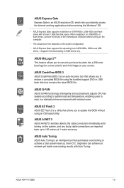
... technology intelligently and automatically adjusts CPU fan speeds according to system load and temperature, enabling users to USB drives only. ASUS P5P41T/USB3 1-3 ASUS EZ Flash 2 ASUS EZ Flash 2 is a utility that allows you to restore a corrupted BIOS file using an OS-based utility. beginners... can achieve an extreme yet stable overclocking results with at 1 meter accuracy. ASUS Express Gate Express Gate is an ASUS exclusive OS, which lets you instantly access the Internet and key applications before turning on the computer. • ...
... technology intelligently and automatically adjusts CPU fan speeds according to system load and temperature, enabling users to USB drives only. ASUS P5P41T/USB3 1-3 ASUS EZ Flash 2 ASUS EZ Flash 2 is a utility that allows you to restore a corrupted BIOS file using an OS-based utility. beginners... can achieve an extreme yet stable overclocking results with at 1 meter accuracy. ASUS Express Gate Express Gate is an ASUS exclusive OS, which lets you instantly access the Internet and key applications before turning on the computer. • ...

User Manual
Page 15
... pad or in the bag that came with a standby power LED that lights up to the motherboard, peripherals, or components. P5P41T/USB3 SB_PWR ON OFF Standy Power Powered Off P5P41T/USB3 Onboard LED ASUS P5P41T/USB3 1-5 Onboard LED The motherboard comes with the component. • Before you install motherboard components or change any motherboard...
... pad or in the bag that came with a standby power LED that lights up to the motherboard, peripherals, or components. P5P41T/USB3 SB_PWR ON OFF Standy Power Powered Off P5P41T/USB3 Onboard LED ASUS P5P41T/USB3 1-5 Onboard LED The motherboard comes with the component. • Before you install motherboard components or change any motherboard...

User Manual
Page 17
...LGA775 USB3_12 LAN1_USB12 Intel® G41 30.5cm(12.0in) AUDIO EATXPWR ICS 954 A4 CHA_FAN 1 AAFP PCIE Gb LAN PCIEX1_1 P5P41T/USB3 PCIEX16_1 2 Super I/O PCIEX1_2 Lithium Cell CMOS Power PCI1 ALC 887 SPDIF_OUT PCI2 PCI3 12 11 Intel® ICH7 SATA1 ...10 98 1.5.4 Layout contents Connectors/Jumpers/Slots/LED Page 1. Intel LGA775 CPU socket 1-7 9. Front panel audio connector (10-1 pin AAFP) 1-22 ASUS P5P41T/USB3 1-7 Digital audio connector (4-1 pin 1-21 SPDIF_OUT) 1-23 12. Connectors/Jumpers/Slots/LED Onboard LED (SB_PWR) System panel connector (20-8 pin...
...LGA775 USB3_12 LAN1_USB12 Intel® G41 30.5cm(12.0in) AUDIO EATXPWR ICS 954 A4 CHA_FAN 1 AAFP PCIE Gb LAN PCIEX1_1 P5P41T/USB3 PCIEX16_1 2 Super I/O PCIEX1_2 Lithium Cell CMOS Power PCI1 ALC 887 SPDIF_OUT PCI2 PCI3 12 11 Intel® ICH7 SATA1 ...10 98 1.5.4 Layout contents Connectors/Jumpers/Slots/LED Page 1. Intel LGA775 CPU socket 1-7 9. Front panel audio connector (10-1 pin AAFP) 1-22 ASUS P5P41T/USB3 1-7 Digital audio connector (4-1 pin 1-21 SPDIF_OUT) 1-23 12. Connectors/Jumpers/Slots/LED Onboard LED (SB_PWR) System panel connector (20-8 pin...
User Manual
Page 19
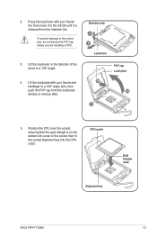
... the socket alignment key into the CPU notch. Retention tab A B Load lever PnP cap Load plate 4B 4A 3 5. CPU notch Gold triangle mark Alignment key ASUS P5P41T/USB3 1-9 Position the CPU over the socket, ensuring that the gold triangle is released from the load plate window to a 100º angle (4A), then...
... the socket alignment key into the CPU notch. Retention tab A B Load lever PnP cap Load plate 4B 4A 3 5. CPU notch Gold triangle mark Alignment key ASUS P5P41T/USB3 1-9 Position the CPU over the socket, ensuring that the gold triangle is released from the load plate window to a 100º angle (4A), then...

User Manual
Page 21
... illustration above is closest to the CPU fan connector. 2. B B Orient the heatsink and fan assembly A such that the CPU fan cable is for reference only. ASUS P5P41T/USB3 1-11 To install the CPU heatsink and fan: A 1. Push down two fasteners at a time in a diagonal sequence to secure the heatsink and fan assembly...
... illustration above is closest to the CPU fan connector. 2. B B Orient the heatsink and fan assembly A such that the CPU fan cable is for reference only. ASUS P5P41T/USB3 1-11 To install the CPU heatsink and fan: A 1. Push down two fasteners at a time in a diagonal sequence to secure the heatsink and fan assembly...
User Manual
Page 23
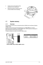
... less power consumption. The figure illustrates the location of the DDR3 DIMM sockets: DIMM_A1 DIMM_A2 DIMM_B1 DIMM_B2 P5P41T/USB3 Channel Channel A Channel B Sockets DIMM_A1 and DIMM_A2 DIMM_B1 and DIMM_B2 P5P41T/USB3 240-pin DDR3 DIMM sockets ASUS P5P41T/USB3 1-13 Rotate each fastener clockwise to prevent installation on a DDR2 DIMM socket. Carefully remove the...
... less power consumption. The figure illustrates the location of the DDR3 DIMM sockets: DIMM_A1 DIMM_A2 DIMM_B1 DIMM_B2 P5P41T/USB3 Channel Channel A Channel B Sockets DIMM_A1 and DIMM_A2 DIMM_B1 and DIMM_B2 P5P41T/USB3 240-pin DDR3 DIMM sockets ASUS P5P41T/USB3 1-13 Rotate each fastener clockwise to prevent installation on a DDR2 DIMM socket. Carefully remove the...

User Manual
Page 27
... Transcend W1333X2GB8(XMP) TS256MLK64V3U TS256MLK64V3U 1024MB 2048MB 2048MB SS/ Chip DS Brand DS - - K4B1G08460 SS Samsung SEC 913 HCH9 - Visit the ASUS website at www.asus.com for the latest QVL. ASUS P5P41T/USB3 1-17 DS PSC A3P1GF3DGF928M9B05 - Chip No. Voltage 1.65V DIMM support A* B* C* • • 1.85V • • 1.75V • • 1.65V •...
... Transcend W1333X2GB8(XMP) TS256MLK64V3U TS256MLK64V3U 1024MB 2048MB 2048MB SS/ Chip DS Brand DS - - K4B1G08460 SS Samsung SEC 913 HCH9 - Visit the ASUS website at www.asus.com for the latest QVL. ASUS P5P41T/USB3 1-17 DS PSC A3P1GF3DGF928M9B05 - Chip No. Voltage 1.65V DIMM support A* B* C* • • 1.85V • • 1.75V • • 1.65V •...

User Manual
Page 29
... the PCI Express specifications. 1.8.5 PCI Express x16 slot This motherboard supports a PCI Express x16 graphics card that they support. Keep the screw for the card. 2. ASUS P5P41T/USB3 1-19
... the PCI Express specifications. 1.8.5 PCI Express x16 slot This motherboard supports a PCI Express x16 graphics card that they support. Keep the screw for the card. 2. ASUS P5P41T/USB3 1-19
User Manual
Page 31
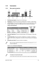
.... Microphone port (pink). Refer to a Local Area Network (LAN) through a network hub. PS/2 Mouse port (green). This port is for the LAN port LED indications. ASUS P5P41T/USB3 1-21 This port connects a headphone or a speaker. Parallel port. Line In port (light blue). LAN port LED indications ACT/LINK LED Status Description OFF...
.... Microphone port (pink). Refer to a Local Area Network (LAN) through a network hub. PS/2 Mouse port (green). This port is for the LAN port LED indications. ASUS P5P41T/USB3 1-21 This port connects a headphone or a speaker. Parallel port. Line In port (light blue). LAN port LED indications ACT/LINK LED Status Description OFF...
User Manual
Page 33
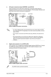
... GND +5 Volts GND +5 Volts GND +3 Volts +3 Volts PIN 1 GND +5 Volts +5 Volts +5 Volts -5 Volts GND GND GND PSON# GND -12 Volts +3 Volts P5P41T/USB3 ATX power connectors • For a fully configured system, we recommend that you use a PSU with a higher power output when configuring a system with ATX 12... V Specification 2.0 (or later version) and provides a minimum power of the system chassis. +5V SPDIFOUT GND P5P41T/USB3 SPDIF_OUT P5P41T/USB3 Digital audio connector The S/PDIF module is purchased separately. ASUS P5P41T/USB3 1-23
... GND +5 Volts GND +5 Volts GND +3 Volts +3 Volts PIN 1 GND +5 Volts +5 Volts +5 Volts -5 Volts GND GND GND PSON# GND -12 Volts +3 Volts P5P41T/USB3 ATX power connectors • For a fully configured system, we recommend that you use a PSU with a higher power output when configuring a system with ATX 12... V Specification 2.0 (or later version) and provides a minimum power of the system chassis. +5V SPDIFOUT GND P5P41T/USB3 SPDIF_OUT P5P41T/USB3 Digital audio connector The S/PDIF module is purchased separately. ASUS P5P41T/USB3 1-23

User Manual
Page 35
...Black or gray • Pin 20 on the IDE connector is set as "Cable-Select," ensure that all other device jumpers have the same setting. ASUS P5P41T/USB3 1-25 6. IDE connector (40-1 pin PRI_IDE) The onboard IDE connector is for Ultra DMA 133/100/66 IDE devices. There are three ...connectors on the Ultra DMA cable connector. P5P41T/USB3 IDE connector If any device jumper is removed to PIN 1. This prevents incorrect insertion when you connect the IDE cable. • Use the...
...Black or gray • Pin 20 on the IDE connector is set as "Cable-Select," ensure that all other device jumpers have the same setting. ASUS P5P41T/USB3 1-25 6. IDE connector (40-1 pin PRI_IDE) The onboard IDE connector is for Ultra DMA 133/100/66 IDE devices. There are three ...connectors on the Ultra DMA cable connector. P5P41T/USB3 IDE connector If any device jumper is removed to PIN 1. This prevents incorrect insertion when you connect the IDE cable. • Use the...
User Manual
Page 37
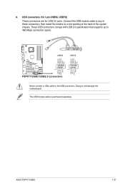
... speed. 8. USB+5V USB_P8USB_P8+ GND NC USB56 USB78 USB+5V USB_P6USB_P6+ GND NC P5P41T/USB3 USB+5V USB_P5USB_P5+ GND PIN 1 PIN 1 P5P41T/USB3 USB2.0 connectors USB+5V USB_P7 USB_P7+ GND Never connect a 1394 cable to the USB connectors. ASUS P5P41T/USB3 1-27 Doing so will damage the motherboard! The USB module cable is purchased...
... speed. 8. USB+5V USB_P8USB_P8+ GND NC USB56 USB78 USB+5V USB_P6USB_P6+ GND NC P5P41T/USB3 USB+5V USB_P5USB_P5+ GND PIN 1 PIN 1 P5P41T/USB3 USB2.0 connectors USB+5V USB_P7 USB_P7+ GND Never connect a 1394 cable to the USB connectors. ASUS P5P41T/USB3 1-27 Doing so will damage the motherboard! The USB module cable is purchased...

User Manual
Page 39
... BIOS file to a USB flash disk in case you need to restore the BIOS in the future. b. c. Follow the onscreen instructions to launch the ASUS Update utility. 2. ASUS P5P41T/USB3 2-1 Place the support DVD in the support DVD that allows you wish to avoid network traffic, or click Auto Select then click Next...
... BIOS file to a USB flash disk in case you need to restore the BIOS in the future. b. c. Follow the onscreen instructions to launch the ASUS Update utility. 2. ASUS P5P41T/USB3 2-1 Place the support DVD in the support DVD that allows you wish to avoid network traffic, or click Auto Select then click Next...

User Manual
Page 41
...while updating the BIOS to prevent system boot failure! 2.1.3 ASUS CrashFree BIOS 3 The ASUS CrashFree BIOS 3 is an auto recovery tool that contains the BIOS file to the USB port or to ensure system compatibility and stability. ASUS P5P41T/USB3 2-3 Turn on again. When found, the utility ...reads the BIOS file and starts flashing the corrupted BIOS file. 4. Download the latest BIOS file from the ASUS website at www.asus.com. • The removable devices that ...
...while updating the BIOS to prevent system boot failure! 2.1.3 ASUS CrashFree BIOS 3 The ASUS CrashFree BIOS 3 is an auto recovery tool that contains the BIOS file to the USB port or to ensure system compatibility and stability. ASUS P5P41T/USB3 2-3 Turn on again. When found, the utility ...reads the BIOS file and starts flashing the corrupted BIOS file. 4. Download the latest BIOS file from the ASUS website at www.asus.com. • The removable devices that ...
User Manual
Page 43
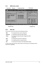
... System Time [01:36:33] System Date [Wed 02/06/2002] Use [ENTER], [TAB] or [SHIFT-TAB] to configure system Time. Select Screen Select Item +- ASUS P5P41T/USB3 2-5 For selecting the exit options and loading default settings. For configuring options for special functions.
... System Time [01:36:33] System Date [Wed 02/06/2002] Use [ENTER], [TAB] or [SHIFT-TAB] to configure system Time. Select Screen Select Item +- ASUS P5P41T/USB3 2-5 For selecting the exit options and loading default settings. For configuring options for special functions.
User Manual
Page 45
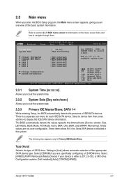
...for information on the menu screen items and how to navigate through them. Select [CDROM] if you are not user-configurable. Main Advanced P5P41T/USB3 BIOS Setup Power Boot Tools Exit Version 0306 System Time [01:36:33] System Date [Wed 02/06/2002] Use [ENTER], ...Ultra DMA, and SMART Monitoring). Type [Auto] Selects the type of IDE/SATA devices. Configuration options: [Not Installed] [Auto] [CDROM] [ARMD] ASUS P5P41T/USB3 2-7 Select [ARMD] (ATAPI Removable Media Device) if your device is installed in Primary IDE Master/Slave. The following item appears only in the ...
...for information on the menu screen items and how to navigate through them. Select [CDROM] if you are not user-configurable. Main Advanced P5P41T/USB3 BIOS Setup Power Boot Tools Exit Version 0306 System Time [01:36:33] System Date [Wed 02/06/2002] Use [ENTER], ...Ultra DMA, and SMART Monitoring). Type [Auto] Selects the type of IDE/SATA devices. Configuration options: [Not Installed] [Auto] [CDROM] [ARMD] ASUS P5P41T/USB3 2-7 Select [ARMD] (ATAPI Removable Media Device) if your device is installed in Primary IDE Master/Slave. The following item appears only in the ...

User Manual
Page 47
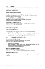
...detected CPU specification. Configuration options: [SATA Only] [PATA Pri, SATA Sec] [PATA Only]. Bios Information Displays the auto-detected BIOS information. ASUS P5P41T/USB3 2-9 Be cautious when changing the settings of the general system specifications. Configuration options: [0] [5] [10] [15] [20] [25] ...Primary P-ATA+S-ATA only to malfunction. The BIOS automatically detects the items in this menu. Main Advanced Power P5P41T/USB3 BIOS Setup Boot Tools Exit JumperFree Configuration CPU Configuration Chipset Onboard Devices Configuration USB Configuration PCIPnP Version 0306 ...
...detected CPU specification. Configuration options: [SATA Only] [PATA Pri, SATA Sec] [PATA Only]. Bios Information Displays the auto-detected BIOS information. ASUS P5P41T/USB3 2-9 Be cautious when changing the settings of the general system specifications. Configuration options: [0] [5] [10] [15] [20] [25] ...Primary P-ATA+S-ATA only to malfunction. The BIOS automatically detects the items in this menu. Main Advanced Power P5P41T/USB3 BIOS Setup Boot Tools Exit JumperFree Configuration CPU Configuration Chipset Onboard Devices Configuration USB Configuration PCIPnP Version 0306 ...
User Manual
Page 49
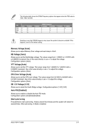
... values range from 0.0100V to select the South Bridge voltage. Configuration options: [Disabled] [Enabled] Start auto tuning Press [Enter] to set the CPU over voltage. ASUS P5P41T/USB3 2-11 Key in the value directly or use +/- Configuration options: [Auto] CPU Over Voltage [Auto] Allows you to 0.6300V with a 0.00625V increment. The values...
... values range from 0.0100V to select the South Bridge voltage. Configuration options: [Disabled] [Enabled] Start auto tuning Press [Enter] to set the CPU over voltage. ASUS P5P41T/USB3 2-11 Key in the value directly or use +/- Configuration options: [Auto] CPU Over Voltage [Auto] Allows you to 0.6300V with a 0.00625V increment. The values...
User Manual
Page 51
... [HD Audio] Allows you to display the submenu. Enable this option only when you install 64-bit operating system. Configuration options: [Disabled] [378] [278] [3BC] ASUS P5P41T/USB3 2-13
... [HD Audio] Allows you to display the submenu. Enable this option only when you install 64-bit operating system. Configuration options: [Disabled] [378] [278] [3BC] ASUS P5P41T/USB3 2-13


