

User Manual
Page 1
P5P41T LE Motherboard
P5P41T LE Motherboard
User Manual
Page 3
Contents Notices...vi Safety information vii About this guide viii P5P41T LE specifications summary ix Chapter 1: Product introduction 1.1 Welcome 1-1 1.2 Package contents 1-1 1.3 Special features 1-1 1.3.1 Product highlights 1-1 1.3.2 Innovative ASUS features 1-2 1.4 Before you proceed 1-4 1.5 Motherboard overview 1-5 1.5.1 Placement direction 1-5 1.5.2 Screw holes 1-5 1.5.3 Motherboard layout 1-6 1.5.4 Layout contents 1-6 1.6 Central Processing Unit (CPU 1-7 1.6.1 Installing the CPU 1-7 1.6.2 Installing the CPU heatsink and fan 1-10...
Contents Notices...vi Safety information vii About this guide viii P5P41T LE specifications summary ix Chapter 1: Product introduction 1.1 Welcome 1-1 1.2 Package contents 1-1 1.3 Special features 1-1 1.3.1 Product highlights 1-1 1.3.2 Innovative ASUS features 1-2 1.4 Before you proceed 1-4 1.5 Motherboard overview 1-5 1.5.1 Placement direction 1-5 1.5.2 Screw holes 1-5 1.5.3 Motherboard layout 1-6 1.5.4 Layout contents 1-6 1.6 Central Processing Unit (CPU 1-7 1.6.1 Installing the CPU 1-7 1.6.2 Installing the CPU heatsink and fan 1-10...
User Manual
Page 6
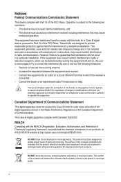
... complies with the REACH (Registration, Evaluation, Authorisation, and Restriction of Chemicals) regulatory framework, we published the chemical substances in our products at ASUS REACH website at http://green.asus.com/english/REACH.htm. However, there is encouraged to try to provide reasonable protection against harmful interference in a residential installation. DO NOT throw...
... complies with the REACH (Registration, Evaluation, Authorisation, and Restriction of Chemicals) regulatory framework, we published the chemical substances in our products at ASUS REACH website at http://green.asus.com/english/REACH.htm. However, there is encouraged to try to provide reasonable protection against harmful interference in a residential installation. DO NOT throw...

User Manual
Page 7
... assistance before using the product, ensure that the power cables for the devices are unplugged before the signal cables are connected. This motherboard should only be included in your regular household waste. Safety information Electrical safety • To prevent electric shock hazard, disconnect the ... extremes. Take it to fix it by yourself. If you add a device. • Before connecting or removing signal cables from the motherboard, ensure that your retailer. • The optical S/PDIF is an optional component (may or may not be used in environments with ambient...
... assistance before using the product, ensure that the power cables for the devices are unplugged before the signal cables are connected. This motherboard should only be included in your regular household waste. Safety information Electrical safety • To prevent electric shock hazard, disconnect the ... extremes. Take it to fix it by yourself. If you add a device. • Before connecting or removing signal cables from the motherboard, ensure that your retailer. • The optical S/PDIF is an optional component (may or may not be used in environments with ambient...
User Manual
Page 8
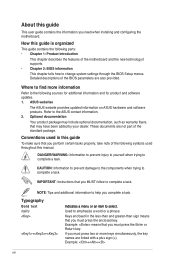
...Product introduction This chapter describes the features of the standard package. ASUS websites The ASUS website provides updated information on ASUS hardware and software products. CAUTION: Information to prevent damage to the...complete a task. Where to find more keys simultaneously, the key names are linked with a plus sign (+). About this guide To make sure that may have been added by your dealer. How... this manual. Detailed descriptions of the BIOS parameters are not part of the motherboard and the new technology it �e�m�t�o�s�e�le&#...
...Product introduction This chapter describes the features of the standard package. ASUS websites The ASUS website provides updated information on ASUS hardware and software products. CAUTION: Information to prevent damage to the...complete a task. Where to find more keys simultaneously, the key names are linked with a plus sign (+). About this guide To make sure that may have been added by your dealer. How... this manual. Detailed descriptions of the BIOS parameters are not part of the motherboard and the new technology it �e�m�t�o�s�e�le&#...

User Manual
Page 11
... package with 1333/ 1066/ 800 MHz FSB. Before you for the following items. Motherboard Cables Accessories Application DVD Documentation ASUS P5P41T LE motherboard 2 x Serial ATA cables 1 x Ultra DMA 100/66/33 cable 1 x I/O shield ASUS motherboard support DVD User Manual 1.3 1.3.1 If any of ASUS quality motherboards! ASUS P5P41T LE 1-1 Special features Product highlights Intel® Core™2 Extreme / Core™2 Quad...
... package with 1333/ 1066/ 800 MHz FSB. Before you for the following items. Motherboard Cables Accessories Application DVD Documentation ASUS P5P41T LE motherboard 2 x Serial ATA cables 1 x Ultra DMA 100/66/33 cable 1 x I/O shield ASUS motherboard support DVD User Manual 1.3 1.3.1 If any of ASUS quality motherboards! ASUS P5P41T LE 1-1 Special features Product highlights Intel® Core™2 Extreme / Core™2 Quad...

User Manual
Page 12
... ACPI management function to turn the PC power button into the motherboard. Five seconds after bootup, you easy setup, Turbo Key boosts performances without entering the Windows OS. Gigabit LAN solution The onboard LAN controller is enhanced with minimal noise. ASUS Q-FAN ASUS Q-FAN technology intelligently and automatically adjusts CPU fan speed according...
... ACPI management function to turn the PC power button into the motherboard. Five seconds after bootup, you easy setup, Turbo Key boosts performances without entering the Windows OS. Gigabit LAN solution The onboard LAN controller is enhanced with minimal noise. ASUS Q-FAN ASUS Q-FAN technology intelligently and automatically adjusts CPU fan speed according...

User Manual
Page 13
... boot logo for Express Gate source codes. ASUS P5P41T LE 1-3 ASUS MyLogo2™ This feature allows you to open the system chassis and clear the RTC data. ASUS CrashFree BIOS 3 ASUS CrashFree BIOS 3 is subject to turn off...reboot the system. eliminates the need to restore a corrupted BIOS file using an OS-based utility. C.P.R. • ASUS Express Gate supports file uploading from SATA HDDs, ODDs, and USB drives. C.P.R. (CPU Parameter Recall) The BIOS ... the CPU parameters to their default settings. Green ASUS This motherboard and its packaging comply with the OpenGL standard.
... boot logo for Express Gate source codes. ASUS P5P41T LE 1-3 ASUS MyLogo2™ This feature allows you to open the system chassis and clear the RTC data. ASUS CrashFree BIOS 3 ASUS CrashFree BIOS 3 is subject to turn off...reboot the system. eliminates the need to restore a corrupted BIOS file using an OS-based utility. C.P.R. • ASUS Express Gate supports file uploading from SATA HDDs, ODDs, and USB drives. C.P.R. (CPU Parameter Recall) The BIOS ... the CPU parameters to their default settings. Green ASUS This motherboard and its packaging comply with the OpenGL standard.
User Manual
Page 14
...case, to avoid damaging them due to static electricity. • Hold components by the edges to the motherboard, peripherals, or components. This is ON, in sleep mode, or in any motherboard settings. • Unplug the power cord from the power supply. Failure to do so may cause ...severe damage to avoid touching the ICs on them. • Whenever you uninstall any component, place it on a grounded antistatic pad or in the bag that the ATX power supply is switched off mode. P5P41T...
...case, to avoid damaging them due to static electricity. • Hold components by the edges to the motherboard, peripherals, or components. This is ON, in sleep mode, or in any motherboard settings. • Unplug the power cord from the power supply. Failure to do so may cause ...severe damage to avoid touching the ICs on them. • Whenever you uninstall any component, place it on a grounded antistatic pad or in the bag that the ATX power supply is switched off mode. P5P41T...
User Manual
Page 15
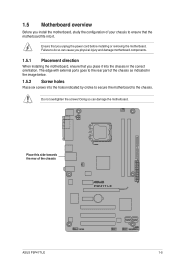
... or removing the motherboard. Doing so can cause you physical injury and damage motherboard components. 1.5.1 Placement direction When installing the motherboard, ensure that the motherboard fits into it. Failure to do so can damage the motherboard. Place this side... towards the rear of the chassis as indicated in the correct orientation. 1.5 Motherboard overview Before you install the motherboard, study the configuration of your chassis to the chassis. The edge with external ports goes to the rear part of the chassis P5P41T LE ASUS P5P41T...
... or removing the motherboard. Doing so can cause you physical injury and damage motherboard components. 1.5.1 Placement direction When installing the motherboard, ensure that the motherboard fits into it. Failure to do so can damage the motherboard. Place this side... towards the rear of the chassis as indicated in the correct orientation. 1.5 Motherboard overview Before you install the motherboard, study the configuration of your chassis to the chassis. The edge with external ports goes to the rear part of the chassis P5P41T LE ASUS P5P41T...
User Manual
Page 16
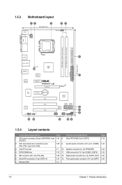
...and chassis fan connectors (4-pin CPU_FAN, 3-pin CHA_FAN) 1-20 9. Intel CPU socket 1-7 10. Digital audio connector (4-1 pin SPDIF_OUT) 1-20 6. 1.5.3 Motherboard layout KBMS 12 3 18.3cm(7.2in) 24 CPU_FAN ATX12V COM1 LPT DDR3 DIMM_A1 (64bit, 240-pin module) DDR3 DIMM_B1 (64bit, 240-pin module) USB34... LGA775 PRI_IDE 5 30.5cm(12.0in) LAN1_USB12 CHA_FAN Intel® G41 AUDIO ICS 9LRS954 1 EATXPWR ATHEROS AR8121 PCIEX1_1 P5P41T LE PCIEX16_1 Super I/O PCIEX1_2 Lithium Cell CMOS Power ALC 662 AAFP SPDIF_OUT 13 12 PCI1 PCI2 PCI3 Intel® ICH7 SATA1 SATA2...
...and chassis fan connectors (4-pin CPU_FAN, 3-pin CHA_FAN) 1-20 9. Intel CPU socket 1-7 10. Digital audio connector (4-1 pin SPDIF_OUT) 1-20 6. 1.5.3 Motherboard layout KBMS 12 3 18.3cm(7.2in) 24 CPU_FAN ATX12V COM1 LPT DDR3 DIMM_A1 (64bit, 240-pin module) DDR3 DIMM_B1 (64bit, 240-pin module) USB34... LGA775 PRI_IDE 5 30.5cm(12.0in) LAN1_USB12 CHA_FAN Intel® G41 AUDIO ICS 9LRS954 1 EATXPWR ATHEROS AR8121 PCIEX1_1 P5P41T LE PCIEX16_1 Super I/O PCIEX1_2 Lithium Cell CMOS Power ALC 662 AAFP SPDIF_OUT 13 12 PCI1 PCI2 PCI3 Intel® ICH7 SATA1 SATA2...
User Manual
Page 17
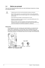
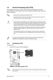
... warranty does not cover damage to ensure system stability. • Upon purchase of the motherboard, ensure that the cam box is shipment/transit-related. • Keep the cap after installing the motherboard. ASUS P5P41T LE 1-7 1.6 Central Processing Unit (CPU) The motherboard comes with a surface mount LGA775 socket designed for the Intel® Core™2 Extreme...
... warranty does not cover damage to ensure system stability. • Upon purchase of the motherboard, ensure that the cam box is shipment/transit-related. • Keep the cap after installing the motherboard. ASUS P5P41T LE 1-7 1.6 Central Processing Unit (CPU) The motherboard comes with a surface mount LGA775 socket designed for the Intel® Core™2 Extreme...
User Manual
Page 20
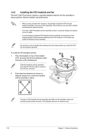
To install the CPU heatsink and fan: 1. Push down two fasteners at a time in place. Place the heatsink on the motherboard. 1.6.2 Installing the CPU heatsink and fan The Intel® LGA775 processor requires a specially designed heatsink and fan assembly to ensure optimum thermal ... of CPU heatsink and fan assembly may differ, but the installation steps and functions should remain the same. Ensure that you have installed the motherboard to secure the heatsink and fan assembly in a diagonal sequence to the chassis before you buy a boxed Intel® processor, the package ...
To install the CPU heatsink and fan: 1. Push down two fasteners at a time in place. Place the heatsink on the motherboard. 1.6.2 Installing the CPU heatsink and fan The Intel® LGA775 processor requires a specially designed heatsink and fan assembly to ensure optimum thermal ... of CPU heatsink and fan assembly may differ, but the installation steps and functions should remain the same. Ensure that you have installed the motherboard to secure the heatsink and fan assembly in a diagonal sequence to the chassis before you buy a boxed Intel® processor, the package ...

User Manual
Page 21
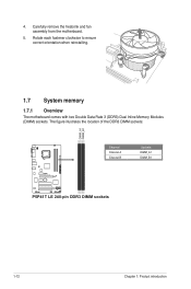
3. Hardware monitoring errors can occur if you fail to disengage the heatsink and fan assembly from the connector on the motherboard labeled CPU_FAN. Pull up two fasteners at a time in a diagonal sequence to plug this connector. 1.6.3 Uninstalling the CPU ...fan cable to connect the CPU fan connector! CPU_FAN CPU FAN PWM CPU FAN IN CPU FAN PWR GND P5P41T LE P5P41T LE CPU fan connector Do not forget to the connector on the motherboard. 2. Rotate each fastener counterclockwise. 3. Disconnect the CPU fan cable from the motherboard. A B A B B A B A ASUS P5P41T LE 1-11
3. Hardware monitoring errors can occur if you fail to disengage the heatsink and fan assembly from the connector on the motherboard labeled CPU_FAN. Pull up two fasteners at a time in a diagonal sequence to plug this connector. 1.6.3 Uninstalling the CPU ...fan cable to connect the CPU fan connector! CPU_FAN CPU FAN PWM CPU FAN IN CPU FAN PWR GND P5P41T LE P5P41T LE CPU fan connector Do not forget to the connector on the motherboard. 2. Rotate each fastener counterclockwise. 3. Disconnect the CPU fan cable from the motherboard. A B A B B A B A ASUS P5P41T LE 1-11
User Manual
Page 22
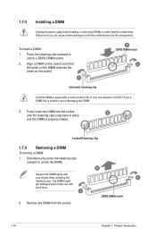
The figure illustrates the location of the DDR3 DIMM sockets: DIMM_A1 DIMM_B1 P5P41T LE Channel Channel A Channel B Sockets DIMM_A1 DIMM_B1 P5P41T LE 240-pin DDR3 DIMM sockets 1-12 Chapter 1: Product introduction Carefully remove the heatsink and fan assembly from the motherboard. 5. Rotate each fastener clockwise to ensure correct orientation when reinstalling. 1.7 System memory 1.7.1 Overview The motherboard comes with two Double Data Rate 3 (DDR3) Dual Inline Memory Modules (DIMM) sockets. 4.
The figure illustrates the location of the DDR3 DIMM sockets: DIMM_A1 DIMM_B1 P5P41T LE Channel Channel A Channel B Sockets DIMM_A1 DIMM_B1 P5P41T LE 240-pin DDR3 DIMM sockets 1-12 Chapter 1: Product introduction Carefully remove the heatsink and fan assembly from the motherboard. 5. Rotate each fastener clockwise to ensure correct orientation when reinstalling. 1.7 System memory 1.7.1 Overview The motherboard comes with two Double Data Rate 3 (DDR3) Dual Inline Memory Modules (DIMM) sockets. 4.

User Manual
Page 23
...65533;i�nd�o�w��s® OS when you want to install 4GB or more memory on the motherboard. • This motherboard does not support DIMMs made up of 256 megabits (Mb) chips or less. • The default memory operation...P5P41T LE Motherboard Qualified Vendors Lists (QVL) DDR3-1333 MHz capability Vendor Part No. For effective use a more memory on the next page) Timing DIMM (BIOS) 8-8-8-24 8-8-8-24 9 9 9-9-9-24 9 9 6-6-6-20 9 9 6-6-6-20 6-6-6-20 7-7-7-24 9 Voltage 1.65-1.85V 1.65-1.85V 1.60V 1.5V 1.8V 1.8V 1.8V 1.65V DIMM Support A* B ASUS P5P41T...
...65533;i�nd�o�w��s® OS when you want to install 4GB or more memory on the motherboard. • This motherboard does not support DIMMs made up of 256 megabits (Mb) chips or less. • The default memory operation...P5P41T LE Motherboard Qualified Vendors Lists (QVL) DDR3-1333 MHz capability Vendor Part No. For effective use a more memory on the next page) Timing DIMM (BIOS) 8-8-8-24 8-8-8-24 9 9 9-9-9-24 9 9 6-6-6-20 9 9 6-6-6-20 6-6-6-20 7-7-7-24 9 Voltage 1.65-1.85V 1.65-1.85V 1.60V 1.5V 1.8V 1.8V 1.8V 1.65V DIMM Support A* B ASUS P5P41T...
User Manual
Page 26
... force. 1 2. 1.7.3 Installing a DIMM Unplug the power supply before adding or removing DIMMs or other system components. Firmly insert the DIMM into a socket to both the motherboard and the components.
... force. 1 2. 1.7.3 Installing a DIMM Unplug the power supply before adding or removing DIMMs or other system components. Firmly insert the DIMM into a socket to both the motherboard and the components.
User Manual
Page 27
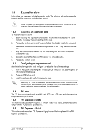
...on the slot. 5. Unplug the power cord before adding or removing expansion cards. Align the card connector with the PCI Express specifications. ASUS P5P41T LE 1-17 Replace the system cover. 1.8.2 Configuring an expansion card After installing the expansion card, configure it and make the necessary ...removed earlier. 6. Keep the screw for the expansion card. Assign an IRQ to use . 4. Remove the system unit cover (if your motherboard is completely seated on shared slots, ensure that the drivers support "Share IRQ" or that they support. Install the software drivers for later ...
...on the slot. 5. Unplug the power cord before adding or removing expansion cards. Align the card connector with the PCI Express specifications. ASUS P5P41T LE 1-17 Replace the system cover. 1.8.2 Configuring an expansion card After installing the expansion card, configure it and make the necessary ...removed earlier. 6. Keep the screw for the expansion card. Assign an IRQ to use . 4. Remove the system unit cover (if your motherboard is completely seated on shared slots, ensure that the drivers support "Share IRQ" or that they support. Install the software drivers for later ...

User Manual
Page 30
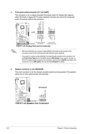
...or a total of the system chassis. +5V SPDIFOUT GND P5P41T LE SPDIF_OUT P5P41T LE Digital audio connector The S/PDIF module is for an additional Sony/Philips Digital Interface (S/PDIF) port. Do not place jumper caps on the motherboard, ensuring that the black wire of each cable matches the ...P5P41T LE fan connectors Only the 4-pin CPU fan connector supports the ASUS Q-FAN feature. 2. Connect the fan cables to the fan connectors. Do not forget to connect the fan cables to the fan connectors on the fan connectors! Insufficient air flow inside the system may damage the motherboard...
...or a total of the system chassis. +5V SPDIFOUT GND P5P41T LE SPDIF_OUT P5P41T LE Digital audio connector The S/PDIF module is for an additional Sony/Philips Digital Interface (S/PDIF) port. Do not place jumper caps on the motherboard, ensuring that the black wire of each cable matches the ...P5P41T LE fan connectors Only the 4-pin CPU fan connector supports the ASUS Q-FAN feature. 2. Connect the fan cables to the fan connectors. Do not forget to connect the fan cables to the fan connectors on the fan connectors! Insufficient air flow inside the system may damage the motherboard...
User Manual
Page 32
...you connect a high-definition front panel audio module to this connector to avail of the motherboard's high-definition audio capability. • If you to [AC97]. 5. GND PRESENCE# SENSE1_RETUR SENSE2_RETUR AGND NC NC NC P5P41T LE AAFP PIN 1 PIN 1 MIC2 MICPWR Line out_R NC Line out_L PORT1 L ...PORT1 R PORT2 R SENSE_SEND PORT2 L HD-audio-compliant Legacy AC'97 pin definition compliant definition P5P41T LE Analog front panel connector • We recommend that supports either HD Audio or legacy AC`97 audio standard. Speaker connector (4- Front...
...you connect a high-definition front panel audio module to this connector to avail of the motherboard's high-definition audio capability. • If you to [AC97]. 5. GND PRESENCE# SENSE1_RETUR SENSE2_RETUR AGND NC NC NC P5P41T LE AAFP PIN 1 PIN 1 MIC2 MICPWR Line out_R NC Line out_L PORT1 L ...PORT1 R PORT2 R SENSE_SEND PORT2 L HD-audio-compliant Legacy AC'97 pin definition compliant definition P5P41T LE Analog front panel connector • We recommend that supports either HD Audio or legacy AC`97 audio standard. Speaker connector (4- Front...


