User Guide
Page 27
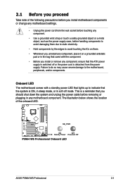
... damaging them due to static electricity. • Hold components by the edges to the motherboard, peripherals, and/or components. 2.1 Before you proceed Take note of the onboard LED. P5N64 WS PRO SB_PWR ON OFF Standy Power Powered Off P5N64 WS Professional Onboard LED ASUS P5N64 WS Professional 2-1 The illustration below shows the location of the following precautions before you install or...
... damaging them due to static electricity. • Hold components by the edges to the motherboard, peripherals, and/or components. 2.1 Before you proceed Take note of the onboard LED. P5N64 WS PRO SB_PWR ON OFF Standy Power Powered Off P5N64 WS Professional Onboard LED ASUS P5N64 WS Professional 2-1 The illustration below shows the location of the following precautions before you install or...

User Guide
Page 28
... the holes indicated by circles to secure the motherboard to the chassis. Failure to do so can damage the motherboard. Place this side towards the rear of the chassis as indicated in the correct orientation. Make sure to the rear part of the chassis P5N64 WS PRO 2-2 Chapter 2: Hardware information The edge with external ports...
... the holes indicated by circles to secure the motherboard to the chassis. Failure to do so can damage the motherboard. Place this side towards the rear of the chassis as indicated in the correct orientation. Make sure to the rear part of the chassis P5N64 WS PRO 2-2 Chapter 2: Hardware information The edge with external ports...

User Guide
Page 29
...240-pin module) DDR3 DIMM_B2 (64bit, 240-pin module) PRI_IDE FLOPPY 2.2.3 Motherboard layout KB_USB56 EATX12V SPDIF_O12 LAN2_USB34 F_ESATA12 LGA775 PWR_FAN EPU CPU_FAN Super I/O LAN1_USB12 AUDIO 88E1116 88E1116 CHA_FAN1 WFG NVIDIA® nForce® 790i(Ultra) SLI™ PCIEX1_1 P5N64 WS PRO PCIEX16_1 88SE6320 VIA VT6308S PCI1 PCIEX16_2 PCI2 Lithium Cell CMOS Power EATXPWR... USB78_EXPRESS_GATE USB910 SB_PWR CLRTC CHASSIS TPM PANEL SAS1 SAS2 Refer to 2.7 Connectors for more information about rear panel connectors and internal connectors. ASUS P5N64 WS Professional 2-3
...240-pin module) DDR3 DIMM_B2 (64bit, 240-pin module) PRI_IDE FLOPPY 2.2.3 Motherboard layout KB_USB56 EATX12V SPDIF_O12 LAN2_USB34 F_ESATA12 LGA775 PWR_FAN EPU CPU_FAN Super I/O LAN1_USB12 AUDIO 88E1116 88E1116 CHA_FAN1 WFG NVIDIA® nForce® 790i(Ultra) SLI™ PCIEX1_1 P5N64 WS PRO PCIEX16_1 88SE6320 VIA VT6308S PCI1 PCIEX16_2 PCI2 Lithium Cell CMOS Power EATXPWR... USB78_EXPRESS_GATE USB910 SB_PWR CLRTC CHASSIS TPM PANEL SAS1 SAS2 Refer to 2.7 Connectors for more information about rear panel connectors and internal connectors. ASUS P5N64 WS Professional 2-3

User Guide
Page 33
... left (B) until it is on the motherboard. To prevent damage to the socket pins, do not remove the PnP cap unless you . ASUS P5N64 WS Professional 2-7 2.3.1 Installing the CPU To install a CPU: 1. Lift the load lever in the direction of the socket box should face you are installing a CPU. 3. P5N64 WS PRO P5N64 WS Professional CPU socket 775 Before installing the...
... left (B) until it is on the motherboard. To prevent damage to the socket pins, do not remove the PnP cap unless you . ASUS P5N64 WS Professional 2-7 2.3.1 Installing the CPU To install a CPU: 1. Lift the load lever in the direction of the socket box should face you are installing a CPU. 3. P5N64 WS PRO P5N64 WS Professional CPU socket 775 Before installing the...

User Guide
Page 36
CPU_FAN CPU_FAN CPU FAN PWM CPU FAN IN CPU FAN PWR GND P5N64 WS PRO P5N64 WS Professional CPU fan connector Do not forget to plug this connector. 2-10 Chapter 2: Hardware information Hardware monitoring errors can occur if you fail to connect the CPU fan connector! B A A A B B B A 3. Connect the CPU fan cable to secure the heatsink and fan assembly in a diagonal sequence to the connector on the motherboard labeled CPU_FAN. 2. Push down two fasteners at a time in place.
CPU_FAN CPU_FAN CPU FAN PWM CPU FAN IN CPU FAN PWR GND P5N64 WS PRO P5N64 WS Professional CPU fan connector Do not forget to plug this connector. 2-10 Chapter 2: Hardware information Hardware monitoring errors can occur if you fail to connect the CPU fan connector! B A A A B B B A 3. Connect the CPU fan cable to secure the heatsink and fan assembly in a diagonal sequence to the connector on the motherboard labeled CPU_FAN. 2. Push down two fasteners at a time in place.
User Guide
Page 39
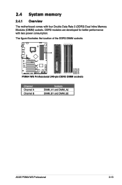
2.4 System memory 2.4.1 Overview The motherboard comes with less power consumption. The figure illustrates the location of the DDR3 DIMM sockets: P5N64 WS PRO DIMM_A1 DIMM_A2 DIMM_B1 DIMM_B2 P5N64 WS Professional 240-pin DDR3 DIMM sockets Channel Channel A Channel B Sockets DIMM_A1 and DIMM_A2 DIMM_B1 and DIMM_B2 ASUS P5N64 WS Professional 2-13 DDR3 modules are developed for better performance with four Double Data Rate 3 (DDR3) Dual Inline Memory Modules (DIMM) sockets.
2.4 System memory 2.4.1 Overview The motherboard comes with less power consumption. The figure illustrates the location of the DDR3 DIMM sockets: P5N64 WS PRO DIMM_A1 DIMM_A2 DIMM_B1 DIMM_B2 P5N64 WS Professional 240-pin DDR3 DIMM sockets Channel Channel A Channel B Sockets DIMM_A1 and DIMM_A2 DIMM_B1 and DIMM_B2 ASUS P5N64 WS Professional 2-13 DDR3 modules are developed for better performance with four Double Data Rate 3 (DDR3) Dual Inline Memory Modules (DIMM) sockets.
User Guide
Page 46
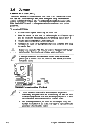
.... The onboard button cell battery powers the RAM data in CMOS. Plug the power cord and turn off is required prior using C.P.R. P5N64 WS PRO CLRTC 12 23 Normal (Default) Clear RTC P5N64 WS Professional Clear RTC RAM • You do not help, remove the onboard battery and move the cap back to pins 1-2. 3. For system...
.... The onboard button cell battery powers the RAM data in CMOS. Plug the power cord and turn off is required prior using C.P.R. P5N64 WS PRO CLRTC 12 23 Normal (Default) Clear RTC P5N64 WS Professional Clear RTC RAM • You do not help, remove the onboard battery and move the cap back to pins 1-2. 3. For system...

User Guide
Page 50
FLOPPY NOTE:Orient the red markings on the connector is for the provided floppy disk drive (FDD) signal cable. Floppy disk drive connector (34-1 pin FLOPPY) This connector is removed to prevent incorrect cable connection when using a FDD cable with a covered Pin 5. 2-24 Chapter 2: Hardware information 2.7.2 Internal connectors 1. P5N64 WS PRO PIN1 P5N64 WS Professional Floppy disk drive connector Pin 5 on the floppy ribbon cable to the signal connector at the back of the cable to this connector, then connect the other end to PIN 1. Insert one end of the floppy disk drive.
FLOPPY NOTE:Orient the red markings on the connector is for the provided floppy disk drive (FDD) signal cable. Floppy disk drive connector (34-1 pin FLOPPY) This connector is removed to prevent incorrect cable connection when using a FDD cable with a covered Pin 5. 2-24 Chapter 2: Hardware information 2.7.2 Internal connectors 1. P5N64 WS PRO PIN1 P5N64 WS Professional Floppy disk drive connector Pin 5 on the floppy ribbon cable to the signal connector at the back of the cable to this connector, then connect the other end to PIN 1. Insert one end of the floppy disk drive.

User Guide
Page 51
...all other device jumpers have the same setting. ASUS P5N64 WS Professional 2-25 If any device jumper is removed to match the covered hole on the IDE ribbon cable to configure your device. 2. P5N64 WS PRO PIN1 P5N64 WS Professional IDE connector Single device Two devices Drive jumper ...setting Cable-Select or Master Cable-Select Master Slave Mode of the following modes to PIN 1. Connect the blue connector to the motherboard's IDE connector, then select...
...all other device jumpers have the same setting. ASUS P5N64 WS Professional 2-25 If any device jumper is removed to match the covered hole on the IDE ribbon cable to configure your device. 2. P5N64 WS PRO PIN1 P5N64 WS Professional IDE connector Single device Two devices Drive jumper ...setting Cable-Select or Master Cable-Select Master Slave Mode of the following modes to PIN 1. Connect the blue connector to the motherboard's IDE connector, then select...
User Guide
Page 52
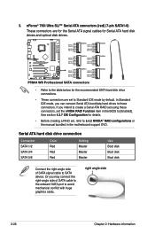
...P5N64 WS PRO GND RSATA_TXP3 RSATA_TXN3 GND RSATA_RXP3 RSATA_RXN3 GND SATA3 GND RSATA_TXP4 RSATA_TXN4 GND SATA3 RSATA_RXP4 RSATA_RXN4 GND SATA4 SATA4 GND RSATA_RXN3 RSATA_RXP3 GND RSATA_TXN3 RSATA_TXP3 GND GND RSATA_RXN4 RSATA_RXP4 GND RSATA_TXN4 RSATA_TXP4 GND GND RSATA_TXP1 RSATA_TXN1 GND RSATA_RXP1 RSATA_RXN1 GND P5B SATA Connectors SATA1 GND RSATA_TXP2 RSATA_TXN2 GND RSATA_RXP2 RSATA_RXN2 GND P5N64 WS Professional...; 790i Ultra SLI™ Serial ATA connectors [red] (7-pin SATA1-6) These connectors are set the nVIDIA RAID Function item in the motherboard support DVD.
...P5N64 WS PRO GND RSATA_TXP3 RSATA_TXN3 GND RSATA_RXP3 RSATA_RXN3 GND SATA3 GND RSATA_TXP4 RSATA_TXN4 GND SATA3 RSATA_RXP4 RSATA_RXN4 GND SATA4 SATA4 GND RSATA_RXN3 RSATA_RXP3 GND RSATA_TXN3 RSATA_TXP3 GND GND RSATA_RXN4 RSATA_RXP4 GND RSATA_TXN4 RSATA_TXP4 GND GND RSATA_TXP1 RSATA_TXN1 GND RSATA_RXP1 RSATA_RXN1 GND P5B SATA Connectors SATA1 GND RSATA_TXP2 RSATA_TXN2 GND RSATA_RXP2 RSATA_RXN2 GND P5N64 WS Professional...; 790i Ultra SLI™ Serial ATA connectors [red] (7-pin SATA1-6) These connectors are set the nVIDIA RAID Function item in the motherboard support DVD.

User Guide
Page 53
... manual bundled in the motherboard support DVD. P5N64 WS PRO SAS1 SAS2 GND RSATA_TXP1 RSATA_TXN1 GND RSATA_RXP1 RSATA_RXN1 GND GND RSATA_TXP2 RSATA_TXN2 GND RSATA_RXP2 RSATA_RXN2 GND P5N64 WS Professional SAS connectors • Please install the Marvell® Controller driver before using SAS hard disk drives, make sure that support SAS hard disk drives. ASUS P5N64 WS Professional 2-27 Marvell® 88SE6320...
... manual bundled in the motherboard support DVD. P5N64 WS PRO SAS1 SAS2 GND RSATA_TXP1 RSATA_TXN1 GND RSATA_RXP1 RSATA_RXN1 GND GND RSATA_TXP2 RSATA_TXN2 GND RSATA_RXP2 RSATA_RXN2 GND P5N64 WS Professional SAS connectors • Please install the Marvell® Controller driver before using SAS hard disk drives, make sure that support SAS hard disk drives. ASUS P5N64 WS Professional 2-27 Marvell® 88SE6320...
User Guide
Page 54
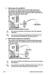
USB+5V USB_P10USB_P10+ GND NC P5N64 WS PRO USB910 PIN 1 USB+5V USB_P9USB_P9+ GND P5N64 WS Professional USB2.0 connector Never connect a 1394 cable to 480 Mbps connection speed. You can connect the USB cable to ASUS Q-Connector (USB, blue) first, and then install the Q-Connector (USB) to the ... cable to ASUS Q-Connector (1394, red) first, and then install the Q-Connector (1394) to a slot opening at the back of the system chassis. Doing so will damage the motherboard! TPA2GND TPB2+12V GND TPA2+ GND TPB2+ +12V P5N64 WS PRO IE1394_2 PIN 1 P5N64 WS Professional IEEE 1394 ...
USB+5V USB_P10USB_P10+ GND NC P5N64 WS PRO USB910 PIN 1 USB+5V USB_P9USB_P9+ GND P5N64 WS Professional USB2.0 connector Never connect a 1394 cable to 480 Mbps connection speed. You can connect the USB cable to ASUS Q-Connector (USB, blue) first, and then install the Q-Connector (USB) to the ... cable to ASUS Q-Connector (1394, red) first, and then install the Q-Connector (1394) to a slot opening at the back of the system chassis. Doing so will damage the motherboard! TPA2GND TPB2+12V GND TPA2+ GND TPB2+ +12V P5N64 WS PRO IE1394_2 PIN 1 P5N64 WS Professional IEEE 1394 ...

User Guide
Page 55
P5N64 WS PRO CD P5N64 WS Professional Internal audio connector 8. Optical drive audio connector (4-pin CD) These connectors allow you to a slot opening at the back of the system chassis. Connect the ... MPEG card. Serial port connector (10-1 pin COM1) This connector is for a serial (COM) port. Left Audio Channel GND GND Right Audio Channel 7. COM1 PIN 1 P5N64 WS PRO P5N64 WS Professional Serial port2(COM1) connector ASUS P5N64 WS Professional 2-29
P5N64 WS PRO CD P5N64 WS Professional Internal audio connector 8. Optical drive audio connector (4-pin CD) These connectors allow you to a slot opening at the back of the system chassis. Connect the ... MPEG card. Serial port connector (10-1 pin COM1) This connector is for a serial (COM) port. Left Audio Channel GND GND Right Audio Channel 7. COM1 PIN 1 P5N64 WS PRO P5N64 WS Professional Serial port2(COM1) connector ASUS P5N64 WS Professional 2-29

User Guide
Page 56
...motherboard components. PWR_FAN CPU_FAN PWR_FAN CPU_FAN CPU FAN PWM CPU FAN IN CPU FAN PWR GND Rotation +12V GND P5N64 WS PRO CHA_FAN1 CHA_FAN2 GND +12V Rotation CHA_FAN1 CHA_FAN2 Rotation +12V GND CHA_FAN3 Rotation +12V GND CHA_FAN3 P5N64 WS Professional Fan connectors Only the CPU-FAN and CHA-FAN 1-2 connectors support the ASUS...Connect the fan cables to use the chassis intrusion detection feature. +5VSB_MB Chassis Signal GND P5N64 WS PRO CHASSIS P5N64 WS Professional Chassis intrusion connector 2-30 Chapter 2: Hardware information The signal is for a chassis-mounted ...
...motherboard components. PWR_FAN CPU_FAN PWR_FAN CPU_FAN CPU FAN PWM CPU FAN IN CPU FAN PWR GND Rotation +12V GND P5N64 WS PRO CHA_FAN1 CHA_FAN2 GND +12V Rotation CHA_FAN1 CHA_FAN2 Rotation +12V GND CHA_FAN3 Rotation +12V GND CHA_FAN3 P5N64 WS Professional Fan connectors Only the CPU-FAN and CHA-FAN 1-2 connectors support the ASUS...Connect the fan cables to use the chassis intrusion detection feature. +5VSB_MB Chassis Signal GND P5N64 WS PRO CHASSIS P5N64 WS Professional Chassis intrusion connector 2-30 Chapter 2: Hardware information The signal is for a chassis-mounted ...

User Guide
Page 57
... Audio standard. P5N64 WS PRO P5N64 WS Professional TPM connector ASUS P5N64 WS Professional 2-31 A TPM system also helps enhance network security, protects digital identities, and ensures platform integrity. TPM connector (20-1 pin TPM) [Optional] This connector supports a Trusted Platform Module (TPM) system, which can securely store keys, digital certificates, passwords, and data. Connect one end of the motherboard's high-definition...
... Audio standard. P5N64 WS PRO P5N64 WS Professional TPM connector ASUS P5N64 WS Professional 2-31 A TPM system also helps enhance network security, protects digital identities, and ensures platform integrity. TPM connector (20-1 pin TPM) [Optional] This connector supports a Trusted Platform Module (TPM) system, which can securely store keys, digital certificates, passwords, and data. Connect one end of the motherboard's high-definition...

User Guide
Page 58
... +12V DC +12V DC +12V DC +12V DC P5N64 WS PRO GND GND GND GND +3 Volts +12 Volts +12 Volts +5V Standby Power OK GND PIN 1 +5 Volts GND +5 Volts GND +3 Volts +3 Volts PIN 1 GND +5 Volts +5 Volts +5 Volts -5 Volts GND GND GND PSON# GND -12 Volts +3 Volts P5N64 WS Professional ATX power connectors • For a fully configured... output is inadequate. • If you use a PSU with 500W to 600W power or above to the Recommended Power Supply Wattage Calculator at http://support.asus.com/PowerSupplyCalculator/PSCalculator.
... +12V DC +12V DC +12V DC +12V DC P5N64 WS PRO GND GND GND GND +3 Volts +12 Volts +12 Volts +5V Standby Power OK GND PIN 1 +5 Volts GND +5 Volts GND +3 Volts +3 Volts PIN 1 GND +5 Volts +5 Volts +5 Volts -5 Volts GND GND GND PSON# GND -12 Volts +3 Volts P5N64 WS Professional ATX power connectors • For a fully configured... output is inadequate. • If you use a PSU with 500W to 600W power or above to the Recommended Power Supply Wattage Calculator at http://support.asus.com/PowerSupplyCalculator/PSCalculator.

User Guide
Page 59
PLED SPEAKER PLED+ PLED+5V Ground Ground Speaker P5N64 WS PRO PANEL PIN 1 IDE_LED+ IDE_LED- The speaker allows you turn on the BIOS settings. Connect the chassis power LED cable to this connector. Connect the HDD ... RESET) This 2-pin connector is for the HDD Activity LED. 14. PWR Ground Reset Ground IDE_LED PWRSW RESET * Requires an ATX power supply P5N64 WS Professional System panel connector • System power LED (2-pin PLED) This 2-pin connector is for the chassis-mounted reset button for the chassis-mounted system warning speaker. ASUS P5N64 WS Professional 2-33
PLED SPEAKER PLED+ PLED+5V Ground Ground Speaker P5N64 WS PRO PANEL PIN 1 IDE_LED+ IDE_LED- The speaker allows you turn on the BIOS settings. Connect the chassis power LED cable to this connector. Connect the HDD ... RESET) This 2-pin connector is for the HDD Activity LED. 14. PWR Ground Reset Ground IDE_LED PWRSW RESET * Requires an ATX power supply P5N64 WS Professional System panel connector • System power LED (2-pin PLED) This 2-pin connector is for the chassis-mounted reset button for the chassis-mounted system warning speaker. ASUS P5N64 WS Professional 2-33

User Guide
Page 61
... 2.8.2 Installing G.P. ASUS P5N64 WS Professional 2-35 Press to avoid electrical shock hazard. 1. Diagnosis card Make sure to the DIMM sockets, align the card connector with the TPM connector and press firmly until the card sits on the motherboard. Reset Button. ...With the LEDs of the diagnosis card facing to turn ON or OFF the computer. 2.8 G.P. Locate the TPM connector (20-1 pin TPM) on the connector completely. Diagnosis card installation 2.8.1 G.P. Diagnosis card layout LED 0 and 1 Power Switch. P5N64 WS PRO P5N64 WS Professional...
... 2.8.2 Installing G.P. ASUS P5N64 WS Professional 2-35 Press to avoid electrical shock hazard. 1. Diagnosis card Make sure to the DIMM sockets, align the card connector with the TPM connector and press firmly until the card sits on the motherboard. Reset Button. ...With the LEDs of the diagnosis card facing to turn ON or OFF the computer. 2.8 G.P. Locate the TPM connector (20-1 pin TPM) on the connector completely. Diagnosis card installation 2.8.1 G.P. Diagnosis card layout LED 0 and 1 Power Switch. P5N64 WS PRO P5N64 WS Professional...

User Guide
Page 73
... to the floppy disk drive or the USB port. ASUSTek EZ Flash 2 BIOS ROM Utility V3.24 FLASH TYPE: SST 49LF080/A LPC Current ROM BOARD: P5N64-WS PRO VER: 0136 DATE: 03/19/2008 Update ROM BOARD: Unknown VER: Unknown DATE: Unknown PATH: A:\ A: C: Note [Enter] Select or Load [Tab] Switch ... Save the BIOS file to download the latest BIOS file for the motherboard. 2. Go to the Tools menu to select EZ Flash 2 and press to enable it is built in the BIOS chip so it . ASUS P5N64 WS Professional 4-5 Visit the ASUS website (www.asus.com) to a floppy disk or a USB flash disk, then ...
... to the floppy disk drive or the USB port. ASUSTek EZ Flash 2 BIOS ROM Utility V3.24 FLASH TYPE: SST 49LF080/A LPC Current ROM BOARD: P5N64-WS PRO VER: 0136 DATE: 03/19/2008 Update ROM BOARD: Unknown VER: Unknown DATE: Unknown PATH: A:\ A: C: Note [Enter] Select or Load [Tab] Switch ... Save the BIOS file to download the latest BIOS file for the motherboard. 2. Go to the Tools menu to select EZ Flash 2 and press to enable it is built in the BIOS chip so it . ASUS P5N64 WS Professional 4-5 Visit the ASUS website (www.asus.com) to a floppy disk or a USB flash disk, then ...

User Guide
Page 102
...arrow key to select between [Ok] or [Cancel], then press to select and update BIOS. Profile AI NET 2 Press ENTER to run ASUS EZ Flash 2. Change Field Enter Go to Sub Screen F1 General Help F10 Save and Exit ESC Exit v02.61 (C)Copyright 1985-2008, American Megatrends... [Enabled] Reset User Data [10] Enter OS Timer [10 Seconds] ASUS O.C. This utility doesn't support : 1.NTFS format Select Screen Select Item +- ASUSTek EZ Flash 2 BIOS ROM Utility V3.24 FLASH TYPE: SST 49LF080/A LPC Current ROM BOARD: P5N64-WS PRO VER: 0136 DATE: 03/19/2008 Update ROM BOARD: Unknown VER: ...
...arrow key to select between [Ok] or [Cancel], then press to select and update BIOS. Profile AI NET 2 Press ENTER to run ASUS EZ Flash 2. Change Field Enter Go to Sub Screen F1 General Help F10 Save and Exit ESC Exit v02.61 (C)Copyright 1985-2008, American Megatrends... [Enabled] Reset User Data [10] Enter OS Timer [10 Seconds] ASUS O.C. This utility doesn't support : 1.NTFS format Select Screen Select Item +- ASUSTek EZ Flash 2 BIOS ROM Utility V3.24 FLASH TYPE: SST 49LF080/A LPC Current ROM BOARD: P5N64-WS PRO VER: 0136 DATE: 03/19/2008 Update ROM BOARD: Unknown VER: ...


