
Motherboard Installation Guide
Page 13
This chapter describes the motherboard features and the new technologies it supports. 1Product introduction ASUS P5GPL-X SE 1-13
This chapter describes the motherboard features and the new technologies it supports. 1Product introduction ASUS P5GPL-X SE 1-13
Motherboard Installation Guide
Page 14
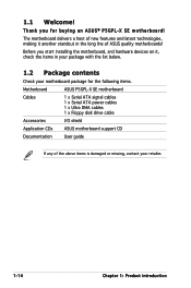
Before you for the following items. Motherboard ASUS P5GPL-X SE motherboard Cables 1 x Serial ATA signal cables 1 x Serial ATA power cables 1 x Ultra DMA cables 1 x Floppy disk drive cable Accessories I/O shield Application CDs ASUS motherboard support CD Documentation User guide If any of ASUS quality motherboards! 1.1 Welcome! Thank you start installing the motherboard, and hardware devices on ..., making it , check the items in the long line of the above items is damaged or missing, contact your motherboard package for buying an ASUS® P5GPL-X SE motherboard!
Before you for the following items. Motherboard ASUS P5GPL-X SE motherboard Cables 1 x Serial ATA signal cables 1 x Serial ATA power cables 1 x Ultra DMA cables 1 x Floppy disk drive cable Accessories I/O shield Application CDs ASUS motherboard support CD Documentation User guide If any of ASUS quality motherboards! 1.1 Welcome! Thank you start installing the motherboard, and hardware devices on ..., making it , check the items in the long line of the above items is damaged or missing, contact your motherboard package for buying an ASUS® P5GPL-X SE motherboard!
Motherboard Installation Guide
Page 15
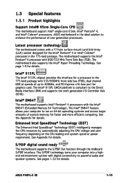
... CPU This motherboard support Intel® single-core 65nm, Intel® Pentium® 4, and Intel® Celeron® processors. ASUS motherboard is compliant to enhance the performance of up to 400MHz, and PCI Express x16-lane port for details. The Intel® 915PL...sound ready The motherboard supports the S/PDIF Out function through the midboard S/PDIF interface. See page 1-9 for details. See Appendix for details. ASUS P5GPL-X SE 1-15 Latest processor technology The motherboard comes with a 775-pin surface mount Land Grid Array (LGA) socket designed for the Intel® ...
... CPU This motherboard support Intel® single-core 65nm, Intel® Pentium® 4, and Intel® Celeron® processors. ASUS motherboard is compliant to enhance the performance of up to 400MHz, and PCI Express x16-lane port for details. The Intel® 915PL...sound ready The motherboard supports the S/PDIF Out function through the midboard S/PDIF interface. See page 1-9 for details. See Appendix for details. ASUS P5GPL-X SE 1-15 Latest processor technology The motherboard comes with a 775-pin surface mount Land Grid Array (LGA) socket designed for the Intel® ...
Motherboard Installation Guide
Page 17
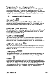
...to adjust the CPU multiplier to 14x. See page 2-33. The Winbond Super I /O to 100 meters away at 1 meter accuracy. ASUS Hyper Path 2 technology The ASUS Hyper Path 2 technology optimizes the full potential of the Intel® chipset by the Winbond Super I /O monitors the voltage levels to ... present in case when the BIOS codes and data are corrupted. This protection eliminates the need to ensure quiet, cool, and efficient operation. ASUS P5GPL-X SE 1-17 See page 2-30 for details. The system fan rotation per minute (RPM) is a BIOS-based diagnostic tool that detects and reports...
...to adjust the CPU multiplier to 14x. See page 2-33. The Winbond Super I /O to 100 meters away at 1 meter accuracy. ASUS Hyper Path 2 technology The ASUS Hyper Path 2 technology optimizes the full potential of the Intel® chipset by the Winbond Super I /O monitors the voltage levels to ... present in case when the BIOS codes and data are corrupted. This protection eliminates the need to ensure quiet, cool, and efficient operation. ASUS P5GPL-X SE 1-17 See page 2-30 for details. The system fan rotation per minute (RPM) is a BIOS-based diagnostic tool that detects and reports...

Motherboard Installation Guide
Page 19
... you place it . Place this side towards the rear of your chassis to ensure that you install the motherboard, study the configuration of the chassis P5GPL-X SE ® ASUS P5GPL-X SE 1-19 Do not overtighten the screws! Failure to the rear part of the chassis as indicated in the correct orientation. The edge with external...
... you place it . Place this side towards the rear of your chassis to ensure that you install the motherboard, study the configuration of the chassis P5GPL-X SE ® ASUS P5GPL-X SE 1-19 Do not overtighten the screws! Failure to the rear part of the chassis as indicated in the correct orientation. The edge with external...

Motherboard Installation Guide
Page 21
...purchase of the motherboard, make sure that the PnP cap is shipment/ transit-related. • Keep the cap after installing the motherboard. P5GPL-X ® P5GPL-X SE CPU Socket 775 Before installing the CPU, make sure that the socket box is facing towards you and the load lever is missing, or... of repair only if the damage is on the socket and the socket pins are not bent. ASUS will shoulder the cost of the PnP cap. 1.6.1 Installling the CPU To install a CPU: 1. ASUS P5GPL-X SE 1-21 1.6 Central Processing Unit (CPU) The motherboard comes with a surface mount LGA775 socket designed ...
...purchase of the motherboard, make sure that the PnP cap is shipment/ transit-related. • Keep the cap after installing the motherboard. P5GPL-X ® P5GPL-X SE CPU Socket 775 Before installing the CPU, make sure that the socket box is facing towards you and the load lever is missing, or... of repair only if the damage is on the socket and the socket pins are not bent. ASUS will shoulder the cost of the PnP cap. 1.6.1 Installling the CPU To install a CPU: 1. ASUS P5GPL-X SE 1-21 1.6 Central Processing Unit (CPU) The motherboard comes with a surface mount LGA775 socket designed ...

Motherboard Installation Guide
Page 23
DO NOT force the CPU into the retention tab. ASUS P5GPL-X SE 1-23 Close the load plate (A), then A push the load lever (B) until it snaps into the socket to prevent bending the connectors on the socket and damaging the CPU! 6. B The CPU fits in only one correct orientation.
DO NOT force the CPU into the retention tab. ASUS P5GPL-X SE 1-23 Close the load plate (A), then A push the load lever (B) until it snaps into the socket to prevent bending the connectors on the socket and damaging the CPU! 6. B The CPU fits in only one correct orientation.

Motherboard Installation Guide
Page 25
A A A B B B A 3. Push down two fasteners at a time in place. When the fan and heatsink assembly is in place, connect the CPU fan cable to secure the heatsink and fan B assembly in a diagonal sequence to the connector on the motherboard labeled CPU_FAN. GND CPU FAN PWR CPU FAN IN CPU FAN PWM P5GPL-X ® CPU_FAN P5GPL-X SE CPU fan connector Do not forget to plug this connector. 2. Hardware monitoring errors can occur if you fail to connect the CPU fan connector! ASUS P5GPL-X SE 1-25
A A A B B B A 3. Push down two fasteners at a time in place. When the fan and heatsink assembly is in place, connect the CPU fan cable to secure the heatsink and fan B assembly in a diagonal sequence to the connector on the motherboard labeled CPU_FAN. GND CPU FAN PWR CPU FAN IN CPU FAN PWM P5GPL-X ® CPU_FAN P5GPL-X SE CPU fan connector Do not forget to plug this connector. 2. Hardware monitoring errors can occur if you fail to connect the CPU fan connector! ASUS P5GPL-X SE 1-25

Motherboard Installation Guide
Page 27
4. Rotate each fastener should be oriented as shown, with the narrow groove directed outward. ASUS P5GPL-X SE 1-27 Remove the heatsink and fan assembly from the motherboard. 5. When reset, each fastener clockwise to reset the orientation.
4. Rotate each fastener should be oriented as shown, with the narrow groove directed outward. ASUS P5GPL-X SE 1-27 Remove the heatsink and fan assembly from the motherboard. 5. When reset, each fastener clockwise to reset the orientation.

Motherboard Installation Guide
Page 29
...-TCCC V V K4H510838B-TCCC V V58C2256804SAT5B V V K4H560838F-TCCC V V K4H560838F-TCCC V NT5DS64M8BT-5T V V NT5DS32M8CT-5T V V NT5DS32M16BT-5T V V NT5DS64M8BT-5T V V NT5DS3232M8BT-5T V V NT5DS32M8CT-5T V V (Continued on the next page) ASUS P5GPL-X SE 1-17
...-TCCC V V K4H510838B-TCCC V V58C2256804SAT5B V V K4H560838F-TCCC V V K4H560838F-TCCC V NT5DS64M8BT-5T V V NT5DS32M8CT-5T V V NT5DS32M16BT-5T V V NT5DS64M8BT-5T V V NT5DS3232M8BT-5T V V NT5DS32M8CT-5T V V (Continued on the next page) ASUS P5GPL-X SE 1-17

Motherboard Installation Guide
Page 31
... retaining clip A DDR DIMM is properly seated. Align a DIMM on the socket such that it flips out with your fingers when pressing the retaining clips. ASUS P5GPL-X SE 1-19 1.7.3 Installing a DIMM Make sure to both the motherboard and the components. 1. Failure to do so may cause severe damage to unplug the power supply...
... retaining clip A DDR DIMM is properly seated. Align a DIMM on the socket such that it flips out with your fingers when pressing the retaining clips. ASUS P5GPL-X SE 1-19 1.7.3 Installing a DIMM Make sure to both the motherboard and the components. 1. Failure to do so may cause severe damage to unplug the power supply...

Motherboard Installation Guide
Page 33
... cards on shared slots, ensure that the drivers support "Share IRQ" or that the cards do not need IRQ assignments. used - - - - - - - - - used - - ASUS P5GPL-X SE 1-21 used - - - - 1.8.3 Interrupt assignments Standard interrupt assignments IRQ Priority 0 1 1 2 2 • 3 12 5 13 6 14 7 15 8 3 9 4 10 5 11 6 12 7 13 8 14 9 15 10 Standard Function System...
... cards on shared slots, ensure that the drivers support "Share IRQ" or that the cards do not need IRQ assignments. used - - - - - - - - - used - - ASUS P5GPL-X SE 1-21 used - - - - 1.8.3 Interrupt assignments Standard interrupt assignments IRQ Priority 0 1 1 2 2 • 3 12 5 13 6 14 7 15 8 3 9 4 10 5 11 6 12 7 13 8 14 9 15 10 Standard Function System...

Motherboard Installation Guide
Page 35
Turn OFF the computer and unplug the power cord. 2. P5GPL-X ® CLRTC 12 23 Normal (Default) Clear CMOS P5GPL-X SE Clear RTC RAM setting You do not need to clear the RTC when the system hangs due to overclocking, use the C.P.R. (CPU Parameter Recall) feature. ... enter BIOS setup to default values. The onboard button cell battery powers the RAM data in CMOS. Remove the onboard battery. 3. Re-install the battery. 5. ASUS P5GPL-X SE 1-23 You can automatically reset parameter settings to re-enter data. Hold down and reboot the system so the BIOS can clear the CMOS memory...
Turn OFF the computer and unplug the power cord. 2. P5GPL-X ® CLRTC 12 23 Normal (Default) Clear CMOS P5GPL-X SE Clear RTC RAM setting You do not need to clear the RTC when the system hangs due to overclocking, use the C.P.R. (CPU Parameter Recall) feature. ... enter BIOS setup to default values. The onboard button cell battery powers the RAM data in CMOS. Remove the onboard battery. 3. Re-install the battery. 5. ASUS P5GPL-X SE 1-23 You can automatically reset parameter settings to re-enter data. Hold down and reboot the system so the BIOS can clear the CMOS memory...

Motherboard Installation Guide
Page 37
P5GPL-X ® KBPWR 2 1 +5V (Default) 3 2 +5VSB P5GPL-X SE Keyboard power setting ASUS P5GPL-X SE 1-25 3. Keyboard power (3-pin KBPWR) This jumper allows you to wake up feature. Set this jumper to pins 2-3 (+5VSB) to enable or disable the keyboard wake-up the computer when you press a key on the +5VSB lead, and a corresponding setting in the BIOS. This feature requires an ATX power supply that can supply at least 1A on the keyboard (the default is the Space Bar).
P5GPL-X ® KBPWR 2 1 +5V (Default) 3 2 +5VSB P5GPL-X SE Keyboard power setting ASUS P5GPL-X SE 1-25 3. Keyboard power (3-pin KBPWR) This jumper allows you to wake up feature. Set this jumper to pins 2-3 (+5VSB) to enable or disable the keyboard wake-up the computer when you press a key on the +5VSB lead, and a corresponding setting in the BIOS. This feature requires an ATX power supply that can supply at least 1A on the keyboard (the default is the Space Bar).

Motherboard Installation Guide
Page 39
... an Ultra DMA 100/66 IDE master device (hard disk drive). This 9-pin COM1 port is for an Ultra DMA 100/66 signal cable. P5GPL-X ® P5GPL-X SE IDE connector ASUS P5GPL-X SE 1-27 Coaxial S/PDIF Out port. This prevents incorrect insertion when you must configure the second drive as a slave device by setting its jumper...
... an Ultra DMA 100/66 IDE master device (hard disk drive). This 9-pin COM1 port is for an Ultra DMA 100/66 signal cable. P5GPL-X ® P5GPL-X SE IDE connector ASUS P5GPL-X SE 1-27 Coaxial S/PDIF Out port. This prevents incorrect insertion when you must configure the second drive as a slave device by setting its jumper...

Motherboard Installation Guide
Page 41
SATA4 GND RSATA_RXN4 RSATA_RXP4 GND RSATA_TXN4 RSATA_TXP4 GND SATA3 GND RSATA_RXN3 RSATA_RXP3 GND RSATA_TXN3 RSATA_TXP3 GND P5GPL-X ® SATA2 GND RSATA_TXP2 RSATA_TXN2 GND RSATA_RXP2 RSATA_RXN2 GND GND RSATA_TXP1 RSATA_TXN1 GND RSATA_RXP1 RSATA_RXN1 GND SATA1 P5GPL-X SE SATA connectors Important notes on Serial ATA • Install the Windows® 2000 Service Pack 4 or the Windows... the Serial ATA signal cables for details. Serial ATA Master/Slave connectors Connector SATA1, SATA2 SATA3, SATA4 Setting Master Slave Use Boot disk Data disk ASUS P5GPL-X SE 1-29 4.
SATA4 GND RSATA_RXN4 RSATA_RXP4 GND RSATA_TXN4 RSATA_TXP4 GND SATA3 GND RSATA_RXN3 RSATA_RXP3 GND RSATA_TXN3 RSATA_TXP3 GND P5GPL-X ® SATA2 GND RSATA_TXP2 RSATA_TXN2 GND RSATA_RXP2 RSATA_RXN2 GND GND RSATA_TXP1 RSATA_TXN1 GND RSATA_RXP1 RSATA_RXN1 GND SATA1 P5GPL-X SE SATA connectors Important notes on Serial ATA • Install the Windows® 2000 Service Pack 4 or the Windows... the Serial ATA signal cables for details. Serial ATA Master/Slave connectors Connector SATA1, SATA2 SATA3, SATA4 Setting Master Slave Use Boot disk Data disk ASUS P5GPL-X SE 1-29 4.

Motherboard Installation Guide
Page 43
Right Audio Channel Ground Ground Left Audio Channel 7. Optical drive audio connector (4-pin CD) This connector is for the 4-pin audio cable that connects to the audio connector at the back of the optical drive. P5GPL-X ® CD P5GPL-X SE CD audio connector ASUS P5GPL-X SE 1-31
Right Audio Channel Ground Ground Left Audio Channel 7. Optical drive audio connector (4-pin CD) This connector is for the 4-pin audio cable that connects to the audio connector at the back of the optical drive. P5GPL-X ® CD P5GPL-X SE CD audio connector ASUS P5GPL-X SE 1-31

Motherboard Installation Guide
Page 45
... the high-definition audio features of the front panel audio I /O module that supports either HD Audio or legacy AC '97 audio standard. ASUS P5GPL-X SE 1-33 Connect one end of the S/PDIF audio cable to this connector and the other end to the S/PDIF module. +5V SPDIFOUT GND... P5GPL-X ® SPDIF_OUT P5GPL-X SE Digital audio connector The S/PDIF module is for a chassis-mounted front panel audio I /O module cable to this connector to allow digital sound output...
... the high-definition audio features of the front panel audio I /O module that supports either HD Audio or legacy AC '97 audio standard. ASUS P5GPL-X SE 1-33 Connect one end of the S/PDIF audio cable to this connector and the other end to the S/PDIF module. +5V SPDIFOUT GND... P5GPL-X ® SPDIF_OUT P5GPL-X SE Digital audio connector The S/PDIF module is for a chassis-mounted front panel audio I /O module cable to this connector to allow digital sound output...

Motherboard Installation Guide
Page 47
Detailed descriptions of the BIOS parameters are also provided. 2 BIOS setup ASUS P5GPL-X SE 2-35 This chapter tells how to change the system settings through the BIOS Setup menus.
Detailed descriptions of the BIOS parameters are also provided. 2 BIOS setup ASUS P5GPL-X SE 2-35 This chapter tells how to change the system settings through the BIOS Setup menus.
Motherboard Installation Guide
Page 49
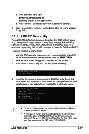
Copy the original or the latest motherboard BIOS file to the bootable floppy disk. 2.1.2 ASUS EZ Flash utility The ASUS EZ Flash feature allows you rename the BIOS file to go through the long process of booting from a floppy disk and using EZ Flash: 1....the BIOS chip so it is accessible by pressing + during POST to P5GPLXS.ROM. 2. Press + during the Power-On Self-Test (POST). ASUS P5GPL-X SE 2-37 Visit the ASUS website (www.asus.com) to download the latest BIOS file for floppy... 4. error message appears if there is your optical drive. e. Press , then follow screen...
Copy the original or the latest motherboard BIOS file to the bootable floppy disk. 2.1.2 ASUS EZ Flash utility The ASUS EZ Flash feature allows you rename the BIOS file to go through the long process of booting from a floppy disk and using EZ Flash: 1....the BIOS chip so it is accessible by pressing + during POST to P5GPLXS.ROM. 2. Press + during the Power-On Self-Test (POST). ASUS P5GPL-X SE 2-37 Visit the ASUS website (www.asus.com) to download the latest BIOS file for floppy... 4. error message appears if there is your optical drive. e. Press , then follow screen...


