User Manual
Page 4
Contents 1.10 Connectors 1-26 1.10.1 Rear panel connectors 1-26 1.10.2 Internal connectors 1-27 Chapter 2: BIOS setup 2.1 Managing and updating your BIOS 2-2 2.1.1 Creating a bootable floppy disk 2-2 2.1.2 ASUS EZ Flash utility 2-3 2.1.3 AFUDOS utility 2-4 2.1.4 ASUS CrashFree BIOS 2 utility 2-6 2.1.5 ASUS Update utility 2-8 2.2 BIOS setup program 2-11 2.2.1 BIOS menu screen 2-12 2.2.2 Menu bar 2-12 2.2.3 Navigation keys 2-12 2.2.4 Menu items 2-13...
Contents 1.10 Connectors 1-26 1.10.1 Rear panel connectors 1-26 1.10.2 Internal connectors 1-27 Chapter 2: BIOS setup 2.1 Managing and updating your BIOS 2-2 2.1.1 Creating a bootable floppy disk 2-2 2.1.2 ASUS EZ Flash utility 2-3 2.1.3 AFUDOS utility 2-4 2.1.4 ASUS CrashFree BIOS 2 utility 2-6 2.1.5 ASUS Update utility 2-8 2.2 BIOS setup program 2-11 2.2.1 BIOS menu screen 2-12 2.2.2 Menu bar 2-12 2.2.3 Navigation keys 2-12 2.2.4 Menu items 2-13...
User Manual
Page 10
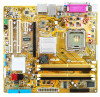
P5GC-VM specifications summary CPU Chipset Front Side Bus Memory VGA Expansion slots Storage Audio LAN USB Rear panel BIOS features LGA775 socket for Intel® Core™2 Duo / Pentium® D / Pentium® 4 /... Celeron® D Processors Compatible with Intel® 06 / 05B / 05A processors Supports Intel® next generation 45nm CPU Supports Intel® Enhanced Intel SpeedStep® Technology (EIST), and Intel® Hyper-Threading Technology * Refer to www.asus...
P5GC-VM specifications summary CPU Chipset Front Side Bus Memory VGA Expansion slots Storage Audio LAN USB Rear panel BIOS features LGA775 socket for Intel® Core™2 Duo / Pentium® D / Pentium® 4 /... Celeron® D Processors Compatible with Intel® 06 / 05B / 05A processors Supports Intel® next generation 45nm CPU Supports Intel® Enhanced Intel SpeedStep® Technology (EIST), and Intel® Hyper-Threading Technology * Refer to www.asus...
User Manual
Page 11
P5GC-VM specifications summary ASUS Special features Manageability Internal connectors Power Requirement Form Factor Support CD contents ASUS EZ Flash ASUS CrashFree BIOS 2 ASUS MyLogo™ ASUS Q-Fan WOL, PXE, RPL, WOR by Ring, PME Wake up 2 x USB 2.0 connectors for 4 ... x 4-pin ATX 12 V power connector 1 x CD audio in connector 1 x Chassis intrusion connector 1 x Front panel high-definition audio connector 1 x S/PDIF out connector 1 x System Panel connector EPS power supply (with 24-pin 12 V plugs) ATX power supply (with 4-pin 12 V plugs) MicroATX ...
P5GC-VM specifications summary ASUS Special features Manageability Internal connectors Power Requirement Form Factor Support CD contents ASUS EZ Flash ASUS CrashFree BIOS 2 ASUS MyLogo™ ASUS Q-Fan WOL, PXE, RPL, WOR by Ring, PME Wake up 2 x USB 2.0 connectors for 4 ... x 4-pin ATX 12 V power connector 1 x CD audio in connector 1 x Chassis intrusion connector 1 x Front panel high-definition audio connector 1 x S/PDIF out connector 1 x System Panel connector EPS power supply (with 24-pin 12 V plugs) ATX power supply (with 4-pin 12 V plugs) MicroATX ...
User Manual
Page 38
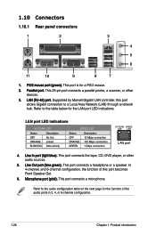
..., or other devices. 3. This 25-pin port connects a parallel printer, a scanner, or other audio sources. 5. LAN (RJ-45) port. Parallel port. 1.10 Connectors 1.10.1 Rear panel connectors 1 2 3 4 5 6 11 10 9 8 7 1. This port connects a microphone.
..., or other devices. 3. This 25-pin port connects a parallel printer, a scanner, or other audio sources. 5. LAN (RJ-45) port. Parallel port. 1.10 Connectors 1.10.1 Rear panel connectors 1 2 3 4 5 6 11 10 9 8 7 1. This port connects a microphone.
User Manual
Page 45
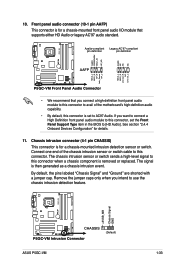
... or switch sends a high-level signal to this connector when a chassis component is removed or replaced. R P5GC-VM +5VSB_MB Chassis Signal GND CHASSIS P5GC-VM Intrusion Connector (Default) ASUS P5GC-VM 1-33 Connect one end of the motherboard's high-definition audio capability. • By default, this connector,... Legacy AC'97-compliant pin definition pin definition R P5GC-VM AGND PRESENSE# MIC2_JD HP_HD AGND NC NC NC AAFP MIC2_L MIC2_R Line out_R NC Line out_L MIC2_L MIC2_R HP_R Jack_Sense HP_L P5GC-VM Front Panel Audio Connector • We recommend that supports either HD...
... or switch sends a high-level signal to this connector when a chassis component is removed or replaced. R P5GC-VM +5VSB_MB Chassis Signal GND CHASSIS P5GC-VM Intrusion Connector (Default) ASUS P5GC-VM 1-33 Connect one end of the motherboard's high-definition audio capability. • By default, this connector,... Legacy AC'97-compliant pin definition pin definition R P5GC-VM AGND PRESENSE# MIC2_JD HP_HD AGND NC NC NC AAFP MIC2_L MIC2_R Line out_R NC Line out_L MIC2_L MIC2_R HP_R Jack_Sense HP_L P5GC-VM Front Panel Audio Connector • We recommend that supports either HD...
User Manual
Page 47
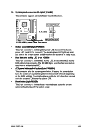
...(20-8 pin F_PANEL) This connector supports several chassis-mounted functions. Connect the HDD Activity LED cable to this connector. ASUS P5GC-VM 1-35 PLED PWRSW F_PANEL HDLED RESET P5GC-VM System Panel Connector • System power LED (2-pin PWRLED) This 2-pin connector is for the HDD Activity LED. Connect the ... Hard disk drive activity LED (2-pin HDLED) This 2-pin connector is for the chassis-mounted reset button for the system power LED. R P5GC-VM PLED+ PLEDPWR GND IDELED+ IDELED- Pressing the power button turns the system on the system power, and blinks when the system is in ...
...(20-8 pin F_PANEL) This connector supports several chassis-mounted functions. Connect the HDD Activity LED cable to this connector. ASUS P5GC-VM 1-35 PLED PWRSW F_PANEL HDLED RESET P5GC-VM System Panel Connector • System power LED (2-pin PWRLED) This 2-pin connector is for the HDD Activity LED. Connect the ... Hard disk drive activity LED (2-pin HDLED) This 2-pin connector is for the chassis-mounted reset button for the system power LED. R P5GC-VM PLED+ PLEDPWR GND IDELED+ IDELED- Pressing the power button turns the system on the system power, and blinks when the system is in ...
User Manual
Page 72
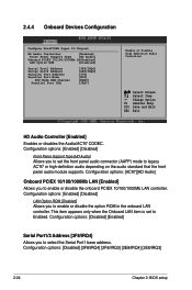
... PCIEX 10/100/1000Mb LAN controller. 2.4.4 Onboard Devices Configuration Configure Win627DHG Super IO Chipset HD Audio Controller [Enabled] Front Panel Support Type [HD Audio] Onboard PCIEX 10/100/1000Mb LA[Enabled] LAN Option ROM [Disabled] Serial Port1 Address Serial ...IRQ3] [378] [ECP] [DMA3] [IRQ7] Enable or Disable High Definition Audio Controller Select Screen Select Item +- Configuration options: [Enabled] [Disabled] Front Panel Support Type [HD Audio] Allows you to Enabled. Configuration options: [Disabled] [3F8/IRQ4] [2F8/IRQ3] [3E8/IRQ4] [2E8/IRQ3] 2-24 Chapter...
... PCIEX 10/100/1000Mb LAN controller. 2.4.4 Onboard Devices Configuration Configure Win627DHG Super IO Chipset HD Audio Controller [Enabled] Front Panel Support Type [HD Audio] Onboard PCIEX 10/100/1000Mb LA[Enabled] LAN Option ROM [Disabled] Serial Port1 Address Serial ...IRQ3] [378] [ECP] [DMA3] [IRQ7] Enable or Disable High Definition Audio Controller Select Screen Select Item +- Configuration options: [Enabled] [Disabled] Front Panel Support Type [HD Audio] Allows you to Enabled. Configuration options: [Disabled] [3F8/IRQ4] [2F8/IRQ3] [3E8/IRQ4] [2E8/IRQ3] 2-24 Chapter...


