
User Manual
Page 1
Motherboard P5G43T-M PRO
Motherboard P5G43T-M PRO

User Manual
Page 3
Contents Notices...vi Safety information vii About this guide viii P5G43T-M PRO specifications summary ix Chapter 1: Product introduction 1.1 Welcome 1-1 1.2 Package contents 1-1 1.3 Special features 1-1 1.3.1 Product highlights 1-1 1.3.2 Innovative ASUS features 1-2 1.4 Before you proceed 1-4 1.5 Motherboard overview 1-5 1.5.1 Placement direction 1-5 1.5.2 Screw holes 1-5 1.5.3 Motherboard layout 1-6 1.5.4 Layout contents 1-6 1.6 Central Processing Unit (CPU 1-7 1.6.1 Installing the CPU 1-7 1.6.2 Installing the CPU heatsink and fan 1-10...
Contents Notices...vi Safety information vii About this guide viii P5G43T-M PRO specifications summary ix Chapter 1: Product introduction 1.1 Welcome 1-1 1.2 Package contents 1-1 1.3 Special features 1-1 1.3.1 Product highlights 1-1 1.3.2 Innovative ASUS features 1-2 1.4 Before you proceed 1-4 1.5 Motherboard overview 1-5 1.5.1 Placement direction 1-5 1.5.2 Screw holes 1-5 1.5.3 Motherboard layout 1-6 1.5.4 Layout contents 1-6 1.6 Central Processing Unit (CPU 1-7 1.6.1 Installing the CPU 1-7 1.6.2 Installing the CPU heatsink and fan 1-10...
User Manual
Page 6
...harmful interference in the Radio Interference Regulations of the Canadian Department of the FCC Rules. If this equipment. DO NOT throw the motherboard in municipal waste. DO NOT throw the mercury-containing button cell battery in municipal waste. These limits are designed to comply ... emissions from that to which can radiate radio frequency energy and, if not installed and used in our products at ASUS REACH website at http://green.asus.com/english/REACH.htm. Changes or modifications to assure compliance with the REACH (Registration, Evaluation, Authorisation, and Restriction...
...harmful interference in the Radio Interference Regulations of the Canadian Department of the FCC Rules. If this equipment. DO NOT throw the motherboard in municipal waste. DO NOT throw the mercury-containing button cell battery in municipal waste. These limits are designed to comply ... emissions from that to which can radiate radio frequency energy and, if not installed and used in our products at ASUS REACH website at http://green.asus.com/english/REACH.htm. Changes or modifications to assure compliance with the REACH (Registration, Evaluation, Authorisation, and Restriction...
User Manual
Page 7
...signal cables are unplugged. • Seek professional assistance before you add a device. • Before connecting or removing signal cables from the motherboard, ensure that all power cables are connected. If possible, disconnect all power cables from connectors, slots, sockets and circuitry. • ... product, ensure that your power supply is an optional component (may or may become wet. Contact a qualified service technician or your motherboard) and is broken, do not try to a hazardous material collection point. • Never replace the battery with your dealer immediately....
...signal cables are unplugged. • Seek professional assistance before you add a device. • Before connecting or removing signal cables from the motherboard, ensure that all power cables are connected. If possible, disconnect all power cables from connectors, slots, sockets and circuitry. • ... product, ensure that your power supply is an optional component (may or may become wet. Contact a qualified service technician or your motherboard) and is broken, do not try to a hazardous material collection point. • Never replace the battery with your dealer immediately....
User Manual
Page 8
...more keys simultaneously, the key names are also provided. DANGER/WARNING: Information to prevent injury to yourself when trying to the ASUS contact information. 2. NOTE: Tips and additional information to complete a task. Example: ++ viii Optional documentation Your product package ...with a plus sign (+). IMPORTANT: Instructions that you MUST follow to help you need when installing and configuring the motherboard. Detailed descriptions of the standard package. Typography Bold text In�d�ic�a�te�s�a�...
...more keys simultaneously, the key names are also provided. DANGER/WARNING: Information to prevent injury to yourself when trying to the ASUS contact information. 2. NOTE: Tips and additional information to complete a task. Example: ++ viii Optional documentation Your product package ...with a plus sign (+). IMPORTANT: Instructions that you MUST follow to help you need when installing and configuring the motherboard. Detailed descriptions of the standard package. Typography Bold text In�d�ic�a�te�s�a�...
User Manual
Page 11
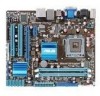
... , check the items in your package with the list below. 1.2 Package contents Check your motherboard package for the following items. Motherboard Cables Accessories Application DVD Documentation ASUS P5G43T-M PRO motherboard 2 x Serial ATA cables 1 x Ultra DMA 133/100/66 cable 1 x I/O shield ASUS motherboard support DVD User Manual If any of the above items is damaged or missing, contact...
... , check the items in your package with the list below. 1.2 Package contents Check your motherboard package for the following items. Motherboard Cables Accessories Application DVD Documentation ASUS P5G43T-M PRO motherboard 2 x Serial ATA cables 1 x Ultra DMA 133/100/66 cable 1 x I/O shield ASUS motherboard support DVD User Manual If any of the above items is damaged or missing, contact...
User Manual
Page 12
... Gate Express Gate is an auto-recovery tool that allows you to convert your favorite photo into the motherboard. ASUS CrashFree BIOS 3 ASUS CrashFree BIOS 3 is a unique OS built into a 256-color boot logo for a more colorful and vivid image on the Serial ATA ...(SATA) 3Gb/s storage specifications, delivering enhanced scalability and doubling the bus bandwidth for advanced operating systems. 1.3.2 Innovative ASUS features ASUS MyLogo2™ This feature allows you to restore a corrupted BIOS file using the bundled support DVD or USB disk that of display outputs...
... Gate Express Gate is an auto-recovery tool that allows you to convert your favorite photo into the motherboard. ASUS CrashFree BIOS 3 ASUS CrashFree BIOS 3 is a unique OS built into a 256-color boot logo for a more colorful and vivid image on the Serial ATA ...(SATA) 3Gb/s storage specifications, delivering enhanced scalability and doubling the bus bandwidth for advanced operating systems. 1.3.2 Innovative ASUS features ASUS MyLogo2™ This feature allows you to restore a corrupted BIOS file using the bundled support DVD or USB disk that of display outputs...
User Manual
Page 13
... the RTC data. eliminates the need to 100 meters at 1 meter accuracy. C.P.R. (CPU Parameter Recall) The BIOS C.P.R. ASUS P5G43T-M PRO 1-3 Refer to overclocking failure. ASUS Anti-Surge Protection This special design prevents expensive devices and the motherboard from damage caused by power surges from SATA HDDs, ODDs, and USB drives. feature automatically restores the...
... the RTC data. eliminates the need to 100 meters at 1 meter accuracy. C.P.R. (CPU Parameter Recall) The BIOS C.P.R. ASUS P5G43T-M PRO 1-3 Refer to overclocking failure. ASUS Anti-Surge Protection This special design prevents expensive devices and the motherboard from damage caused by power surges from SATA HDDs, ODDs, and USB drives. feature automatically restores the...
User Manual
Page 14
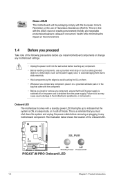
... the power supply. Green ASUS This motherboard and its packaging comply with the component. • Before you must shut down the system and unplug the power cable before removing or plugging in any component, ensure that the system is a reminder that you install or remove any motherboard component. SB_PWR P5G43T-M PRO ON OFF Standby...
... the power supply. Green ASUS This motherboard and its packaging comply with the component. • Before you must shut down the system and unplug the power cable before removing or plugging in any component, ensure that the system is a reminder that you install or remove any motherboard component. SB_PWR P5G43T-M PRO ON OFF Standby...
User Manual
Page 15
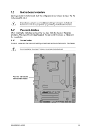
...this side towards the rear of the chassis P5G43T-M PRO ASUS P5G43T-M PRO 1-5 Failure to do so can damage the motherboard. Doing so can cause you physical injury and damage motherboard components. 1.5.1 Placement direction When installing the motherboard, ensure that the motherboard fits into it. Ensure that you place it... 1.5.2 Screw holes Place six screws into the holes indicated by circles to secure the motherboard to ensure that you unplug the power cord before installing or removing the motherboard. The edge with external ports goes to the rear part of the chassis as indicated...
...this side towards the rear of the chassis P5G43T-M PRO ASUS P5G43T-M PRO 1-5 Failure to do so can damage the motherboard. Doing so can cause you physical injury and damage motherboard components. 1.5.1 Placement direction When installing the motherboard, ensure that the motherboard fits into it. Ensure that you place it... 1.5.2 Screw holes Place six screws into the holes indicated by circles to secure the motherboard to ensure that you unplug the power cord before installing or removing the motherboard. The edge with external ports goes to the rear part of the chassis as indicated...
User Manual
Page 17
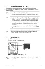
... of repair only if the damage is shipment/transit-related. • Keep the cap after installing the motherboard. ASUS will process Return Merchandise Authorization (RMA) requests only if the motherboard comes with the Intel® Enhanced Intel SpeedStep® Technology (EIST) and Hyper-Threading Technology. 1.6.1 ...cap on your retailer immediately if the PnP cap is missing, or if you and the load lever is on the motherboard. ASUS P5G43T-M PRO 1-7 P5G43T-M PRO P5G43T-M PRO CPU socket 775 Before installing the CPU, ensure that the PnP cap is on the LGA775 socket. •...
... of repair only if the damage is shipment/transit-related. • Keep the cap after installing the motherboard. ASUS will process Return Merchandise Authorization (RMA) requests only if the motherboard comes with the Intel® Enhanced Intel SpeedStep® Technology (EIST) and Hyper-Threading Technology. 1.6.1 ...cap on your retailer immediately if the PnP cap is missing, or if you and the load lever is on the motherboard. ASUS P5G43T-M PRO 1-7 P5G43T-M PRO P5G43T-M PRO CPU socket 775 Before installing the CPU, ensure that the PnP cap is on the LGA775 socket. •...

User Manual
Page 20
... the CPU heatsink and fan: 1. Push down two fasteners at a time in a diagonal sequence to the CPU heatsink or CPU before you have installed the motherboard to the chassis before you buy a CPU separately, ensure that the four fasteners match the holes on the...
... the CPU heatsink and fan: 1. Push down two fasteners at a time in a diagonal sequence to the CPU heatsink or CPU before you have installed the motherboard to the chassis before you buy a CPU separately, ensure that the four fasteners match the holes on the...
User Manual
Page 21
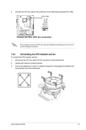
3. Hardware monitoring errors can occur if you fail to disengage the heatsink and fan assembly from the connector on the motherboard labeled CPU_FAN. Pull up two fasteners at a time in a diagonal sequence to plug this connector. 1.6.3 Uninstalling the CPU heatsink ... 1. CPU_FAN GND CPU FAN PWR CPU FAN IN CPU FAN PWM P5G43T-M PRO P5G43T-M PRO CPU fan connector Do not forget to the connector on the motherboard. 2. A B A B B A B A ASUS P5G43T-M PRO 1-11 Disconnect the CPU fan cable from the motherboard. Connect the CPU fan cable to connect the CPU fan connector! ...
3. Hardware monitoring errors can occur if you fail to disengage the heatsink and fan assembly from the connector on the motherboard labeled CPU_FAN. Pull up two fasteners at a time in a diagonal sequence to plug this connector. 1.6.3 Uninstalling the CPU heatsink ... 1. CPU_FAN GND CPU FAN PWR CPU FAN IN CPU FAN PWM P5G43T-M PRO P5G43T-M PRO CPU fan connector Do not forget to the connector on the motherboard. 2. A B A B B A B A ASUS P5G43T-M PRO 1-11 Disconnect the CPU fan cable from the motherboard. Connect the CPU fan cable to connect the CPU fan connector! ...

User Manual
Page 22
Rotate each fastener clockwise to ensure correct orientation when reinstalling. 1.7 System memory 1.7.1 Overview The motherboard comes with two Double Data Rate 3 (DDR3) Dual Inline Memory Modules (DIMM) sockets. The figure illustrates the location of the DDR3 DIMM sockets: DIMM_A1 DIMM_B1 Channel Channel A Channel B Sockets DIMM_A1 DIMM_B1 P5G43T-M PRO P5G43T-M PRO 240-pin DDR3 DIMM sockets 1-12 Chapter 1: Product introduction 4. Carefully remove the heatsink and fan assembly from the motherboard. 5.
Rotate each fastener clockwise to ensure correct orientation when reinstalling. 1.7 System memory 1.7.1 Overview The motherboard comes with two Double Data Rate 3 (DDR3) Dual Inline Memory Modules (DIMM) sockets. The figure illustrates the location of the DDR3 DIMM sockets: DIMM_A1 DIMM_B1 Channel Channel A Channel B Sockets DIMM_A1 DIMM_B1 P5G43T-M PRO P5G43T-M PRO 240-pin DDR3 DIMM sockets 1-12 Chapter 1: Product introduction 4. Carefully remove the heatsink and fan assembly from the motherboard. 5.
User Manual
Page 23
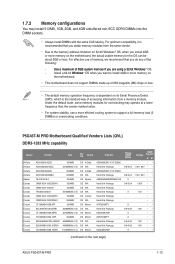
.... • For system stability, use of memory, we recommend that you install 4GB or more memory on the motherboard. • This motherboard does not support DIMMs made up of 256 megabits (Mb) chips or less. • The default memory operation ...P5G43T-M PRO Motherboard Qualified Vendors Lists (QVL) DDR3-1333 MHz capability Vendor A-Data A-Data A-Data A-Data Apacer Corsair Corsair Corsair Corsair Corsair Crucial Crucial Crucial Crucial Crucial Crucial Crucial Part No. For effective use a more efficient cooling system to install 4GB or more memory on the next page) ASUS P5G43T...
.... • For system stability, use of memory, we recommend that you install 4GB or more memory on the motherboard. • This motherboard does not support DIMMs made up of 256 megabits (Mb) chips or less. • The default memory operation ...P5G43T-M PRO Motherboard Qualified Vendors Lists (QVL) DDR3-1333 MHz capability Vendor A-Data A-Data A-Data A-Data Apacer Corsair Corsair Corsair Corsair Corsair Crucial Crucial Crucial Crucial Crucial Crucial Crucial Part No. For effective use a more efficient cooling system to install 4GB or more memory on the next page) ASUS P5G43T...
User Manual
Page 27
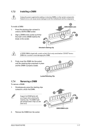
... the retaining clips snap back in only one direction. Press the retaining clips outward to both the motherboard and the components. Simultaneously press the retaining clips outward to avoid damaging the DIMM. 3. Locked Retaining Clip 1.7.4 Removing a DIMM To remove a DIMM: 1. Remove the DIMM from the socket. 2 1 DDR3 DIMM notch ASUS P5G43T-M PRO 1-17
... the retaining clips snap back in only one direction. Press the retaining clips outward to both the motherboard and the components. Simultaneously press the retaining clips outward to avoid damaging the DIMM. 3. Locked Retaining Clip 1.7.4 Removing a DIMM To remove a DIMM: 1. Remove the DIMM from the socket. 2 1 DDR3 DIMM notch ASUS P5G43T-M PRO 1-17
User Manual
Page 28
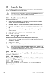
... the expansion cards that complies with the PCI Express specifications. 1-18 Chapter 1: Product introduction Remove the system unit cover (if your motherboard is completely seated on shared slots, ensure that the drivers support "Share IRQ" or that the cards do so may need IRQ assignments... power cord before adding or removing expansion cards. Remove the bracket opposite the slot that came with the screw you physical injury and damage motherboard components. 1.8.1 Installing an expansion card To install an expansion card: 1. Keep the screw for the card. 2. When using PCI cards on...
... the expansion cards that complies with the PCI Express specifications. 1-18 Chapter 1: Product introduction Remove the system unit cover (if your motherboard is completely seated on shared slots, ensure that the drivers support "Share IRQ" or that the cards do so may need IRQ assignments... power cord before adding or removing expansion cards. Remove the bracket opposite the slot that came with the screw you physical injury and damage motherboard components. 1.8.1 Installing an expansion card To install an expansion card: 1. Keep the screw for the card. 2. When using PCI cards on...
User Manual
Page 31
...Bus (USB) ports are available for connecting USB 2.0 devices. 13. DVI-D Out port. Insufficient air flow inside the system may damage the motherboard components. ASUS P5G43T-M PRO 1-21 Connect the fan cables to the fan connectors. USB 2.0 ports 3 and 4. These two 4-pin Universal Serial Bus (USB) ...ports are not jumpers! Do not place jumper caps on the motherboard, ensuring that the black wire of each cable matches the ground pin ...
...Bus (USB) ports are available for connecting USB 2.0 devices. 13. DVI-D Out port. Insufficient air flow inside the system may damage the motherboard components. ASUS P5G43T-M PRO 1-21 Connect the fan cables to the fan connectors. USB 2.0 ports 3 and 4. These two 4-pin Universal Serial Bus (USB) ...ports are not jumpers! Do not place jumper caps on the motherboard, ensuring that the black wire of each cable matches the ground pin ...
User Manual
Page 34
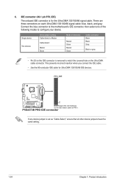
P5G43T-M PRO IDE connector If any device jumper is removed to the motherboard's IDE connector, then select one of device(s) Master Slave Master Slave Cable connector Black Black Gray Black or gray • Pin 20 on the Ultra ... on the IDE connector is set as "Cable-Select," ensure that all other device jumpers have the same setting. 1-24 Chapter 1: Product introduction 6. PRI_IDE PIN1 P5G43T-M PRO NOTE:Orient the red markings on each Ultra DMA 133/100/66 signal cable: blue, black, and gray. There are three connectors on the...
P5G43T-M PRO IDE connector If any device jumper is removed to the motherboard's IDE connector, then select one of device(s) Master Slave Master Slave Cable connector Black Black Gray Black or gray • Pin 20 on the Ultra ... on the IDE connector is set as "Cable-Select," ensure that all other device jumpers have the same setting. 1-24 Chapter 1: Product introduction 6. PRI_IDE PIN1 P5G43T-M PRO NOTE:Orient the red markings on each Ultra DMA 133/100/66 signal cable: blue, black, and gray. There are three connectors on the...
User Manual
Page 36
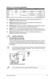
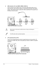
... INIT# SLIN# GND GND GND GND GND GND GND GND STB# PD0 PD1 PD2 PD3 PD4 PD5 PD6 PD7 ACK# BUSY PE SLCT P5G43T-M PRO PIN 1 P5G43T-M PRO Parallel Port Connector 1-26 Chapter 1: Product introduction USB connectors (10-1 pin USB78, USB910, USB1112) These connectors are for USB 2.0... USB_P12USB_P12+ GND NC USB+5V USB_P7USB_P7+ GND P5G43T-M PRO USB1112 PIN 1 USB910 PIN 1 USB+5V USB_P11USB_P11+ GND P5G43T-M PRO USB2.0 connectors USB+5V USB_P9USB_P9+ GND USB78 PIN 1 Never connect a 1394 cable to the USB connectors. Doing so will damage the motherboard! LPT connector (26-1 pin LPT) The ...
... INIT# SLIN# GND GND GND GND GND GND GND GND STB# PD0 PD1 PD2 PD3 PD4 PD5 PD6 PD7 ACK# BUSY PE SLCT P5G43T-M PRO PIN 1 P5G43T-M PRO Parallel Port Connector 1-26 Chapter 1: Product introduction USB connectors (10-1 pin USB78, USB910, USB1112) These connectors are for USB 2.0... USB_P12USB_P12+ GND NC USB+5V USB_P7USB_P7+ GND P5G43T-M PRO USB1112 PIN 1 USB910 PIN 1 USB+5V USB_P11USB_P11+ GND P5G43T-M PRO USB2.0 connectors USB+5V USB_P9USB_P9+ GND USB78 PIN 1 Never connect a 1394 cable to the USB connectors. Doing so will damage the motherboard! LPT connector (26-1 pin LPT) The ...


