User Manual
Page 9
... connector 1 x Chassis fan connector 1 x 24-pin EATX power connector 1 x 4-pin ATX 12V power connector 1 x Chassis intrusion connector (optional for P5G41T-M LX2 and P5G41T-M LX2/GB) 1 x Floppy disk drive connector (optional for P5G41T-M LX2 and P5G41T-M LX2/GB) ASUS CrashFree BIOS 3 ASUS Q-Fan ASUS EZ Flash 2 ASUS MyLogo 2 8Mb Flash ROM, AMI BIOS, PnP, DMI 2.0, WfM 2.0, ACPI 2.0a, SM BIOS 2.5 WOL, PXE, PME Wake up, WOR...
... connector 1 x Chassis fan connector 1 x 24-pin EATX power connector 1 x 4-pin ATX 12V power connector 1 x Chassis intrusion connector (optional for P5G41T-M LX2 and P5G41T-M LX2/GB) 1 x Floppy disk drive connector (optional for P5G41T-M LX2 and P5G41T-M LX2/GB) ASUS CrashFree BIOS 3 ASUS Q-Fan ASUS EZ Flash 2 ASUS MyLogo 2 8Mb Flash ROM, AMI BIOS, PnP, DMI 2.0, WfM 2.0, ACPI 2.0a, SM BIOS 2.5 WOL, PXE, PME Wake up, WOR...
User Manual
Page 11
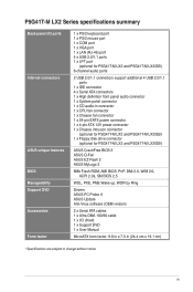
... 9LPRS441 Intel® G41 Lithium Cell CMOS Power PRI_IDE 7 2 24.4cm(9.6in) EATXPWR Super PCIEX16 I/O 17 P5G41T-M LX2/GB/LPT SATA4 SATA3 8Mb PCI1 Intel® SATA2 BIOS SATA1 ICH7 PCI2 8 VIA VT1705 CD FLOPPY SB_PWR USBPW5-8 USB56...• P5G41T-M LX2 integrates the Realtek® RTL8103EL Fast Ethernet controller. • P5G41T-M LX2/GB and P5G41T-M LX2/GB/LPT integrate the Realtek® RTL8112L Gigabit Ethernet controller. • The floppy disk drive connector, chassis intrusion connector, and LPT port are optional items for P5G41T-M LX2 and P5G41T-M LX2/GB. Doing ...
... 9LPRS441 Intel® G41 Lithium Cell CMOS Power PRI_IDE 7 2 24.4cm(9.6in) EATXPWR Super PCIEX16 I/O 17 P5G41T-M LX2/GB/LPT SATA4 SATA3 8Mb PCI1 Intel® SATA2 BIOS SATA1 ICH7 PCI2 8 VIA VT1705 CD FLOPPY SB_PWR USBPW5-8 USB56...• P5G41T-M LX2 integrates the Realtek® RTL8103EL Fast Ethernet controller. • P5G41T-M LX2/GB and P5G41T-M LX2/GB/LPT integrate the Realtek® RTL8112L Gigabit Ethernet controller. • The floppy disk drive connector, chassis intrusion connector, and LPT port are optional items for P5G41T-M LX2 and P5G41T-M LX2/GB. Doing ...
User Manual
Page 20
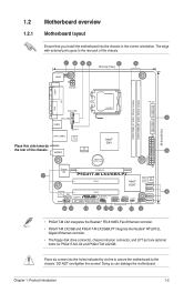
...drives. Serial ATA connectors (7-pin SATA1-4) These connectors are not jumpers! The data transfer rate of the connector. GND RSATA_RXN4 RSATA_RXP4 GND RSATA_TXN4 RSATA_TXP4 GND SATA4 GND RSATA_RXN3 RSATA_RXP3 GND RSATA_TXN3 RSATA_TXP3 GND SATA3 GND RSATA_RXN2 RSATA_RXP2 GND RSATA_TXN2 RSATA_TXP2 GND GND RSATA_RXN1 RSATA_RXP1 GND RSATA_TXN1 RSATA_TXP1 GND P5G41T-M LX2/GB/LPT SATA2 SATA1 P5G41T-M LX2/GB.../LPT SATA connectors 1-11 ASUS P5G41T-M LX2 Series CPU and Chassis fan ...
...drives. Serial ATA connectors (7-pin SATA1-4) These connectors are not jumpers! The data transfer rate of the connector. GND RSATA_RXN4 RSATA_RXP4 GND RSATA_TXN4 RSATA_TXP4 GND SATA4 GND RSATA_RXN3 RSATA_RXP3 GND RSATA_TXN3 RSATA_TXP3 GND SATA3 GND RSATA_RXN2 RSATA_RXP2 GND RSATA_TXN2 RSATA_TXP2 GND GND RSATA_RXN1 RSATA_RXP1 GND RSATA_TXN1 RSATA_TXP1 GND P5G41T-M LX2/GB/LPT SATA2 SATA1 P5G41T-M LX2/GB.../LPT SATA connectors 1-11 ASUS P5G41T-M LX2 Series CPU and Chassis fan ...
User Manual
Page 21
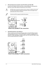
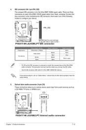
... CD-ROM, TV tuner, or MPEG card. Optical drive audio connector (4-pin CD) These connectors allow you connect the IDE cable. • Use the 80-conductor IDE cable for the Ultra DMA 100/66 signal cable. PIN1 PRI_IDE P5G41T-M LX2/GB/LPT NOTE:Orient the red markings on the Ultra DMA...audio input from sound sources such as "Cable-Select," ensure that all other device jumpers have the same setting. 5. P5G41T-M LX2/GB/LPT IDE connector Single device Two devices Drive jumper setting Cable-Select or Master Cable-Select Master Slave Mode of the following modes to PIN 1. Master Slave Master ...
... CD-ROM, TV tuner, or MPEG card. Optical drive audio connector (4-pin CD) These connectors allow you connect the IDE cable. • Use the 80-conductor IDE cable for the Ultra DMA 100/66 signal cable. PIN1 PRI_IDE P5G41T-M LX2/GB/LPT NOTE:Orient the red markings on the Ultra DMA...audio input from sound sources such as "Cable-Select," ensure that all other device jumpers have the same setting. 5. P5G41T-M LX2/GB/LPT IDE connector Single device Two devices Drive jumper setting Cable-Select or Master Cable-Select Master Slave Mode of the following modes to PIN 1. Master Slave Master ...
User Manual
Page 22
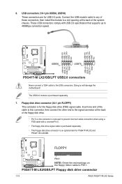
.... P5G41T-M LX2/GB/LPT Floppy disk drive connector 1-13 ASUS P5G41T-M LX2 Series Connect the USB module cable to any of the system chassis. USB+5V USB_P8USB_P8+ GND NC USB+5V USB_P6USB_P6+ GND NC P5G41T-M LX2/GB/LPT USB56 PIN 1 USB78 PIN 1 USB+5V USB_P7USB_P7+ GND USB+5V USB_P5USB_P5+ GND P5G41T-M LX2/GB/LPT USB2.0 connectors Never connect a 1394 cable to PIN 1. FLOPPY P5G41T-M LX2/GB...
.... P5G41T-M LX2/GB/LPT Floppy disk drive connector 1-13 ASUS P5G41T-M LX2 Series Connect the USB module cable to any of the system chassis. USB+5V USB_P8USB_P8+ GND NC USB+5V USB_P6USB_P6+ GND NC P5G41T-M LX2/GB/LPT USB56 PIN 1 USB78 PIN 1 USB+5V USB_P7USB_P7+ GND USB+5V USB_P5USB_P5+ GND P5G41T-M LX2/GB/LPT USB2.0 connectors Never connect a 1394 cable to PIN 1. FLOPPY P5G41T-M LX2/GB...
User Manual
Page 24
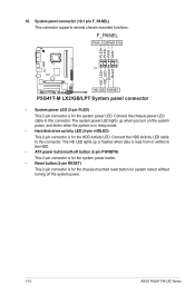
... PWR LED PWR BTN PIN 1 P5G41T-M LX2/GB/LPT HD LED RESET P5G41T-M LX2/GB/LPT System panel connector • System power LED (2-pin PLED) This 2-pin connector is for the chassis-mounted reset button for system reboot without turning off the system power. 1-15 ASUS P5G41T-M LX2 Series The HD LED lights up when... you turn on the system power, and blinks when the system is in sleep mode. • Hard disk drive activity LED (2-pin +HDLED) This 2-pin connector is for the...
... PWR LED PWR BTN PIN 1 P5G41T-M LX2/GB/LPT HD LED RESET P5G41T-M LX2/GB/LPT System panel connector • System power LED (2-pin PLED) This 2-pin connector is for the chassis-mounted reset button for system reboot without turning off the system power. 1-15 ASUS P5G41T-M LX2 Series The HD LED lights up when... you turn on the system power, and blinks when the system is in sleep mode. • Hard disk drive activity LED (2-pin +HDLED) This 2-pin connector is for the...
User Manual
Page 27
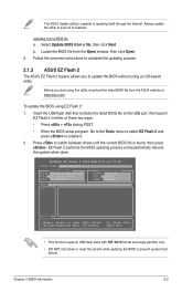
Locate the BIOS file from a file, then click Next. Insert the USB flash disk that contains the latest BIOS file to switch between drives until the correct BIOS file is capable of these two ways: • Press + during POST. • Enter the BIOS setup program. Select Update ...you start using this utility, download the latest BIOS file from a BIOS file a. The ASUS Update utility is found, then press . ASUSTek EZ Flash 2 BIOS ROM Utility V3.44 FLASH TYPE: MXIC 25L8005 Current ROM BOARD:P5G41T-M LX2/GB/LPT VER:0305 (H:00 B:00) DATE: 10/29/2009 Update ROM BOARD: Unknown VER...
Locate the BIOS file from a file, then click Next. Insert the USB flash disk that contains the latest BIOS file to switch between drives until the correct BIOS file is capable of these two ways: • Press + during POST. • Enter the BIOS setup program. Select Update ...you start using this utility, download the latest BIOS file from a BIOS file a. The ASUS Update utility is found, then press . ASUSTek EZ Flash 2 BIOS ROM Utility V3.44 FLASH TYPE: MXIC 25L8005 Current ROM BOARD:P5G41T-M LX2/GB/LPT VER:0305 (H:00 B:00) DATE: 10/29/2009 Update ROM BOARD: Unknown VER...
User Manual
Page 28
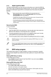
...Setup Defaults item under the Exit menu. Ensure to load the BIOS default settings to the floppy disk drive, if supported. 3. 2.1.3 ASUS CrashFree BIOS The ASUS CrashFree BIOS is an auto recovery tool that allows you to restore the BIOS file when it fails or...Do this utility, rename the BIOS file in the removable device into PG41TML2.ROM (P5G41T-M LX2) / PG41TMLG.ROM (P5G41T-M LX2/GB) / PG41TMLP.ROM (P5G41T-M LX2/GB/LPT). • The BIOS file in using the first two options. 2-3 ASUS P5G41T-M LX2 Series When found, the utility reads the BIOS file and starts flashing the corrupted BIOS...
...Setup Defaults item under the Exit menu. Ensure to load the BIOS default settings to the floppy disk drive, if supported. 3. 2.1.3 ASUS CrashFree BIOS The ASUS CrashFree BIOS is an auto recovery tool that allows you to restore the BIOS file when it fails or...Do this utility, rename the BIOS file in the removable device into PG41TML2.ROM (P5G41T-M LX2) / PG41TMLG.ROM (P5G41T-M LX2/GB) / PG41TMLP.ROM (P5G41T-M LX2/GB/LPT). • The BIOS file in using the first two options. 2-3 ASUS P5G41T-M LX2 Series When found, the utility reads the BIOS file and starts flashing the corrupted BIOS...
User Manual
Page 29
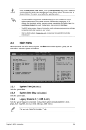
... reference purposes only, and may not exactly match what you an overview of floppy drive installed. We recommend to always shut down the system properly from a running operating system...the Main menu screen appears, giving you see on your screen. • Visit the ASUS website at www.asus.com to your data or system. See section 2.8 Exit Menu. • The BIOS ... Date [Day xx/xx/xxxx] Sets the system date. 2.3.3 Legacy Diskette A [1.44M, 3.5 in .] This item is for P5G41T-M LX2/GB/LPT only. Configuration options: [Disabled] [360K, 5.25 in.] [1.2M, 5.25 in.] [720K, 3.5 in.] [1.44M, ...
... reference purposes only, and may not exactly match what you an overview of floppy drive installed. We recommend to always shut down the system properly from a running operating system...the Main menu screen appears, giving you see on your screen. • Visit the ASUS website at www.asus.com to your data or system. See section 2.8 Exit Menu. • The BIOS ... Date [Day xx/xx/xxxx] Sets the system date. 2.3.3 Legacy Diskette A [1.44M, 3.5 in .] This item is for P5G41T-M LX2/GB/LPT only. Configuration options: [Disabled] [360K, 5.25 in.] [1.2M, 5.25 in.] [720K, 3.5 in.] [1.44M, ...


