User Manual
Page 3
... Safety information vii P5G41-M SI specifications summary viii Chapter 1: Product introduction 1.1 Before you proceed 1-1 1.2 Motherboard overview 1-2 1.2.1 Motherboard layout 1-2 1.2.2 Layout contents 1-2 1.3 Central Processing Unit (CPU 1-3 1.4 System memory 1-3 1.4.1 Overview 1-3 1.4.2 Memory configurations 1-4 1.5 Expansion slots 1-6 1.5.1 Installing an expansion card 1-6 1.5.2 Configuring an expansion card 1-7 1.5.3 PCI slots 1-7 1.5.4 PCI Express x16 slot 1-7 1.6 Jumpers 1-7 1.7 Connectors 1-9 1.7.1 Rear panel ports 1-9 1.7.2 Internal connectors 1-10...
... Safety information vii P5G41-M SI specifications summary viii Chapter 1: Product introduction 1.1 Before you proceed 1-1 1.2 Motherboard overview 1-2 1.2.1 Motherboard layout 1-2 1.2.2 Layout contents 1-2 1.3 Central Processing Unit (CPU 1-3 1.4 System memory 1-3 1.4.1 Overview 1-3 1.4.2 Memory configurations 1-4 1.5 Expansion slots 1-6 1.5.1 Installing an expansion card 1-6 1.5.2 Configuring an expansion card 1-7 1.5.3 PCI slots 1-7 1.5.4 PCI Express x16 slot 1-7 1.6 Jumpers 1-7 1.7 Connectors 1-9 1.7.1 Rear panel ports 1-9 1.7.2 Internal connectors 1-10...
User Manual
Page 8
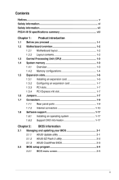
... LAN controller VT1708S High Definition Audio 6-channel CODEC Supports Multi-Streaming 8 x USB 2.0/1.1 ports (4 ports at mid-board, 4 ports at back panel) ASUS CrashFree BIOS 3 ASUS EZ Flash2 ASUS AI NET2 ASUS MyLogo 2 ASUS Q-Fan (continued on the next page) viii We recommend a maximum of 3GB system memory... modules - resolution: 2048 x 1536 x 32Bpp @75Hz DVI Max. resolution: 1920 x 1200 x 32Bpp @60Hz HDMI Max. P5G41-M SI specifications summary CPU Chipset System bus Memory Expansion slots VGA Storage LAN Audio USB ASUS Special features LGA775 Socket for Intel® C��o&#...
... LAN controller VT1708S High Definition Audio 6-channel CODEC Supports Multi-Streaming 8 x USB 2.0/1.1 ports (4 ports at mid-board, 4 ports at back panel) ASUS CrashFree BIOS 3 ASUS EZ Flash2 ASUS AI NET2 ASUS MyLogo 2 ASUS Q-Fan (continued on the next page) viii We recommend a maximum of 3GB system memory... modules - resolution: 2048 x 1536 x 32Bpp @75Hz DVI Max. resolution: 1920 x 1200 x 32Bpp @60Hz HDMI Max. P5G41-M SI specifications summary CPU Chipset System bus Memory Expansion slots VGA Storage LAN Audio USB ASUS Special features LGA775 Socket for Intel® C��o&#...
User Manual
Page 9
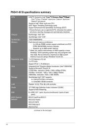
...P5G41-M SI specifications summary Rear panel ports Internal connectors BIOS features Manageability Accessories Support DVD Form factor 1 x PS/2 keyboard port 1 x PS/2 mouse port 1 x LAN (RJ-45) port 4 x USB 2.0/1.1 ports 6-channel audio I/O port 1 x VGA port 1 x DVI port 1 x HDMI port 1 x COM port 1 x High Definition front panel audio connector 1 x S/PDIF out connector 1 x System panel connector 2 x USB 2.0 connectors support additional 4 USB 2.0 ports... cable 1 x I/O shield User Manual 1 x Support DVD Drivers ASUS Update ASUS PC Probe II Anti-virus software (OEM version) MicroATX form factor:...
...P5G41-M SI specifications summary Rear panel ports Internal connectors BIOS features Manageability Accessories Support DVD Form factor 1 x PS/2 keyboard port 1 x PS/2 mouse port 1 x LAN (RJ-45) port 4 x USB 2.0/1.1 ports 6-channel audio I/O port 1 x VGA port 1 x DVI port 1 x HDMI port 1 x COM port 1 x High Definition front panel audio connector 1 x S/PDIF out connector 1 x System panel connector 2 x USB 2.0 connectors support additional 4 USB 2.0 ports... cable 1 x I/O shield User Manual 1 x Support DVD Drivers ASUS Update ASUS PC Probe II Anti-virus software (OEM version) MicroATX form factor:...

User Manual
Page 11
...) 1-14 ASUS P5G41-M SI 1-2 Floppy disk drive connector (34-1 pin 1-16 FLOPPY) 1-3 17. Optical drive audio in the correct orientation. Intel CPU socket 7. Doing so can damage the motherboard. 1.2.2 Layout contents Connectors/Jumpers/Slots/LED 1. IDE connector (40-1 pin PRI_IDE) 1-13 13. DO NOT overtighten the screws! The edge with external ports goes to...
...) 1-14 ASUS P5G41-M SI 1-2 Floppy disk drive connector (34-1 pin 1-16 FLOPPY) 1-3 17. Optical drive audio in the correct orientation. Intel CPU socket 7. Doing so can damage the motherboard. 1.2.2 Layout contents Connectors/Jumpers/Slots/LED 1. IDE connector (40-1 pin PRI_IDE) 1-13 13. DO NOT overtighten the screws! The edge with external ports goes to...

User Manual
Page 17
... port; Shut down and cut off the AC power, then reboot the system, the BIOS automatically resets parameter settings to clear the CMOS RTC RAM data. For system failure due to overclocking. USBPW1-4 12 23 +5V +5VSB (Default) USBPW5-8 P5G41-M SI 12 23 +5V +5VSB (Default) P5G41-M SI ...2-3 (+5VSB), you to enable or disable the keyboard wake-up from S1 sleep mode (CPU stopped, DRAM refreshed, system running in sleep mode. ASUS P5G41-M SI 1-8 After clearing the CMOS, reinstall the battery. • You do not help, remove the onboard battery and move the jumper again to default...
... port; Shut down and cut off the AC power, then reboot the system, the BIOS automatically resets parameter settings to clear the CMOS RTC RAM data. For system failure due to overclocking. USBPW1-4 12 23 +5V +5VSB (Default) USBPW5-8 P5G41-M SI 12 23 +5V +5VSB (Default) P5G41-M SI ...2-3 (+5VSB), you to enable or disable the keyboard wake-up from S1 sleep mode (CPU stopped, DRAM refreshed, system running in sleep mode. ASUS P5G41-M SI 1-8 After clearing the CMOS, reinstall the battery. • You do not help, remove the onboard battery and move the jumper again to default...
User Manual
Page 18
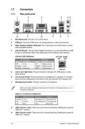
... Line In Line Out Mic In 4-channel Rear Speaker Out Front Speaker Out Mic In 6-channel Rear Speaker Out Front Speaker Out Bass/Center 8. LAN port LED indications ACT/LINK LED SPEED LED ACT/LINK SPEED LED LED Status Description Status Description OFF No link OFF 10 Mbps connection ORANGE Linked...
... Line In Line Out Mic In 4-channel Rear Speaker Out Front Speaker Out Mic In 6-channel Rear Speaker Out Front Speaker Out Bass/Center 8. LAN port LED indications ACT/LINK LED SPEED LED ACT/LINK SPEED LED LED Status Description Status Description OFF No link OFF 10 Mbps connection ORANGE Linked...
User Manual
Page 19
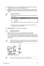
... cooling fans of 350 mA ~ 2000 mA (24 W max.) or a total of HD DVD, Blu-Ray and other protected content. They are supported for any DVI-D compatible device. ASUS P5G41-M SI 1-10 HDMI port. This port is for a High-Definition Multimedia Interface (HDMI) connector, and is for a PS/2 keyboard. 1.7.2 Internal connectors 1. 10. PS/2 Keyboard...
... cooling fans of 350 mA ~ 2000 mA (24 W max.) or a total of HD DVD, Blu-Ray and other protected content. They are supported for any DVI-D compatible device. ASUS P5G41-M SI 1-10 HDMI port. This port is for a High-Definition Multimedia Interface (HDMI) connector, and is for a PS/2 keyboard. 1.7.2 Internal connectors 1. 10. PS/2 Keyboard...
User Manual
Page 21
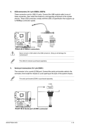
....0 connectors Never connect a 1394 cable to 480Mbps connection speed. Doing so will damage the motherboard! COM1 PIN 1 P5G41-M SI P5G41-M SI Serial port (COM1) connector ASUS P5G41-M SI 1-12 The serial port bracket (COM1) is purchased separately. 5. 4. Connect the serial port module cable to the connector, then install the module to a slot opening at the back of the system chassis...
....0 connectors Never connect a 1394 cable to 480Mbps connection speed. Doing so will damage the motherboard! COM1 PIN 1 P5G41-M SI P5G41-M SI Serial port (COM1) connector ASUS P5G41-M SI 1-12 The serial port bracket (COM1) is purchased separately. 5. 4. Connect the serial port module cable to the connector, then install the module to a slot opening at the back of the system chassis...
User Manual
Page 24
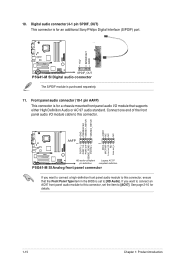
... 1 PIN 1 MIC2 MICPWR Line out_R NC Line out_L PORT1 L PORT1 R PORT2 R SENSE_SEND PORT2 L P5G41-M SI HD-audio-compliant Legacy AC'97 pin definition compliant definition P5G41-M SI Analog front panel connector If you want to connect a high-definition front panel audio module to this connector,...module to this connector, set to [AC97]. See page 2-10 for an additional Sony/Philips Digital Interface (S/PDIF) port. +5V SPDIFOUT GND P5G41-M SI SPDIF_OUT P5G41-M SI Digital audio connector The S/PDIF module is for a chassis-mounted front panel audio I /O module cable to this connector. 10...
... 1 PIN 1 MIC2 MICPWR Line out_R NC Line out_L PORT1 L PORT1 R PORT2 R SENSE_SEND PORT2 L P5G41-M SI HD-audio-compliant Legacy AC'97 pin definition compliant definition P5G41-M SI Analog front panel connector If you want to connect a high-definition front panel audio module to this connector,...module to this connector, set to [AC97]. See page 2-10 for an additional Sony/Philips Digital Interface (S/PDIF) port. +5V SPDIFOUT GND P5G41-M SI SPDIF_OUT P5G41-M SI Digital audio connector The S/PDIF module is for a chassis-mounted front panel audio I /O module cable to this connector. 10...
User Manual
Page 25
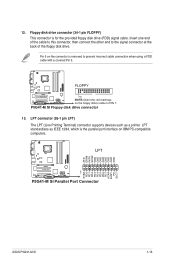
... which is the parallel port interface on the floppy ribbon cable to PIN 1. Floppy disk drive connector (34-1 pin FLOPPY) This connector is removed to the signal connector at the back of the floppy disk drive. LPT standardizes as a printer. P5G41-M SI Floppy disk drive connector 13. FLOPPY P5G41-M SI PIN1 NOTE:Orient the ...# INIT# SLIN# GND GND GND GND GND GND GND GND PIN 1 STB# PD0 PD1 PD2 PD3 PD4 PD5 PD6 PD7 ACK# BUSY PE SLCT P5G41-M SI P5G41-M SI Parallel Port Connector ASUS P5G41-M SI 1-16 Pin 5 on the connector is for the provided floppy disk drive (FDD) signal cable. 12.
... which is the parallel port interface on the floppy ribbon cable to PIN 1. Floppy disk drive connector (34-1 pin FLOPPY) This connector is removed to the signal connector at the back of the floppy disk drive. LPT standardizes as a printer. P5G41-M SI Floppy disk drive connector 13. FLOPPY P5G41-M SI PIN1 NOTE:Orient the ...# INIT# SLIN# GND GND GND GND GND GND GND GND PIN 1 STB# PD0 PD1 PD2 PD3 PD4 PD5 PD6 PD7 ACK# BUSY PE SLCT P5G41-M SI P5G41-M SI Parallel Port Connector ASUS P5G41-M SI 1-16 Pin 5 on the connector is for the provided floppy disk drive (FDD) signal cable. 12.
User Manual
Page 28
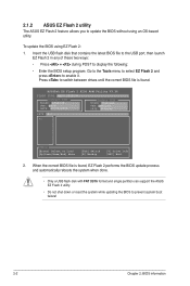
.... Insert the USB flash disk that contains the latest BIOS file to the USB port, then launch EZ Flash 2 in any of these two ways: • Press + during POST to enable it. 2.1.2 ASUS EZ Flash 2 utility The ASUS EZ Flash 2 feature allows you to update the BIOS without using EZ Flash 2:... 1. ASUSTek EZ Flash 2 BIOS ROM Utility V3.36 FLASH TYPE: MXIC 25L8005 Current ROM BOARD: P5G41-M VER: 0203 DATE: 07/10/2009 Update ROM BOARD...
.... Insert the USB flash disk that contains the latest BIOS file to the USB port, then launch EZ Flash 2 in any of these two ways: • Press + during POST to enable it. 2.1.2 ASUS EZ Flash 2 utility The ASUS EZ Flash 2 feature allows you to update the BIOS without using EZ Flash 2:... 1. ASUSTek EZ Flash 2 BIOS ROM Utility V3.36 FLASH TYPE: MXIC 25L8005 Current ROM BOARD: P5G41-M VER: 0203 DATE: 07/10/2009 Update ROM BOARD...
User Manual
Page 29
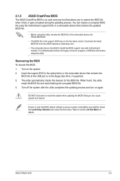
... for details. Select the Load Setup Defaults item under the Exit menu. 2.1.3 ASUS CrashFree BIOS The ASUS CrashFree BIOS is an auto recovery tool that contains the BIOS file to the USB port or to the floppy disk drive, if supported. 3. For motherboards without the ...found, the utility reads the BIOS file and starts flashing the corrupted BIOS file. 4. ASUS P5G41-M SI 2-3 Refer to ensure system compatibility and stability. Download the latest BIOS file from the ASUS website at www.asus.com. • The removable device that contains the updated BIOS file. • Before...
... for details. Select the Load Setup Defaults item under the Exit menu. 2.1.3 ASUS CrashFree BIOS The ASUS CrashFree BIOS is an auto recovery tool that contains the BIOS file to the USB port or to the floppy disk drive, if supported. 3. For motherboards without the ...found, the utility reads the BIOS file and starts flashing the corrupted BIOS file. 4. ASUS P5G41-M SI 2-3 Refer to ensure system compatibility and stability. Download the latest BIOS file from the ASUS website at www.asus.com. • The removable device that contains the updated BIOS file. • Before...


