User Manual
Page 5
...instructions, may cause harmful interference to enable proper reuse of the FCC Rules. DO NOT throw the motherboard in our products at ASUS REACH website at http://green.asus.com/english/REACH.htm. DO NOT throw the mercury-containing button cell battery in a particular installation. The use of shielded... cables for help. Changes or modifications to this unit not expressly approved by one or more of the crossed out wheeled bin ...
...instructions, may cause harmful interference to enable proper reuse of the FCC Rules. DO NOT throw the motherboard in our products at ASUS REACH website at http://green.asus.com/english/REACH.htm. DO NOT throw the mercury-containing button cell battery in a particular installation. The use of shielded... cables for help. Changes or modifications to this unit not expressly approved by one or more of the crossed out wheeled bin ...

User Manual
Page 6
...system before you add a device. • Before connecting or removing signal cables from the motherboard, ensure that all power cables are unplugged. • Seek professional assistance before the signal cables are connected. These devices could explode and release harmful substances into the environment...the product, contact a qualified service technician or your regular household waste. Take it , carefully read all cables are correctly connected and the power cables are not damaged. This motherboard should only be included in fire. Safety information Electrical safety • To...
...system before you add a device. • Before connecting or removing signal cables from the motherboard, ensure that all power cables are unplugged. • Seek professional assistance before the signal cables are connected. These devices could explode and release harmful substances into the environment...the product, contact a qualified service technician or your regular household waste. Take it , carefully read all cables are correctly connected and the power cables are not damaged. This motherboard should only be included in fire. Safety information Electrical safety • To...

User Manual
Page 7
... system before you add a device. • Before connecting or removing signal cables from the system, ensure that all power cables are unplugged. • Seek professional assistance before the signal cables are connected. These devices could interrupt the grounding circuit. • Make sure...damage to the components when trying to emphasize a word or a phrase. Italics Used to complete a task. ASUS websites The ASUS website provides updated information on ASUS hardware and software products. These documents are linked with a plus sign (+). Conventions used throughout this guide To ...
... system before you add a device. • Before connecting or removing signal cables from the system, ensure that all power cables are unplugged. • Seek professional assistance before the signal cables are connected. These devices could interrupt the grounding circuit. • Make sure...damage to the components when trying to emphasize a word or a phrase. Italics Used to complete a task. ASUS websites The ASUS website provides updated information on ASUS hardware and software products. These documents are linked with a plus sign (+). Conventions used throughout this guide To ...
User Manual
Page 9
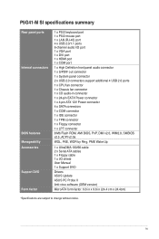
P5G41-M SI specifications summary Rear panel ports Internal connectors BIOS features Manageability Accessories Support DVD Form factor 1 x PS/2 keyboard port 1 x PS/2 mouse port 1 x LAN (RJ-45) port 4 x USB 2.0/1.1 ports 6-channel audio I/O port 1 x VGA port 1 x DVI port 1 x HDMI port 1 x COM port 1 x High Definition front panel ... ACPI v2.0a WOL, PXE, WOR by Ring, PME Wake Up 1 x UltraDMA 100/66 cable 2 x Serial ATA cables 1 x Floppy cable 1 x I/O shield User Manual 1 x Support DVD Drivers ASUS Update ASUS PC Probe II Anti-virus software (OEM version) MicroATX form factor: 9.6 in x 9.6 in (...
P5G41-M SI specifications summary Rear panel ports Internal connectors BIOS features Manageability Accessories Support DVD Form factor 1 x PS/2 keyboard port 1 x PS/2 mouse port 1 x LAN (RJ-45) port 4 x USB 2.0/1.1 ports 6-channel audio I/O port 1 x VGA port 1 x DVI port 1 x HDMI port 1 x COM port 1 x High Definition front panel ... ACPI v2.0a WOL, PXE, WOR by Ring, PME Wake Up 1 x UltraDMA 100/66 cable 2 x Serial ATA cables 1 x Floppy cable 1 x I/O shield User Manual 1 x Support DVD Drivers ASUS Update ASUS PC Probe II Anti-virus software (OEM version) MicroATX form factor: 9.6 in x 9.6 in (...
User Manual
Page 10
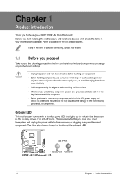
...it, check the items in any component, switch off mode. This is a reminder that you must shut down the system and unplug the power cable before removing or plugging in your retailer. 1.1 Before you proceed Take note of the following precautions before you install motherboard components or change any ... due to static electricity • Hold components by the edges to the motherboard, peripherals, or components. Refer to page ix for buying an ASUS® P5G41-M SI motherboard! If any of the items is ON, in sleep mode, or in the bag that the system is damaged or missing, contact your...
...it, check the items in any component, switch off mode. This is a reminder that you must shut down the system and unplug the power cable before removing or plugging in your retailer. 1.1 Before you proceed Take note of the following precautions before you install motherboard components or change any ... due to static electricity • Hold components by the edges to the motherboard, peripherals, or components. Refer to page ix for buying an ASUS® P5G41-M SI motherboard! If any of the items is ON, in sleep mode, or in the bag that the system is damaged or missing, contact your...
User Manual
Page 12
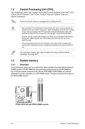
...cap. Contact your retailer immediately if the PnP cap is shipment/transit-related. • Keep the cap after installing the motherboard. ASUS will shoulder the cost of the motherboard, ensure that the PnP cap is on a DDR DIMM socket. DDR2 DIMMs are unplugged ...installation/removal, or misplacement/loss/incorrect removal of the DDR2 DIMM sockets: DIMM_A1 DIMM_A2 DIMM_B1 DIMM_B2 P5G41-M SI P5G41-M SI 240-pin DDR2 DIMM sockets 1-3 Chapter 1: Product introduction Ensure that all power cables are notched differently to the 184-pin DDR DIMM. 1.3 Central Processing Unit (CPU) This ...
...cap. Contact your retailer immediately if the PnP cap is shipment/transit-related. • Keep the cap after installing the motherboard. ASUS will shoulder the cost of the motherboard, ensure that the PnP cap is on a DDR DIMM socket. DDR2 DIMMs are unplugged ...installation/removal, or misplacement/loss/incorrect removal of the DDR2 DIMM sockets: DIMM_A1 DIMM_A2 DIMM_B1 DIMM_B2 P5G41-M SI P5G41-M SI 240-pin DDR2 DIMM sockets 1-3 Chapter 1: Product introduction Ensure that all power cables are notched differently to the 184-pin DDR DIMM. 1.3 Central Processing Unit (CPU) This ...
User Manual
Page 19
DVI port. ASUS P5G41-M SI 1-10 This port is for a High-Definition Multimedia Interface (HDMI) connector, and is for a PS/2 keyboard. 1.7.2 Internal connectors 1. This port is HDCP compliant allowing playback of HD DVD, Blu-Ray and other protected content. DO NOT forget to connect the fan cables to the fan connectors on the fan connectors. The...
DVI port. ASUS P5G41-M SI 1-10 This port is for a High-Definition Multimedia Interface (HDMI) connector, and is for a PS/2 keyboard. 1.7.2 Internal connectors 1. This port is HDCP compliant allowing playback of HD DVD, Blu-Ray and other protected content. DO NOT forget to connect the fan cables to the fan connectors on the fan connectors. The...
User Manual
Page 20
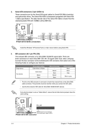
... Black Black Gray Black or gray • Pin 20 on each Ultra DMA 100 / 66 / 33 signal cable: blue, black, and gray. P5G41-M SI SATA4 SATA3 SATA2 SATA1 GND RSATA_TXP4 RSATA_TXN4 GND RSATA_RXP4 RSATA_RXN4 GND GND RSATA_TXP3 RSATA_TXN3 GND RSATA_RXP3 RSATA_RXN3 GND GND RSATA_TXP2 RSATA_TXN2 GND...the Serial ATA 3Gb/s is for Ultra DMA 100/66/33 IDE devices. There are for the Serial ATA signal cables for Serial ATA 3Gb/s hard disk and optical disk drives. P5G41-M SI IDE connector 1-11 Chapter 1: Product introduction If any device jumper is removed to PIN 1. Serial ATA connectors (7-pin...
... Black Black Gray Black or gray • Pin 20 on each Ultra DMA 100 / 66 / 33 signal cable: blue, black, and gray. P5G41-M SI SATA4 SATA3 SATA2 SATA1 GND RSATA_TXP4 RSATA_TXN4 GND RSATA_RXP4 RSATA_RXN4 GND GND RSATA_TXP3 RSATA_TXN3 GND RSATA_RXP3 RSATA_RXN3 GND GND RSATA_TXP2 RSATA_TXN2 GND...the Serial ATA 3Gb/s is for Ultra DMA 100/66/33 IDE devices. There are for the Serial ATA signal cables for Serial ATA 3Gb/s hard disk and optical disk drives. P5G41-M SI IDE connector 1-11 Chapter 1: Product introduction If any device jumper is removed to PIN 1. Serial ATA connectors (7-pin...
User Manual
Page 21
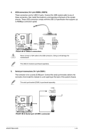
USB+5V USB_P8USB_P8+ GND NC USB+5V USB_P6USB_P6+ GND NC P5G41-M SI USB56 PIN 1 USB78 PIN 1 USB+5V USB_P7USB_P7+ GND USB+5V USB_P5USB_P5+ GND P5G41-M SI USB2.0 connectors Never connect a 1394 cable to 480Mbps connection speed. Doing so will damage the motherboard! 4. The USB 2.0 module is ... install the module to a slot opening at the back of the system chassis. COM1 PIN 1 P5G41-M SI P5G41-M SI Serial port (COM1) connector ASUS P5G41-M SI 1-12 Connect the USB module cable to any of these connectors, then install the module to a slot opening at the back of the...
USB+5V USB_P8USB_P8+ GND NC USB+5V USB_P6USB_P6+ GND NC P5G41-M SI USB56 PIN 1 USB78 PIN 1 USB+5V USB_P7USB_P7+ GND USB+5V USB_P5USB_P5+ GND P5G41-M SI USB2.0 connectors Never connect a 1394 cable to 480Mbps connection speed. Doing so will damage the motherboard! 4. The USB 2.0 module is ... install the module to a slot opening at the back of the system chassis. COM1 PIN 1 P5G41-M SI P5G41-M SI Serial port (COM1) connector ASUS P5G41-M SI 1-12 Connect the USB module cable to any of these connectors, then install the module to a slot opening at the back of the...
User Manual
Page 23
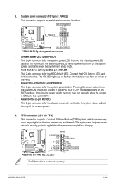
...system also helps enhance network security, protects digital identities, and ensures platform integrity. Connect the HDD Activity LED cable to this connector. TPM P5G41-M SI S_PWRDWN# GND +3VSB +3V F_LAD0 +3V F_LAD3 S_PLTRST# F_FRAME# C_PCICLK_TPM P5G41-M SI TPM Connector GND F_SERIRQ# GND F_LAD1 F_LAD2 S_SMBCLIK_MAIN S_SMBCLIK_MAIN GND PIN 1 The TPM module is read from or... separately. TPM connector (20-1 pin TPM) This connector supports a Trusted Platform Module (TPM) system, which can securely store keys, digital certificates, passwords, and data. ASUS P5G41-M SI 1-14
...system also helps enhance network security, protects digital identities, and ensures platform integrity. Connect the HDD Activity LED cable to this connector. TPM P5G41-M SI S_PWRDWN# GND +3VSB +3V F_LAD0 +3V F_LAD3 S_PLTRST# F_FRAME# C_PCICLK_TPM P5G41-M SI TPM Connector GND F_SERIRQ# GND F_LAD1 F_LAD2 S_SMBCLIK_MAIN S_SMBCLIK_MAIN GND PIN 1 The TPM module is read from or... separately. TPM connector (20-1 pin TPM) This connector supports a Trusted Platform Module (TPM) system, which can securely store keys, digital certificates, passwords, and data. ASUS P5G41-M SI 1-14
User Manual
Page 24
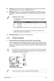
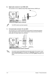
... the BIOS is for a chassis-mounted front panel audio I /O module cable to [HD Audio]. See page 2-10 for an additional Sony/Philips Digital Interface (S/PDIF) port. +5V SPDIFOUT GND P5G41-M SI SPDIF_OUT P5G41-M SI Digital audio connector The S/PDIF module is purchased separately. 11. GND PRESENCE... 1 PIN 1 MIC2 MICPWR Line out_R NC Line out_L PORT1 L PORT1 R PORT2 R SENSE_SEND PORT2 L P5G41-M SI HD-audio-compliant Legacy AC'97 pin definition compliant definition P5G41-M SI Analog front panel connector If you want to connect a high-definition front panel audio module to [AC97]....
... the BIOS is for a chassis-mounted front panel audio I /O module cable to [HD Audio]. See page 2-10 for an additional Sony/Philips Digital Interface (S/PDIF) port. +5V SPDIFOUT GND P5G41-M SI SPDIF_OUT P5G41-M SI Digital audio connector The S/PDIF module is purchased separately. 11. GND PRESENCE... 1 PIN 1 MIC2 MICPWR Line out_R NC Line out_L PORT1 L PORT1 R PORT2 R SENSE_SEND PORT2 L P5G41-M SI HD-audio-compliant Legacy AC'97 pin definition compliant definition P5G41-M SI Analog front panel connector If you want to connect a high-definition front panel audio module to [AC97]....
User Manual
Page 25
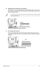
... 1 STB# PD0 PD1 PD2 PD3 PD4 PD5 PD6 PD7 ACK# BUSY PE SLCT P5G41-M SI P5G41-M SI Parallel Port Connector ASUS P5G41-M SI 1-16 Insert one end of the cable to this connector, then connect the other end to PIN 1. Pin 5 on the floppy ribbon cable to the signal connector at the back of the floppy disk drive. LPT...
... 1 STB# PD0 PD1 PD2 PD3 PD4 PD5 PD6 PD7 ACK# BUSY PE SLCT P5G41-M SI P5G41-M SI Parallel Port Connector ASUS P5G41-M SI 1-16 Insert one end of the cable to this connector, then connect the other end to PIN 1. Pin 5 on the floppy ribbon cable to the signal connector at the back of the floppy disk drive. LPT...
User Manual
Page 43
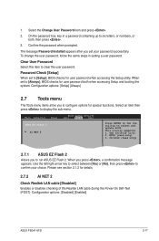
...Clear User Password Select this item to [Setup], BIOS checks for details. 2.7.2 AI NET 2 Check Realtek LAN cable [Disabled] Enables or disables checking of the Realtek LAN cable during the Power-On Self‑Test (POST). Password Check [Setup] When set your choice. 1. This ... update BIOS. NTFS (read only) 2.7.1 ASUS EZ Flash 2 Allows you to six letters, or numbers, or both when accessing Setup and booting the system. The message Password Installed appears after you press , a confirmation message appears. Configuration options: [Disabled] [Enabled] ASUS P5G41-M SI 2-17
...Clear User Password Select this item to [Setup], BIOS checks for details. 2.7.2 AI NET 2 Check Realtek LAN cable [Disabled] Enables or disables checking of the Realtek LAN cable during the Power-On Self‑Test (POST). Password Check [Setup] When set your choice. 1. This ... update BIOS. NTFS (read only) 2.7.1 ASUS EZ Flash 2 Allows you to six letters, or numbers, or both when accessing Setup and booting the system. The message Password Installed appears after you press , a confirmation message appears. Configuration options: [Disabled] [Enabled] ASUS P5G41-M SI 2-17


