
User Manual
Page 1
P5G41-M LX Motherboard
P5G41-M LX Motherboard
User Manual
Page 3
Contents Notices...v Safety information vi About this guide vii P5G41-M LX specifications summary viii Chapter 1: Product introduction 1.1 Before you proceed 1-1 1.2 Motherboard overview 1-2 1.2.1 Motherboard layout 1-2 1.2.2 Layout contents 1-2 1.3 Central Processing Unit (CPU 1-3 1.4 System memory 1-3 1.4.1 Overview 1-3 1.4.2 Memory configurations 1-4 1.5 Expansion slots... DVD information 1-16 Chapter 2: BIOS information 2.1 Managing and updating your BIOS 2-1 2.1.1 ASUS Update utility 2-1 2.1.2 ASUS EZ Flash 2 2-2 2.1.3 ASUS CrashFree BIOS 2-3 2.2 BIOS setup program 2-3 iii
Contents Notices...v Safety information vi About this guide vii P5G41-M LX specifications summary viii Chapter 1: Product introduction 1.1 Before you proceed 1-1 1.2 Motherboard overview 1-2 1.2.1 Motherboard layout 1-2 1.2.2 Layout contents 1-2 1.3 Central Processing Unit (CPU 1-3 1.4 System memory 1-3 1.4.1 Overview 1-3 1.4.2 Memory configurations 1-4 1.5 Expansion slots... DVD information 1-16 Chapter 2: BIOS information 2.1 Managing and updating your BIOS 2-1 2.1.1 ASUS Update utility 2-1 2.1.2 ASUS EZ Flash 2 2-2 2.1.3 ASUS CrashFree BIOS 2-3 2.2 BIOS setup program 2-3 iii

User Manual
Page 5
... battery should not be determined by turning the equipment off and on a circuit different from digital apparatus set out in our products at ASUS REACH website at http://green.asus.com/english/REACH.htm. This symbol of the crossed out wheeled bin indicates that interference will not occur in municipal waste. The... enable proper reuse of electronic products. This product has been designed to provide reasonable protection against harmful interference in municipal waste. DO NOT throw the motherboard in a residential installation.
... battery should not be determined by turning the equipment off and on a circuit different from digital apparatus set out in our products at ASUS REACH website at http://green.asus.com/english/REACH.htm. This symbol of the crossed out wheeled bin indicates that interference will not occur in municipal waste. The... enable proper reuse of electronic products. This product has been designed to provide reasonable protection against harmful interference in municipal waste. DO NOT throw the motherboard in a residential installation.

User Manual
Page 6
... away from connectors, slots, sockets and circuitry. • Avoid dust, humidity, and temperature extremes. Operation safety • Before installing the motherboard and adding devices on a stable surface. • If you are using the product, ensure that all power cables are unplugged. •...optical S/PDIF is an optional component (may or may become wet. vi If possible, disconnect all the manuals that came with your motherboard) and is defined as a CLASS 1 LASER PRODUCT. Safety information Electrical safety • To prevent electric shock hazard, disconnect the power...
... away from connectors, slots, sockets and circuitry. • Avoid dust, humidity, and temperature extremes. Operation safety • Before installing the motherboard and adding devices on a stable surface. • If you are using the product, ensure that all power cables are unplugged. •...optical S/PDIF is an optional component (may or may become wet. vi If possible, disconnect all the manuals that came with your motherboard) and is defined as a CLASS 1 LASER PRODUCT. Safety information Electrical safety • To prevent electric shock hazard, disconnect the power...
User Manual
Page 7
... documentation, such as warranty flyers, that you need when installing and configuring the motherboard. Detailed descriptions of the BIOS parameters are not part of the standard package. DANGER/WARNING: Information to prevent injury to yourself when trying to the ASUS contact information. 2. Optional documentation Your product package may have been added by...
... documentation, such as warranty flyers, that you need when installing and configuring the motherboard. Detailed descriptions of the BIOS parameters are not part of the standard package. DANGER/WARNING: Information to prevent injury to yourself when trying to the ASUS contact information. 2. Optional documentation Your product package may have been added by...
User Manual
Page 10
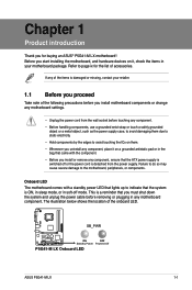
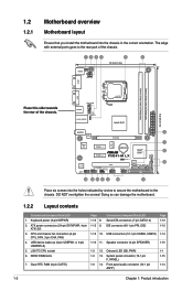
...Take note of the following precautions before you install motherboard components or change any motherboard settings. • Unplug the power cord from the power supply. SB_PWR P5G41-M LX ON OFF Standby Power Powered Off P5G41-M LX Onboard LED ASUS P5G41-M LX 1-1 Refer to avoid touching the ICs.... • Hold components by the edges to page ix for buying an ASUS® P5G41-M LX motherboard! Onboard LED The motherboard comes with a standby power LED that lights up to the motherboard, peripherals, or components. Chapter 1 Product introduction Thank you install or remove ...
...Take note of the following precautions before you install motherboard components or change any motherboard settings. • Unplug the power cord from the power supply. SB_PWR P5G41-M LX ON OFF Standby Power Powered Off P5G41-M LX Onboard LED ASUS P5G41-M LX 1-1 Refer to avoid touching the ICs.... • Hold components by the edges to page ix for buying an ASUS® P5G41-M LX motherboard! Onboard LED The motherboard comes with a standby power LED that lights up to the motherboard, peripherals, or components. Chapter 1 Product introduction Thank you install or remove ...
User Manual
Page 11
... F_PANEL) 1-9 14. The edge with external ports goes to the chassis. Onboard LED (SB_PWR) 1-3 13. Doing so can damage the motherboard. 1.2.2 Layout contents Connectors/Jumpers/Slots/LED 1. VGA CPU_FAN USB34 CHA_FAN USBPW1-4 LAN1_USB12 LGA775 Intel® G41 24.4cm(9.6in) EATXPWR AUDIO ...2 RTL 8103EL PCIEX16 ICS 9LRS954 7 Super I/O PCIEX1_1 Lithium Cell CMOS Power Intel® 8 ICH7 PCIEX1_2 P5G41-M LX SATA2 SATA4 CLRTC 8Mb 8 BIOS ALC PCI1 SATA1 SATA3 662-VC1 SB_PWR F_PANEL USBPW5-8 USB78 USB56 PRI_IDE AAFP SPEAKER 14 13...
... F_PANEL) 1-9 14. The edge with external ports goes to the chassis. Onboard LED (SB_PWR) 1-3 13. Doing so can damage the motherboard. 1.2.2 Layout contents Connectors/Jumpers/Slots/LED 1. VGA CPU_FAN USB34 CHA_FAN USBPW1-4 LAN1_USB12 LGA775 Intel® G41 24.4cm(9.6in) EATXPWR AUDIO ...2 RTL 8103EL PCIEX16 ICS 9LRS954 7 Super I/O PCIEX1_1 Lithium Cell CMOS Power Intel® 8 ICH7 PCIEX1_2 P5G41-M LX SATA2 SATA4 CLRTC 8Mb 8 BIOS ALC PCI1 SATA1 SATA3 662-VC1 SB_PWR F_PANEL USBPW5-8 USB78 USB56 PRI_IDE AAFP SPEAKER 14 13...

User Manual
Page 12
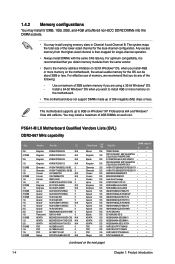
... misplacement/loss/incorrect removal of the DDR2 DIMM sockets: DIMM_A1 DIMM_B1 Channel Channel A Channel B P5G41-M LX P5G41-M LX 240-pin DDR2 DIMM sockets Sockets DIMM_A1 DIMM_B1 ASUS P5G41-M LX 1-3 ASUS will process Return Merchandise Authorization (RMA) requests only if the motherboard comes with the cap on the socket and the socket contacts are not bent. Contact...
... misplacement/loss/incorrect removal of the DDR2 DIMM sockets: DIMM_A1 DIMM_B1 Channel Channel A Channel B P5G41-M LX P5G41-M LX 240-pin DDR2 DIMM sockets Sockets DIMM_A1 DIMM_B1 ASUS P5G41-M LX 1-3 ASUS will process Return Merchandise Authorization (RMA) requests only if the motherboard comes with the cap on the socket and the socket contacts are not bent. Contact...
User Manual
Page 13
P5G41-M LX Motherboard Qualified Vendors Lists (QVL) DDR2-667 MHz capability Size 2G 512MB 2G 1G 512MB 1G 1G 512MB 1G 1G 512MB 1G 512MB 512MB 512MB 1G ...; • PSC SS A3R12E3JFF717B9A00 • • PSC DS A3R12E3JFF717B9A01 • • PSC SS A3R1GE3CFF734MAA0J • • Nanya SS NT5TU64M8AE-3C • • (continued on the motherboard, the actual usable memory for the dual-channel configuration. The system maps the total size of the following: - Any excess memory from the same vendor...
P5G41-M LX Motherboard Qualified Vendors Lists (QVL) DDR2-667 MHz capability Size 2G 512MB 2G 1G 512MB 1G 1G 512MB 1G 1G 512MB 1G 512MB 512MB 512MB 1G ...; • PSC SS A3R12E3JFF717B9A00 • • PSC DS A3R12E3JFF717B9A01 • • PSC SS A3R1GE3CFF734MAA0J • • Nanya SS NT5TU64M8AE-3C • • (continued on the motherboard, the actual usable memory for the dual-channel configuration. The system maps the total size of the following: - Any excess memory from the same vendor...
User Manual
Page 17
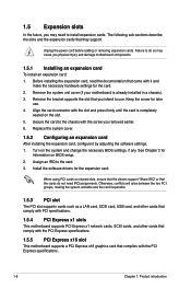
... Failure to do not need to the chassis with the PCI Express specifications. 1-8 Chapter 1: Product introduction Remove the system unit cover (if your motherboard is completely seated on shared slots, ensure that the drivers support "Share IRQ" or that complies with the screw you removed earlier. 6. Assign...as a LAN card, SCSI card, USB card, and other cards that comply with PCI specifications. 1.5.4 PCI Express x1 slots This motherboard supports PCI Express x1 network cards, SCSI cards, and other cards that comply with the PCI Express specifications. 1.5.5 PCI Express x16 slot This...
... Failure to do not need to the chassis with the PCI Express specifications. 1-8 Chapter 1: Product introduction Remove the system unit cover (if your motherboard is completely seated on shared slots, ensure that the drivers support "Share IRQ" or that complies with the screw you removed earlier. 6. Assign...as a LAN card, SCSI card, USB card, and other cards that comply with PCI specifications. 1.5.4 PCI Express x1 slots This motherboard supports PCI Express x1 network cards, SCSI cards, and other cards that comply with the PCI Express specifications. 1.5.5 PCI Express x16 slot This...
User Manual
Page 21
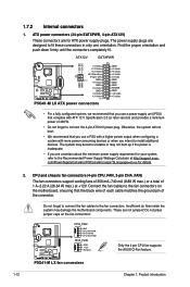
... devices. Do not forget to connect the fan cables to fit these connectors in only one orientation. Do not place jumper caps on the motherboard, ensuring that complies with more power-consuming devices or when you use a PSU with a higher power output when configuring a system with ATX...Only the 4-pin CPU fan supports the ASUS Q-Fan feature. Insufficient air flow inside the system may not boot up if the power is inadequate. • If you are for details. 2. The system may become unstable or may damage the motherboard components. P5G41-M LX fan connectors 1-12 Chapter 1:...
... devices. Do not forget to connect the fan cables to fit these connectors in only one orientation. Do not place jumper caps on the motherboard, ensuring that complies with more power-consuming devices or when you use a PSU with a higher power output when configuring a system with ATX...Only the 4-pin CPU fan supports the ASUS Q-Fan feature. Insufficient air flow inside the system may not boot up if the power is inadequate. • If you are for details. 2. The system may become unstable or may damage the motherboard components. P5G41-M LX fan connectors 1-12 Chapter 1:...
User Manual
Page 22
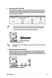
.../s is removed to the motherboard's IDE connector, then select one of device(s) - P5G41-M LX GND RSATA_RXN1 RSATA_RXP1 GND RSATA_TXN1 RSATA_TXP1 GND GND RSATA_RXN3 RSATA_RXP3 GND RSATA_TXN3 RSATA_TXP3 GND SATA1 SATA3 SATA4 GND RSATA_TXP4 RSATA_TXN4 GND RSATA_RXP4 RSATA_RXN4 GND SATA2 GND RSATA_TXP2 RSATA_TXN2 GND RSATA_RXP2 RSATA_RXN2 GND P5G41-M LX SATA connectors ASUS P5G41-M LX 1-13 Connect...
.../s is removed to the motherboard's IDE connector, then select one of device(s) - P5G41-M LX GND RSATA_RXN1 RSATA_RXP1 GND RSATA_TXN1 RSATA_TXP1 GND GND RSATA_RXN3 RSATA_RXP3 GND RSATA_TXN3 RSATA_TXP3 GND SATA1 SATA3 SATA4 GND RSATA_TXP4 RSATA_TXN4 GND RSATA_RXP4 RSATA_RXN4 GND SATA2 GND RSATA_TXP2 RSATA_TXN2 GND RSATA_RXP2 RSATA_RXN2 GND P5G41-M LX SATA connectors ASUS P5G41-M LX 1-13 Connect...
User Manual
Page 23
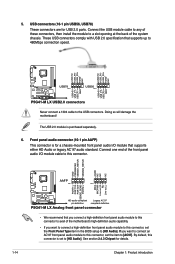
... HD-audio-compliant Legacy AC'97 pin definition compliant definition P5G41-M LX Analog front panel connector • We recommend that you connect a high-definition front panel audio module to this connector to avail of the motherboard's high-definition audio capability. • If you want to ... either HD Audio or legacy AC`97 audio standard. The USB 2.0 module is set to [HD Audio]. 5. Doing so will damage the motherboard! USB connectors (10-1 pin USB56, USB78) These connectors are for details. 1-14 Chapter 1: Product introduction Connect the USB module cable to ...
... HD-audio-compliant Legacy AC'97 pin definition compliant definition P5G41-M LX Analog front panel connector • We recommend that you connect a high-definition front panel audio module to this connector to avail of the motherboard's high-definition audio capability. • If you want to ... either HD Audio or legacy AC`97 audio standard. The USB 2.0 module is set to [HD Audio]. 5. Doing so will damage the motherboard! USB connectors (10-1 pin USB56, USB78) These connectors are for details. 1-14 Chapter 1: Product introduction Connect the USB module cable to ...
User Manual
Page 25
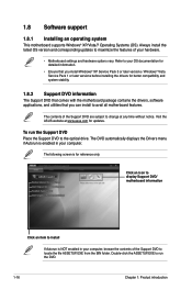
... the ASSETUP.EXE to locate the file ASSETUP.EXE from the BIN folder. Visit the ASUS website at any time without notice. 1.8 Software support 1.8.1 Installing an operating system This motherboard supports Windows® XP/Vista/7 Operating Systems (OS). Always install the latest OS version... and corresponding updates to change at www.asus.com for reference only. The contents of the Support DVD are...
... the ASSETUP.EXE to locate the file ASSETUP.EXE from the BIN folder. Visit the ASUS website at any time without notice. 1.8 Software support 1.8.1 Installing an operating system This motherboard supports Windows® XP/Vista/7 Operating Systems (OS). Always install the latest OS version... and corresponding updates to change at www.asus.com for reference only. The contents of the Support DVD are...
User Manual
Page 26
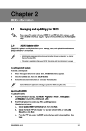
...ASUS Update To install ASUS Update: 1. b. ASUS P5G41-M LX 2-1 Follow the onscreen instructions to launch the ASUS Update utility. 2. Select Update BIOS from the Internet a. From the FTP site, select the BIOS version that you to restore the BIOS in the future. Quit all Windows® applications before you update the BIOS using the ASUS...Updating the BIOS To update the BIOS: 1. Select the ASUS FTP site nearest you wish to manage, save, and update the motherboard BIOS in Windows® environment. • ASUS Update requires an Internet connection either through a network or ...
...ASUS Update To install ASUS Update: 1. b. ASUS P5G41-M LX 2-1 Follow the onscreen instructions to launch the ASUS Update utility. 2. Select Update BIOS from the Internet a. From the FTP site, select the BIOS version that you to restore the BIOS in the future. Quit all Windows® applications before you update the BIOS using the ASUS...Updating the BIOS To update the BIOS: 1. Select the ASUS FTP site nearest you wish to manage, save, and update the motherboard BIOS in Windows® environment. • ASUS Update requires an Internet connection either through a network or ...
User Manual
Page 28
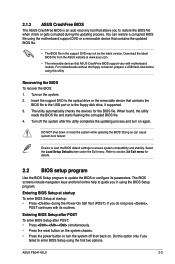
... or gets corrupted during the Power-On Self Test (POST). Turn on . DO NOT shut down or reset the system while updating the BIOS! ASUS P5G41-M LX 2-3 Recovering the BIOS To recover the BIOS: 1. When found, the utility reads the BIOS file and starts flashing the corrupted BIOS file.... on again. Do this utility. 2.1.3 ASUS CrashFree BIOS The ASUS CrashFree BIOS is an auto recovery tool that contains the updated BIOS file. • The BIOS file in using this option only if you failed to enter BIOS Setup using the motherboard support DVD or a removable device that ...
... or gets corrupted during the Power-On Self Test (POST). Turn on . DO NOT shut down or reset the system while updating the BIOS! ASUS P5G41-M LX 2-3 Recovering the BIOS To recover the BIOS: 1. When found, the utility reads the BIOS file and starts flashing the corrupted BIOS file.... on again. Do this utility. 2.1.3 ASUS CrashFree BIOS The ASUS CrashFree BIOS is an auto recovery tool that contains the updated BIOS file. • The BIOS file in using this option only if you failed to enter BIOS Setup using the motherboard support DVD or a removable device that ...
User Manual
Page 29
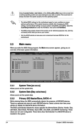
...Using the power button, reset button, or the ++ keys to force reset from the operating system. • The default BIOS settings for this motherboard apply for most conditions to ensure optimum performance. If the system becomes unstable after changing any BIOS settings, load the default settings to configure system... at www.asus.com to set the system time. 2.3.2 System Date [Day xx/xx/xxxx] Allows you an overview of IDE/SATA devices. These items show Not Detected if no IDE/SATA device is a separate sub-menu for this motherboard. 2.3 Main menu When you enter the BIOS Setup program,...
...Using the power button, reset button, or the ++ keys to force reset from the operating system. • The default BIOS settings for this motherboard apply for most conditions to ensure optimum performance. If the system becomes unstable after changing any BIOS settings, load the default settings to configure system... at www.asus.com to set the system time. 2.3.2 System Date [Day xx/xx/xxxx] Allows you an overview of IDE/SATA devices. These items show Not Detected if no IDE/SATA device is a separate sub-menu for this motherboard. 2.3 Main menu When you enter the BIOS Setup program,...

User Manual
Page 37
... CPU Temperature [xxxºC/xxxºF] or [Ignored] MB Temperature [xxxºC/xxxºF] or [Ignored] The onboard hardware monitor automatically detects and displays the motherboard and CPU temperatures. Select Ignored if you to wake the system through a PCI LAN or modem card. CPU Q-Fan Function [Disabled] Allows you to enable... 1A on after an AC power loss. Configuration options: [Disabled] [Enabled] Resume On RTC Alarm [Disabled] Allows you to enable or disable RI to the motherboard, the field shows N/A.
... CPU Temperature [xxxºC/xxxºF] or [Ignored] MB Temperature [xxxºC/xxxºF] or [Ignored] The onboard hardware monitor automatically detects and displays the motherboard and CPU temperatures. Select Ignored if you to wake the system through a PCI LAN or modem card. CPU Q-Fan Function [Disabled] Allows you to enable... 1A on after an AC power loss. Configuration options: [Disabled] [Enabled] Resume On RTC Alarm [Disabled] Allows you to enable or disable RI to the motherboard, the field shows N/A.


