User Manual
Page 16
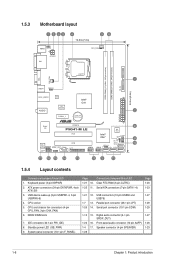
... connectors (4-pin CPU_FAN, 3-pin CHA_FAN) 6. Parallel port connector (26-1 pin LPT) 1-26 14. CPU socket 5. Connectors/Jumpers/Slots/LED Clear RTC RAM (3-pin CLTRC) Serial ATA connectors (7-pin SATA 1-4) 1-21 12. USB device wake-up (3-pin USBPW1-4, 3-pin USBPW5-8) 4. Speaker connector (4-pin SPEAKER....4cm(9.6in) LAN1_USB12 Atheros L1E Intel® G41 ICS 9LRS954 AUDIO 2 PCIEX1_1 Lithium Cell CMOS Power EATXPWR Super I/O PCIEX16 P5G41-M LE PCI1 RTL Audio codec SPEAKER SPDIF_OUT COM1 AAFP PCI2 LPT USB56 Intel® ICH7 8Mb BIOS F_PANEL CLRTC USB78 SB_PWR USBPW5-8 ...
... connectors (4-pin CPU_FAN, 3-pin CHA_FAN) 6. Parallel port connector (26-1 pin LPT) 1-26 14. CPU socket 5. Connectors/Jumpers/Slots/LED Clear RTC RAM (3-pin CLTRC) Serial ATA connectors (7-pin SATA 1-4) 1-21 12. USB device wake-up (3-pin USBPW1-4, 3-pin USBPW5-8) 4. Speaker connector (4-pin SPEAKER....4cm(9.6in) LAN1_USB12 Atheros L1E Intel® G41 ICS 9LRS954 AUDIO 2 PCIEX1_1 Lithium Cell CMOS Power EATXPWR Super I/O PCIEX16 P5G41-M LE PCI1 RTL Audio codec SPEAKER SPDIF_OUT COM1 AAFP PCI2 LPT USB56 Intel® ICH7 8Mb BIOS F_PANEL CLRTC USB78 SB_PWR USBPW5-8 ...

User Manual
Page 32
... down and reboot the system, then the BIOS automatically resets parameter settings to default values. • Due to clear the CMOS RTC RAM data. Move the jumper cap from pins 1-2 (default) to re-enter data. Plug the power cord and turn off is required ...the cap back to overclocking, use the C.P.R. You must turn ON the computer. 4. CLRTC 12 23 P5G41-M LE Normal (Default) P5G41-M LE Clear RTC RAM Clear RTC To erase the RTC RAM: 1. 1.9 Jumpers 1. Clear RTC RAM (3-pin CLRTC) This jumper allows you use the CPU Parameter Recall (C.P.R.) feature. For system failure due ...
... down and reboot the system, then the BIOS automatically resets parameter settings to default values. • Due to clear the CMOS RTC RAM data. Move the jumper cap from pins 1-2 (default) to re-enter data. Plug the power cord and turn off is required ...the cap back to overclocking, use the C.P.R. You must turn ON the computer. 4. CLRTC 12 23 P5G41-M LE Normal (Default) P5G41-M LE Clear RTC RAM Clear RTC To erase the RTC RAM: 1. 1.9 Jumpers 1. Clear RTC RAM (3-pin CLRTC) This jumper allows you use the CPU Parameter Recall (C.P.R.) feature. For system failure due ...

User Manual
Page 46
... system provides you scroll through the various submenus and make it lets you with the opportunity to use the Setup program, you can support ASUS CrashFree BIOS 3. The SPI chip on the system chassis. • Press the power button to "Run Setup." We recommend to enter ...can enable the security password feature or change the configuration of your data or system. This section explains how to your computer in the CMOS RAM of the following procedures: • Restart using the OS standard shutdown procedure. • Press ++ simultaneously. • Press the reset button...
... system provides you scroll through the various submenus and make it lets you with the opportunity to use the Setup program, you can support ASUS CrashFree BIOS 3. The SPI chip on the system chassis. • Press the power button to "Run Setup." We recommend to enter ...can enable the security password feature or change the configuration of your data or system. This section explains how to your computer in the CMOS RAM of the following procedures: • Restart using the OS standard shutdown procedure. • Press ++ simultaneously. • Press the reset button...

User Manual
Page 57
... to enable or disable the Advanced Configuration and Power Interface (ACPI) support in the RSDT pointer list. Configuration options: [Power Off] [Power On] [Last State] ASUS P5G41-M LE 2-15 Enables the system to enter the ACPI S3 (Suspend to enable or disable the over-voltage protection function. Main Advanced Power BIOS SETUP UTILITY... Configuration Hardware Monitor Select the ACPI state used for system suspend. The system can be used for System Suspend. 2.5.1 Suspend Mode [Auto] Allows you to RAM) sleep state (default).
... to enable or disable the Advanced Configuration and Power Interface (ACPI) support in the RSDT pointer list. Configuration options: [Power Off] [Power On] [Last State] ASUS P5G41-M LE 2-15 Enables the system to enter the ACPI S3 (Suspend to enable or disable the over-voltage protection function. Main Advanced Power BIOS SETUP UTILITY... Configuration Hardware Monitor Select the ACPI state used for system suspend. The system can be used for System Suspend. 2.5.1 Suspend Mode [Auto] Allows you to RAM) sleep state (default).
User Manual
Page 60
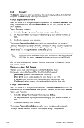
... after you to set a Supervisor Password: 1. The Supervisor Password item on how to any field. [Limited] - To change to erase the RTC RAM. To clear the supervisor password, select the Change Supervisor Password then press twice. After you have set a supervisor password, the other security settings. User... Access Level [Full Access] This item allows you can clear it by erasing the CMOS Real Time Clock (RTC) RAM. To set or change the system security settings. If you forget your BIOS password, you to select the access restriction to allow you set...
... after you to set a Supervisor Password: 1. The Supervisor Password item on how to any field. [Limited] - To change to erase the RTC RAM. To clear the supervisor password, select the Change Supervisor Password then press twice. After you have set a supervisor password, the other security settings. User... Access Level [Full Access] This item allows you can clear it by erasing the CMOS Real Time Clock (RTC) RAM. To set or change the system security settings. If you forget your BIOS password, you to select the access restriction to allow you set...
User Manual
Page 62
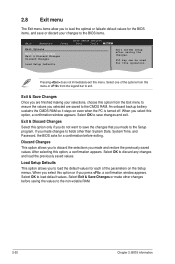
...turned off. Select+FFEEFFEo-11Sn11Sn0Ct0CeeorSSCGSEf eeheaxtSSGGSEhllanvieeoeaxeeeneetllnviccgroeeteettteaapccorlntttaaioSIOdSlnnctpHSIudsreteEctbHemilxfre-eEreopioemslxnntmecpinrtteheisn Exit & Save Changes Once you are saved to the CMOS RAM. When you press , a confirmation window appears. Select OK to discard any changes and load the ... Select OK to save changes and exit. F1F010kekyeycacnanbebeusuesded fofrorthtihsisopoepreartaitoino.n. An onboard backup battery sustains the CMOS RAM so it stays on the Setup menus. After selecting this option only if you made and restore...
...turned off. Select+FFEEFFEo-11Sn11Sn0Ct0CeeorSSCGSEf eeheaxtSSGGSEhllanvieeoeaxeeeneetllnviccgroeeteettteaapccorlntttaaioSIOdSlnnctpHSIudsreteEctbHemilxfre-eEreopioemslxnntmecpinrtteheisn Exit & Save Changes Once you are saved to the CMOS RAM. When you press , a confirmation window appears. Select OK to discard any changes and load the ... Select OK to save changes and exit. F1F010kekyeycacnanbebeusuesded fofrorthtihsisopoepreartaitoino.n. An onboard backup battery sustains the CMOS RAM so it stays on the Setup menus. After selecting this option only if you made and restore...


