User Manual
Page 4
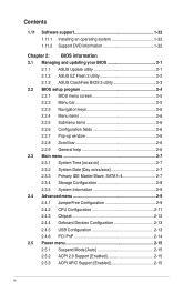
... Pop-up window 2-6 2.2.8 Scroll bar 2-6 2.2.9 General help 2-6 2.3 Main menu 2-7 2.3.1 System Time [xx:xx:xx 2-7 2.3.2 System Date [Day xx/xx/xxxx 2-7 2.3.3 Primary IDE Master/Slave, SATA1~4 2-7 2.3.4 Storage Configuration 2-8 2.3.5 System Information 2-9 2.4 Advanced menu 2-9 2.4.1 JumperFree Configuration 2-9 2.4.2 CPU Configuration 2-11 2.4.3 Chipset 2-12 2.4.4 Onboard Devices Configuration 2-13 2.4.5 USB Configuration 2-13 2.4.6 PCI PnP 2-14 2.5 Power menu 2-15 2.5.1 Suspend Mode [Auto 2-15 2.5.2 ACPI 2.0 Support [Enabled 2-15 2.5.3 ACPI APIC Support [Enabled 2-15 iv
... Pop-up window 2-6 2.2.8 Scroll bar 2-6 2.2.9 General help 2-6 2.3 Main menu 2-7 2.3.1 System Time [xx:xx:xx 2-7 2.3.2 System Date [Day xx/xx/xxxx 2-7 2.3.3 Primary IDE Master/Slave, SATA1~4 2-7 2.3.4 Storage Configuration 2-8 2.3.5 System Information 2-9 2.4 Advanced menu 2-9 2.4.1 JumperFree Configuration 2-9 2.4.2 CPU Configuration 2-11 2.4.3 Chipset 2-12 2.4.4 Onboard Devices Configuration 2-13 2.4.5 USB Configuration 2-13 2.4.6 PCI PnP 2-14 2.5 Power menu 2-15 2.5.1 Suspend Mode [Auto 2-15 2.5.2 ACPI 2.0 Support [Enabled 2-15 2.5.3 ACPI APIC Support [Enabled 2-15 iv
User Manual
Page 12
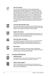
... Side Bus (FSB), PCIe 1.1, and multi-core CPUs. ASUS CrashFree BIOS 3 ASUS CrashFree BIOS 3 is enhanced with the next-generation Intel® Graphics Media Acceleratior X4500. 1.3.2 Intel® G41 Chipset The Intel® G41 Express Chipset is a highly integrated Gb LAN controller. Shader Model 4.0 and OpenGL 2.1. Gigabit LAN solution The onboard LAN controller is the latest chipset designed to provide efficient power management for advanced operating systems. Serial ATA 3Gb/s technology This motherboard supports hard drives based...
... Side Bus (FSB), PCIe 1.1, and multi-core CPUs. ASUS CrashFree BIOS 3 ASUS CrashFree BIOS 3 is enhanced with the next-generation Intel® Graphics Media Acceleratior X4500. 1.3.2 Intel® G41 Chipset The Intel® G41 Express Chipset is a highly integrated Gb LAN controller. Shader Model 4.0 and OpenGL 2.1. Gigabit LAN solution The onboard LAN controller is the latest chipset designed to provide efficient power management for advanced operating systems. Serial ATA 3Gb/s technology This motherboard supports hard drives based...
User Manual
Page 16
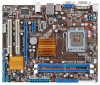
...System panel connector (10-1 pin F_PANEL) Page 1-21 10. 1-25 11. Connectors/Jumpers/Slots/LED Clear RTC RAM (3-pin CLTRC) Serial ATA connectors (7-pin SATA 1-4) 1-21 12. Standby power LED (SB_PWR) 9. Parallel port connector (26-1 pin LPT) 1-26 14. ATX power connectors (24-pin EATXPWR, 4-pin ATX12V) 3. USB connectors (10-pin USB56 and USB78) 1-7 13. Front panel audio connector (10-pin AAFP) 1-4 17. CPU and chassis fan connectors (4-pin CPU_FAN, 3-pin CHA_FAN) 6. IDE connector (40-1 pin PRI_IDE) 8. USB device wake-up (3-pin USBPW1-4, 3-pin USBPW5-8) 4. 1.5.3 Motherboard layout...
...System panel connector (10-1 pin F_PANEL) Page 1-21 10. 1-25 11. Connectors/Jumpers/Slots/LED Clear RTC RAM (3-pin CLTRC) Serial ATA connectors (7-pin SATA 1-4) 1-21 12. Standby power LED (SB_PWR) 9. Parallel port connector (26-1 pin LPT) 1-26 14. ATX power connectors (24-pin EATXPWR, 4-pin ATX12V) 3. USB connectors (10-pin USB56 and USB78) 1-7 13. Front panel audio connector (10-pin AAFP) 1-4 17. CPU and chassis fan connectors (4-pin CPU_FAN, 3-pin CHA_FAN) 6. IDE connector (40-1 pin PRI_IDE) 8. USB device wake-up (3-pin USBPW1-4, 3-pin USBPW5-8) 4. 1.5.3 Motherboard layout...
User Manual
Page 23
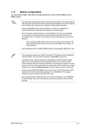
... sockets. • You may install a maximum of the lower-sized channel for the dual-channel configuration. If this happens, contact your memory vendor to check the ODT value. • Due to chipset limitation, DDR2-800 with CL=4 will automatically downgrade to the memory address limitation on 32-bit Windows® OS, when you install 4GB or more memory on the motherboard. • This motherboard does not support...
... sockets. • You may install a maximum of the lower-sized channel for the dual-channel configuration. If this happens, contact your memory vendor to check the ODT value. • Due to chipset limitation, DDR2-800 with CL=4 will automatically downgrade to the memory address limitation on 32-bit Windows® OS, when you install 4GB or more memory on the motherboard. • This motherboard does not support...
User Manual
Page 31
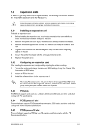
... assignments. Keep the screw for the card. 2. ASUS P5G41-M LE 1-21 Install the software drivers for information on shared slots, ensure that the drivers support "Share IRQ" or that came with the slot and press firmly until the card is already installed in a chassis). 3. Unplug the power cord before adding or removing expansion cards. When using PCI cards on BIOS setup. 2. Secure the card to install expansion cards. Turn on the slot. 5. See Chapter 2 for the expansion...
... assignments. Keep the screw for the card. 2. ASUS P5G41-M LE 1-21 Install the software drivers for information on shared slots, ensure that the drivers support "Share IRQ" or that came with the slot and press firmly until the card is already installed in a chassis). 3. Unplug the power cord before adding or removing expansion cards. When using PCI cards on BIOS setup. 2. Secure the card to install expansion cards. Turn on the slot. 5. See Chapter 2 for the expansion...
User Manual
Page 33
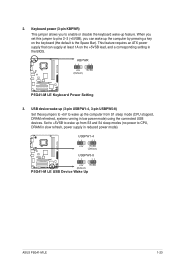
... +5V +5VSB (Default) P5G41-M LE P5G41-M LE Keyboard Power Setting 3. USBPW1-4 12 23 +5V +5VSB (Default) USBPW5-8 P5G41-M LE 12 23 +5V +5VSB (Default) P5G41-M LE USB Device Wake Up ASUS P5G41-M LE 1-23 This feature requires an ATX power supply that can wake up feature. Keyboard power (3-pin KBPWR) This jumper allows you can supply at least 1A on the keyboard (the default is the Space Bar). When you set this jumper to pins 2-3 (+5VSB), you to CPU, DRAM in slow refresh, power supply in low power mode) using the connected USB devices. 2.
... +5V +5VSB (Default) P5G41-M LE P5G41-M LE Keyboard Power Setting 3. USBPW1-4 12 23 +5V +5VSB (Default) USBPW5-8 P5G41-M LE 12 23 +5V +5VSB (Default) P5G41-M LE USB Device Wake Up ASUS P5G41-M LE 1-23 This feature requires an ATX power supply that can wake up feature. Keyboard power (3-pin KBPWR) This jumper allows you can supply at least 1A on the keyboard (the default is the Space Bar). When you set this jumper to pins 2-3 (+5VSB), you to CPU, DRAM in slow refresh, power supply in low power mode) using the connected USB devices. 2.
User Manual
Page 42
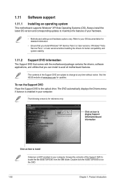
... following screen is NOT enabled in your OS documentation for detailed information. • Ensure that you install Windows® XP Service Pack 3 or later versions / Windows® Vista Service Pack 1 or later versions before installing the drivers for better compatibility and system stability. 1.11.2 Support DVD information The Support DVD that comes with the motherboard package contains the drivers, software applications, and utilities that you can install to change at www.asus.com...
... following screen is NOT enabled in your OS documentation for detailed information. • Ensure that you install Windows® XP Service Pack 3 or later versions / Windows® Vista Service Pack 1 or later versions before installing the drivers for better compatibility and system stability. 1.11.2 Support DVD information The Support DVD that comes with the motherboard package contains the drivers, software applications, and utilities that you can install to change at www.asus.com...
User Manual
Page 43
The Drivers menu appears. 2. Installing ASUS Update To install ASUS Update: 1. Follow the onscreen instructions to launch the ASUS Update utility. 2. Place the support DVD in the future. From the dropdown list, select any of the original motherboard BIOS file to a USB flash disk in case you to manage, save, and update the motherboard BIOS in Windows® environment. • ASUS Update requires an Internet connection either through a network or an Internet Service Provider (ISP). • This utility is available in the support DVD that...
The Drivers menu appears. 2. Installing ASUS Update To install ASUS Update: 1. Follow the onscreen instructions to launch the ASUS Update utility. 2. Place the support DVD in the future. From the dropdown list, select any of the original motherboard BIOS file to a USB flash disk in case you to manage, save, and update the motherboard BIOS in Windows® environment. • ASUS Update requires an Internet connection either through a network or an Internet Service Provider (ISP). • This utility is available in the support DVD that...
User Manual
Page 45
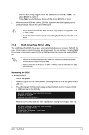
Starting BIOS recovery... Start Erasing...\ ASUS P5G41-M LE 2-3 Press to switch between drives until the correct BIOS file is an auto recovery tool that contains the updated BIOS file. • Prepare the motherboard support DVD or the USB flash disk containing the updated motherboard BIOS before using the motherboard support DVD or a USB flash disk that allows you to restore the BIOS file when it . Otherwise, the utility will not function. Recovering the BIOS To recover the BIOS: 1. Checking for USB Device... Reading file "P5G41MLE". Completed. Go to the Tools menu ...
Starting BIOS recovery... Start Erasing...\ ASUS P5G41-M LE 2-3 Press to switch between drives until the correct BIOS file is an auto recovery tool that contains the updated BIOS file. • Prepare the motherboard support DVD or the USB flash disk containing the updated motherboard BIOS before using the motherboard support DVD or a USB flash disk that allows you to restore the BIOS file when it . Otherwise, the utility will not function. Recovering the BIOS To recover the BIOS: 1. Checking for USB Device... Reading file "P5G41MLE". Completed. Go to the Tools menu ...

User Manual
Page 47
... the ASUS website at www.asus.com to download the latest BIOS file for this motherboard. 2.2.1 BIOS menu screen Menu items Menu bar Main Advanced Power Configuration fields BIOS SETUP UTILITY Boot Tools Exit General help System Time [00:31:48] System Date [Mon 01/14/2002] Use [ENTER], [TAB] or [SHIFT-TAB] to ensure optimum performance. For changing the advanced system settings. For changing the system boot configuration. For selecting the exit options and loading default settings. Change Field...
... the ASUS website at www.asus.com to download the latest BIOS file for this motherboard. 2.2.1 BIOS menu screen Menu items Menu bar Main Advanced Power Configuration fields BIOS SETUP UTILITY Boot Tools Exit General help System Time [00:31:48] System Date [Mon 01/14/2002] Use [ENTER], [TAB] or [SHIFT-TAB] to ensure optimum performance. For changing the advanced system settings. For changing the system boot configuration. For selecting the exit options and loading default settings. Change Field...
User Manual
Page 48
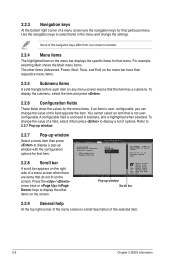
... description of options. For example, selecting Main shows the Main menu items. The other items on the screen. Main Advanced BIOS SETUP UTILITY Power Boot Tools Exit Suspend Mode ACPI Version Features ACPI APIC support APM Configuration Hardware Monitor [Auto] [Disabled] [EDniOsapabtbilloendesd] Enabled Use [ENTER], [TAB] or [SHIFT-TAB] to display a list of the selected item. 2-6 Chapter 2: BIOS information 2.2.3 Navigation keys At the bottom right corner of the navigation keys differ from one screen to another. 2.2.4 Menu items The highlighted...
... description of options. For example, selecting Main shows the Main menu items. The other items on the screen. Main Advanced BIOS SETUP UTILITY Power Boot Tools Exit Suspend Mode ACPI Version Features ACPI APIC support APM Configuration Hardware Monitor [Auto] [Disabled] [EDniOsapabtbilloendesd] Enabled Use [ENTER], [TAB] or [SHIFT-TAB] to display a list of the selected item. 2-6 Chapter 2: BIOS information 2.2.3 Navigation keys At the bottom right corner of the navigation keys differ from one screen to another. 2.2.4 Menu items The highlighted...
User Manual
Page 49
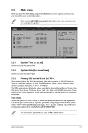
... Mode, PIO Mode, Async DMA, Ultra DMA, and SMART monitoring). These values are specifically configuring a CD-ROM drive. 2.3 Main menu When you enter the BIOS Setup program, the Main menu screen appears, giving you select the SATA 1/2/3/4 devices. Use [+] or [-] to select a field. There is a separate submenu for information on the menu screen items and how to section 2.2.1 BIOS menu screen for each IDE/SATA device. Select ARMD (ATAPI Removable Media Device) if your device is installed in the system. Configuration options: [Not Installed] [Auto...
... Mode, PIO Mode, Async DMA, Ultra DMA, and SMART monitoring). These values are specifically configuring a CD-ROM drive. 2.3 Main menu When you enter the BIOS Setup program, the Main menu screen appears, giving you select the SATA 1/2/3/4 devices. Use [+] or [-] to select a field. There is a separate submenu for information on the menu screen items and how to section 2.2.1 BIOS menu screen for each IDE/SATA device. Select ARMD (ATAPI Removable Media Device) if your device is installed in the system. Configuration options: [Not Installed] [Auto...
User Manual
Page 50
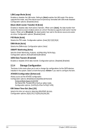
.../IDE configuration. Configuration options: [Disabled] [Enabled] 2.3.4 Storage Configuration The items in the system. Configuration option: [Auto] SMART Monitoring [Auto] Sets the Smart Monitoring, Analysis, and Reporting Technology. Setting to [Auto] enables the LBA mode if the device supports this menu allow you want to the device occurs multiple sectors at a time. ATA/IDE Configuration [Enhanced] Allows you to set to [Disabled], the data transfer from and to configure the item. Configuration options: [Disabled] [Compatible] [Enhanced] Enhanced Mode Support On [S-ATA] Set Serial...
.../IDE configuration. Configuration options: [Disabled] [Enabled] 2.3.4 Storage Configuration The items in the system. Configuration option: [Auto] SMART Monitoring [Auto] Sets the Smart Monitoring, Analysis, and Reporting Technology. Setting to [Auto] enables the LBA mode if the device supports this menu allow you want to the device occurs multiple sectors at a time. ATA/IDE Configuration [Enhanced] Allows you to set to [Disabled], the data transfer from and to configure the item. Configuration options: [Disabled] [Compatible] [Enhanced] Enhanced Mode Support On [S-ATA] Set Serial...
User Manual
Page 51
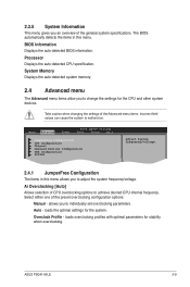
... when changing the settings of CPU overclocking options to malfunction. Main Advanced Power BIOS SETUP UTILITY Boot Tools Exit JumperFree Configuration CPU Configuration Chipset Onboard Devices Configuration USB Configuration PCIPnP Adjust System frequency/voltage. 2.4.1 JumperFree Configuration The items in this menu allows you to individually set overclocking parameters. Auto - Overclock Profile - Ai Overclocking [Auto] Allows selection of the Advanced menu items. Incorrect field values can cause the system to achieve desired CPU internal frequency. ASUS P5G41-M LE...
... when changing the settings of CPU overclocking options to malfunction. Main Advanced Power BIOS SETUP UTILITY Boot Tools Exit JumperFree Configuration CPU Configuration Chipset Onboard Devices Configuration USB Configuration PCIPnP Adjust System frequency/voltage. 2.4.1 JumperFree Configuration The items in this menu allows you to individually set overclocking parameters. Auto - Overclock Profile - Ai Overclocking [Auto] Allows selection of the Advanced menu items. Incorrect field values can cause the system to achieve desired CPU internal frequency. ASUS P5G41-M LE...
User Manual
Page 54
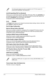
... change the advanced chipset settings. When set to enabled or disable the remapping of system memory used by SPD. Select an item then press to use the EIST. Configuration options: [Disabled] [Enabled, 32MB] [Enabled, 64MB] [Enabled, 128MB] GTT Graphics Memory Size [No VT mode, 2MB] This item is not user- Configuration options: [Enabled] [Disabled] Initiate Graphic Adapter [PEG/PCI] Allows you to [Enabled], you install 64-bit operating system. North Bridge Configuration Memory Remap Feature [Enabled] Allows you to decide which graphics controller to display...
... change the advanced chipset settings. When set to enabled or disable the remapping of system memory used by SPD. Select an item then press to use the EIST. Configuration options: [Disabled] [Enabled, 32MB] [Enabled, 64MB] [Enabled, 128MB] GTT Graphics Memory Size [No VT mode, 2MB] This item is not user- Configuration options: [Enabled] [Disabled] Initiate Graphic Adapter [PEG/PCI] Allows you to [Enabled], you install 64-bit operating system. North Bridge Configuration Memory Remap Feature [Enabled] Allows you to decide which graphics controller to display...

User Manual
Page 55
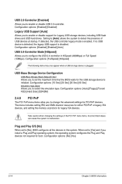
...] [Disabled] LAN Option ROM [Disabled] Allows you to select the Parallel Port EPP version. Configuration options: [Disabled] [Enabled] Serial Port1 Address [3F8/IRQ4] Allows you to enable or disable the boot ROM in this item to select the front panel support type. This item allows you to select the Parallel Port base addresses. Configuration options: [IRQ5] [IRQ7] 2.4.5 USB Configuration The items in the onboard LAN controller. Configuration options: [Disabled] [Enabled] ASUS P5G41-M LE 2-13 Configuration options: [AC97] [HD Audio] 2.4.4 Onboard Devices Configuration Onboard LAN...
...] [Disabled] LAN Option ROM [Disabled] Allows you to select the Parallel Port EPP version. Configuration options: [Disabled] [Enabled] Serial Port1 Address [3F8/IRQ4] Allows you to enable or disable the boot ROM in this item to select the front panel support type. This item allows you to select the Parallel Port base addresses. Configuration options: [IRQ5] [IRQ7] 2.4.5 USB Configuration The items in the onboard LAN controller. Configuration options: [Disabled] [Enabled] ASUS P5G41-M LE 2-13 Configuration options: [AC97] [HD Audio] 2.4.4 Onboard Devices Configuration Onboard LAN...
User Manual
Page 56
... a USB storage device is plugged. Configuration options: [10 Sec] [20 Sec] [30 Sec] [40 Sec] Emulation Type [Auto] Allows you to configure the USB 2.0 controller in the system. Configuration options: [Auto] [Floppy] [Forced FDD] [Hard Disk] [CDROM] 2.4.6 PCI PnP The PCI PnP menu items allow you to change the advanced settings for legacy ISA devices. The menu includes setting IRQ and DMA channel resources for either PCI/PnP or legacy ISA devices, and setting the memory size block for PCI/PnP devices. USB Mass Storage Device Configuration USB Mass Storage Reset Delay...
... a USB storage device is plugged. Configuration options: [10 Sec] [20 Sec] [30 Sec] [40 Sec] Emulation Type [Auto] Allows you to configure the USB 2.0 controller in the system. Configuration options: [Auto] [Floppy] [Forced FDD] [Hard Disk] [CDROM] 2.4.6 PCI PnP The PCI PnP menu items allow you to change the advanced settings for legacy ISA devices. The menu includes setting IRQ and DMA channel resources for either PCI/PnP or legacy ISA devices, and setting the memory size block for PCI/PnP devices. USB Mass Storage Device Configuration USB Mass Storage Reset Delay...

User Manual
Page 57
Main Advanced Power BIOS SETUP UTILITY Boot Tools Exit Suspend Mode ACPI 2.0 Support ACPI APIC Support Anti Surgy Support [Auto] [Disabled] [Enabled] [Enabled] APM Configuration Hardware Monitor Select the ACPI state used for System Suspend. 2.5.1 Suspend Mode [Auto] Allows you to select the Advanced Configuration and Power Interface (ACPI) state to be used for the Advanced Power Management (APM). When set to Enabled, the ACPI APIC table pointer is included in a low power mode. Configuration options: [Disabled] [Enabled] 2.5.5 APM Configuration Restore on state, whatever ...
Main Advanced Power BIOS SETUP UTILITY Boot Tools Exit Suspend Mode ACPI 2.0 Support ACPI APIC Support Anti Surgy Support [Auto] [Disabled] [Enabled] [Enabled] APM Configuration Hardware Monitor Select the ACPI state used for System Suspend. 2.5.1 Suspend Mode [Auto] Allows you to select the Advanced Configuration and Power Interface (ACPI) state to be used for the Advanced Power Management (APM). When set to Enabled, the ACPI APIC table pointer is included in a low power mode. Configuration options: [Disabled] [Enabled] 2.5.5 APM Configuration Restore on state, whatever ...
User Manual
Page 59
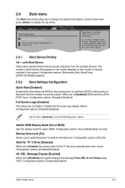
... to boot the system. Configuration options: [Removable Dev.] [Hard Drive] [ATAPI CD-ROM] [Disabled] 2.6.2 Boot Settings Configuration Quick Boot [Enabled] Enabling this item to [Enabled] to run Setup during POST. When set to [Enabled], the system displays the message Press DEL to use the ASUS MyLogo2™ feature. AddOn ROM Display Mode [Force BIOS] Sets the display mode for the NumLock. A virtual floppy disk drive (Floppy Drive B: ) may appear when you set to Enabled, the system waits for the F1 key to change the system boot options. The number of devices installed in...
... to boot the system. Configuration options: [Removable Dev.] [Hard Drive] [ATAPI CD-ROM] [Disabled] 2.6.2 Boot Settings Configuration Quick Boot [Enabled] Enabling this item to [Enabled] to run Setup during POST. When set to [Enabled], the system displays the message Press DEL to use the ASUS MyLogo2™ feature. AddOn ROM Display Mode [Force BIOS] Sets the display mode for the NumLock. A virtual floppy disk drive (Floppy Drive B: ) may appear when you set to Enabled, the system waits for the F1 key to change the system boot options. The number of devices installed in...
User Manual
Page 61
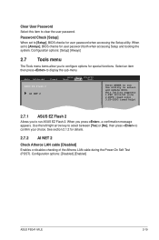
...], BIOS checks for user password when accessing the Setup utility. When you to confirm your choice. When set to run the utility to clear the user password. Use the left/right arrow key to select between [Yes] or [No], then press to configure options for details. 2.7.2 AI NET 2 Check Atheros LAN cable [Disabled] Enables or disables checking of the Atheros LAN cable during the Power-On Self‑Test (POST). Configuration options: [Disabled] [Enabled] ASUS P5G41-M LE 2-19 Configuration options: [Setup] [Always] 2.7 Tools menu The...
...], BIOS checks for user password when accessing the Setup utility. When you to confirm your choice. When set to run the utility to clear the user password. Use the left/right arrow key to select between [Yes] or [No], then press to configure options for details. 2.7.2 AI NET 2 Check Atheros LAN cable [Disabled] Enables or disables checking of the Atheros LAN cable during the Power-On Self‑Test (POST). Configuration options: [Disabled] [Enabled] ASUS P5G41-M LE 2-19 Configuration options: [Setup] [Always] 2.7 Tools menu The...


